Ridder Aqua CX300 User manual

SV -
02/03/2020
96010102
User Manual
Aqua CX300

Ridder Growing Solutions B.V. Mailing address
Honderdland 131 Postbus 33
2676 LT Maasdijk 2676 ZG Maasdijk
The Netherlands The Netherlands
Tel : +31(0)15 3620300 Website: www.ridder.com
E-mail: info@gs.ridder.com, sales@gs.ridder.com,
helpdesk@gs.ridder.com
All efforts have been made to ensure the accuracy of the contents of this manual.
Should any errors be discovered, however, Ridder Growing Solutions B.V. would
greatly appreciate being informed of them. Ridder Growing Solutions B.V. is
naturally very interested in your comments and additions.
This product is subject to the General Conditions of Ridder Growing Solutions
B.V.
This document may not be copied or made public by means of printing,
photocopying, digital copying or any other process, without the prior written
permission of Ridder Growing Solutions B.V.
Publication date: 02/03/2020 09:10 Manual version number: 040 Item code:
96010102

Contents
1 Introduction 5
1.1 Available Aqua CX300 models 5
1.1.1 Certificates and declarations 6
1.1.2 Type plates 6
1.2 How the Aqua CX300 works 7
1.3 Valve groups and valves 7
1.4 Irrigation programs 7
1.5 Start options 8
1.6 EC and pH control 8
1.7 Irrigation 8
1.8 General 9
1.9 Type of irrigation 9
2 Operation 10
2.1 Switching on the controller 10
2.2 Keyboard 10
2.3 Displaying data and entering settings 12
2.3.1 Displaying data 12
2.3.2 Entering settings 12
2.3.3 Alarms 13
3 Settings 14
3.1 Arrangement of settings and readouts 14
3.2 Main menu button 16
3.3 Settings 16
3.3.1 Programs 20
3.3.2 General 45
3.3.3 Setting up valves 60
3.4 Assign group to program 62
3.5 (De)activate valves 62
4 Reports 63
4.1 Activities 63
4.2 Start conditions by valve group 65
4.3 Registration per valve group 66
4.4 Registrations per valve 68
4.5 Alarm messages 69
4.6 Fogging 69
4.7 Frost prevention sprinkling 70
4.8 Weather (Meteo) 70
4.9 Astronomical data 71
4.10 Water consumption 72
4.11 Central 73
4.12 Queue 73
4.13 Flow measurement results 73
4.14 EC control activities 74
4.15 pH control activities 75
4.16 System summary 76
5 Alarms and notifications 77
5.1 Flow 77
5.2 External contact 78
5.3 EC 78

1 Introduction
The Ridder Aqua CX300 is the ideal control solution for indoor or outdoor sprinkler
irrigation, fogging, drip irrigation without recirculation (involving soil or substrate),
direct injection, or fertigation using a mixer tank. The Ridder Aqua CX300 ensures
that your crop receives the right amounts of water and nutrients, with the right
Electrical Conductivity (EC) level, at the right times. The Ridder Aqua CX300 is
scalable and can be expanded to control up to 160 valves. The controller can also be
linked to our Synopta PC software, giving you even more analysis options.
The Aqua CX300 features a simple push-button keyboard and eight-line display. This
enables you to read all settings and summaries at a glance, and it provides quick
access to frequently-used settings, such as irrigation time, irrigation volume and
other setpoints. Help screens are also available for every setting and readout. In
designing the controller, we paid particular attention to how you program the valves.
Valves that are programmed identically are assigned to the same valve group. After
entering the desired dosages and setpoints in the irrigation programs, you can select
which program should be used for which valve group.
The Aqua CX300 features a modular design, which means you can upgrade the system
to control up to 160 valves. The Aqua CX300 is suitable for a wide range of
applications, including frost protection and the dosing of fertilizers.
The Aqua CX300 can also be operated using Synopta (i.e. the PC user interface
software specially designed for Ridder process computers).
1.1 Available Aqua CX300 models
The basic model of the Aqua CX300 can operate up to 32 valves and comes with three
user-definable irrigation programs. Valves can be divided into three valve groups.
Each program includes the following standard control options:
Time start;
Cyclic start;
Contact start (can also be used as a tensiometer start, tank start, frost
protection start and other contactors);
Manual start;
One auxiliary output per program;
Pre-rinsing and post-rinsing of the crop;
Pump control;
Irrigation using multiple valves simultaneously (up to six valves).
Expansion options:
Extra valves (up to 160 in total), expandable in blocks of 32;
EC control;
pH control;
Radiation measurement with start and radiation influence on EC control;
Extra valve groups for assigning valves (up to ten groups in total).
Aqua CX300
5

1.1.1 Certificates and declarations
The design and manufacture of the Ridder Aqua CX300 and components supplied with
it comply with the following standards:
CE Guidelines
2004 / 108 / EC Electromagnetic Compatibility
2006 / 95 / EC Low Voltage Directive
CE standards
EN 61326:2006 EMC Emissions
EN 61326:2006 EMC Immunity
CE Declarations
CE Declaration of Conformity CP-PRO Aqua CX300 AC
CE Declaration of Conformity CP-PRO Aqua CX300 DC
1.1.2 Type plates
Each modular component in the Aqua CX300 system contains a type plate. Each type
plate shows the following minimum of information:
Figure 1-1 Example of Aqua CX300 type plate
No. Meaning No. Meaning
1 The name and address of the
manufacturer/supplier.
8 CE marking and recycling symbol.
2 Type description. 9 Date of production (yyyymmdd).
3 Version number(s) of the unit. 10 Item number.
4 Serial number of the unit. 11 Voltage range shown in volts (V)
alternating current (AC).
5 Ambient temperature (in
operation).
12 Frequency shown in Hertz (Hz).
6 Resistance 13 Power shown in watts (W).
7 Logo and name of the
manufacturer.
14 QR code.
Aqua CX300
6

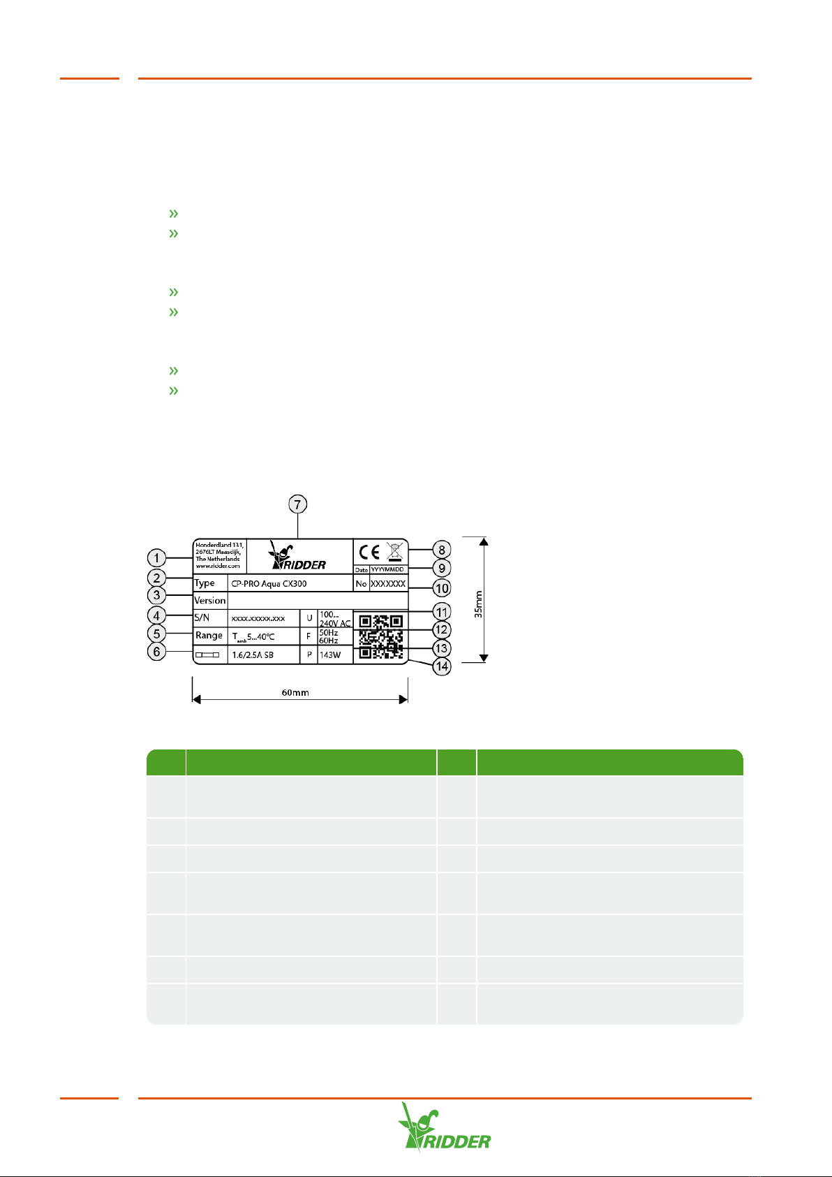
The type plates of some components also specify the version numbers of the software
installed.
1.2 How the Aqua CX300 works
The Aqua CX300 is designed to control irrigation and fertilizer application (collectively
called 'fertigation'). These processes are controlled based on a number of factors,
such the desired EC and pH levels in the irrigation water, and the amount of solar
radiation received by the plants. To maximize crop growth, these factors need to be
set at specific levels. These desired values (or 'setpoints') depend on a number of
variables, such as the crop variety, the time of day and the season.
Irrigation control is a process of continuous adjustment that is subject to a number of
external factors, such as the weather. To respond to these factors effectively, the
controller needs to be able to measure them. Examples of such measurements are
the EC level, pH level, solar radiation sum, flow rate and contact start level.
The controller calculates the actual control setpoints based on the difference between
the pre-set setpoints and the corresponding measured values. The controller uses
these calculated setpoints to control or operate the ‘corrective mechanisms’, such as
the irrigation unit or the valves.
1.3 Valve groups and valves
Valves can be assigned to valve groups in any combination. Each of these valve
groups can then be assigned to one of the pre-set irrigation programs. An irrigation
program is a group of settings that enable you to control the EC level (i.e. the
concentration of fertilizers) and pH level (i.e. the acidity) of the irrigation water
according to the precise needs of your crop. See also: "Programs" on page20.
A valve group consists of a number of valves. An irrigation percentage can be set for
each individual valve. Up to 160 valves can be divided among the valve groups. See
also: "Assign valves to group" on page16.
Up to six valves can be operated simultaneously. If both an irrigation program and
fogging program are active at the same time, this maximum will apply for both
programs in total. The following restrictions also apply:
the current of each output may not exceed 1 A;
the total current of each valve module side may not exceed 2 A;
the total current of all outputs in a system may not exceed 4 A (this value is
determined by the power supply).
1.4 Irrigation programs
Each irrigation program consists of a number of controls (e.g. Radiation Start, Contact
Start and Time Start). Each control, in turn, consists of a number of settings that
enable you to tailor irrigation (or fertigation) to your exact needs. For example, the
Radiation Start control includes the 'Radiation start active' and 'Start time of radiation
start' settings.
Aqua CX300
7

Only one irrigation program may be active at the same time. If another program is
triggered while an irrigation program is already active, the other program will be
queued until the active program has completed its irrigation cycle. The only exception
is a fogging program, which may be active at the same time as an irrigation program.
1.5 Start options
Irrigation can be started (and stopped) in a number of ways. For each valve group,
you can select from a manual start, six time starts, two cyclic starts, one contact start
and one radiation start.
Manual start: Activate a valve group manually.
Time start: Activate a valve group at the pre-set time, either every day or on a
specific day of the week.
Alternative time start: Activate a valve group once at the pre-set time or at
intervals of one or more days.
Cyclic start: Activate a valve group at regular intervals. A separate pause time
can be set for two daily periods.
Radiation start: Activate a valve group when the pre-set radiation sum is
reached.
Contact start: Activate a valve group when a contact signal is received. This
may be a signal from a fluid level sensor or humidity sensor, for instance.
Frost prevention start: Activate a valve group when the temperature drops
below the pre-set ground frost temperature.
If a valve group cannot be activated because another valve group is currently active,
the valve group will be queued. However, if a start condition of the valve group that is
currently active is met, the valve group will not be queued (with the exception of a
manual start).
1.6 EC and pH control
The Aqua CX300 can control the EC and pH levels of the irrigation water if equipped
with the EC and pH modules. These modules enable you to set the desired EC and pH
values (or 'EC and pH setpoints') for each valve group. Fertilizer application can be
automatically adjusted to raise or lower the EC value of the irrigation water based on
the solar radiation level. If the unit is equipped with an additional set of EC and pH
sensors, these can be used to monitor the measurements of the primary EC and pH
sensors (called the 'control' sensors). However, instead of monitoring the primary
sensor, a second EC sensor can also be used to measure the EC level of the supply
water. This value can then be used in the control program. The unit is able to dose (or
inject) fertilizers from multiple fertilizer tanks into the irrigation water according to
the pre-set ratios. The controller does this by operating the dosage valves.
1.7 Irrigation
The quantity of water applied per irrigation cycle can be set either by duration, or by a
volume in litres (the latter is only possible if a flow rate meter is present).
Aqua CX300
8

Pre-rinsing or post-rinsing of the crop can be programmed either by the duration that
rinsing should last, or by a volume in litres.
A time+volume can also be set for both irrigation and rinsing. This means that
irrigation or rinsing will stop once the pre-set volume is reached, or sooner if the pre-
set time has elapsed.
1.8 General
General settings are parameters that usually do not need to be changed once they
have been set. These are the basic controller settings, such as the type of EC and pH
control, degrees of longitude and latitude, and the number of valves present.
1.9 Type of irrigation
An irrigation program can be used for either irrigation or fogging. If the program is
used for irrigation, EC and pH control (if present) will become available and a system
pump output will be enabled. If the program is used for fogging, only an auxiliary
output will be enabled. Only one valve group for irrigation and one valve group for
fogging may be active at the same time.
Aqua CX300
9

2 Operation
2.1 Switching on the controller
The main switch (Power ON/OFF) is located on the left side of the computer housing.
This switch enables you to turn the mains supply to the controller on and off. When
you switch the controller on for the first time, all the settings are configured to the
factory defaults. Changes made to the settings are stored in the controller's memory.
The settings will be retained if the controller is switched off. To reset all settings back
to their factory defaults, press and hold down push button 1 on the display board while
switching on the controller.
2.2 Keyboard
Figure 2-1 Keyboard
Character Meaning Use
A Numeric
keys
Keys for adjusting the values of settings.
B Negative
value
Minus sign, for entering negative numbers.
C Decimal
value
Decimal point, for entering decimal values.
D Delete Delete the value entered.
Return to the previous menu.
E Enter To adjust a setting: Press Enter (E) to select the setting.
Then enter the new value. To save this value, press
Enter (E). To restore the original value of the setting,
press Delete (D).
F Help (?) Press this key to display a description of the menu or
setting selected. To return to the previous screen, press
Delete (D).
Aqua CX300
10

Character Meaning Use
G Start To manually activate a valve group:
Press Start (G).
Use the arrow keys to select the desired valve
group.
Press Enter (E). The main data of the irrigation
program assigned to the valve group appear on
the display. You can modify any of this data and
store the changes in the irrigation program.
If the settings are in order, select OK and press
Enter (E). You return to the previous menu (where
you can select a new valve group). A message
also appears stating that the group has been
activated. To clear this message, press Delete
(D).
To return to the previous menu, press Delete (D).
When an alarm message or pause is triggered, use the
Start (G) key to resume irrigation once the cause of the
alarm has been removed:
Press Start (G),
Select the desired valve group,
Press Enter (E).
H Pause
button
To manually pause an active valve group:
Press Pause (H).
If the fogging program is also active, you are
asked which program you want to pause. Use the
arrow keys to select the desired valve group.
Press Enter (E). The valve group interrupts its
irrigation or fogging program. When the valve
group is reactivated, the corresponding irrigation
or fogging program will resume. An active valve
group is also paused if certain alarm messages
are triggered. Also see: Start (G)
I Stop To manually deactivate an active valve group:
Press Stop (I).
If the fogging program is also active, you are
asked which program you want to stop. Use the
arrow keys to select the desired valve group.
Press Enter (E). The valve group stops irrigating
and the controller moves on to the next valve
group in the start queue.
Aqua CX300
11

Character Meaning Use
J ^ - v (arrow
up and
down)
Select a different line/value
In menus: go to another line on the display.
When adjusting a setting: select a different option.
< - > Move horizontally
Move the cursor left or right along the line.
K Valve menu Press this key to display the valve menu. In this menu,
use the '(De)activate valves' key (L) to activate or
deactivate valves. When finished, select OK and then
press Enter (E). To return to the main menu, press
Delete (D). Your changes are saved.
L (De)activate
valves
After opening the valve menu by pressing the 'Valve
menu' key (K), use the '(De)activate valves' key (L) to
activate or deactivate valves. This key works like an
on/off switch. To return to the main menu, press Delete
(D). Your changes are saved.
M Main menu Go directly to the main menu.
2.3 Displaying data and entering settings
The Aqua CX300 is equipped with up to 10 irrigation programs, each of which can be
configured independently. An irrigation program enables you to set the various
control parameters for irrigation. Each valve group is assigned to an irrigation
program.
2.3.1 Displaying data
Various summaries are available that display information about the valve groups,
such as measurements, activities and start data. When a valve group summary is
displayed, you can use the arrow keys to select the next valve group.
2.3.2 Entering settings
Use the up and down arrow keys to move the selection bar onto the menu and the
setting that you want to select. Press E to confirm your selection.
To display help, press ?.
When you have selected the desired setting, press E. The selection bar move onto the
input field.
Use the numeric keys to enter a new value, or use the up and down arrow keys to
select one of the options.
If the input field has several sections (e.g. when setting a time), use the left and right
arrow keys to move the cursor horizontally.
Aqua CX300
12

When you have entered the correct values, press E. The new value is stored in the
memory.
2.3.3 Alarms
If a detectable error situation occurs, an alarm message will be triggered. A number
of alarms will result in the irrigation group being paused. To acknowledge an alarm,
press the <Delete> key. After resolving the error situation, you can resume a paused
irrigation group by initiating a manual start.
Aqua CX300
13

3 Settings
3.1 Arrangement of settings and readouts
Menu
Main menu 3.2
Settings 3.3
Programs 3.3.1
P01 - P10 3.3.1.1 - 3.3.1.13
Irrigation
EC control
EC pre-blending
pH control
Pre-mix unit
Time start
Alternative time
start
Cyclic start
Contact start
Radiation start
Frost prevention
sprinkling
Weather influences
Program
characteristics
General 3.3.2 3.3.2.1 - 3.3.2.6
Program names
Group names
System settings
Weather
configuration
Aqua CX300
14

Menu
Water
configuration
Communication
Synopta settings
Registration
I/O
Modules
Measurements
Filter flushing
Flow rate
measurement
Assign contact
start
EC calibration
pH calibration
Backup settings
Assign valves to
group 3.3
Setting valves
3.3.3
Assign group to
program 3.4
(De)activate valves
3.5
Display summaries
4.1
Print summaries 4.2
Control level 3.2
Access code 3.2
Due to the limited space on the display, the names of some settings and readouts in
Synopta and this user manual may differ from those shown on the display.
The menus, settings and readouts that are shown on the display also depend on the
unit model and the sensors that have been connected.
Aqua CX300
15

3.2 Main menu button
Settings
Assign group to program
(De)activate valves
Display summaries
Control level
Access code
Settings
See: "Settings" below.
Assign group to program
See: "Assign group to program" on page62.
(De)activate valves
See: "(De)activate valves" on page62.
Display summaries
Control level
This enables you to select the difficulty level of the controls:
1. Only frequently-used settings are visible,
2. + less frequently-used settings,
3. + program safeguards (monitoring) and program characteristics,
4. + system definitions.
Access code
Here you can change the access code that enables a higher control level to be
selected. The code consists of four digits.
3.3 Settings
Programs
General
Assign valves to group
Setting up valves
Programs
See: "Programs" on page20.
General
See: "General" on page45.
Aqua CX300
16

Assign valves to group
In the 'Assign valves to group' menu, you can assign or unassign valves using the
'Enter' key. To activate or deactivate valves, use the 'De(activate) valve' key.
The group to which a particular valve has been assigned is displayed next to the
selection screen on the right-hand side.
Use the arrow keys to move the cursor, and press the 'OK' key to confirm your
changes.
Assigning valves to two valve groups (Aqua CX300 v.6.0 or higher)
As from version 6.0, it is possible to assign valves to two valve groups. You can also
set the sequence in which valves open.
If a valve sequence is set and irrigation is applied with multiple valves
simultaneously, valves may only open simultaneously if they have the same sequence
number.
To enable the function for assigning valves to two valve groups, set ‘Assign valves to
2nd group’ to Yes.
Figure 3-1 Assigning valve to second group
To activate the function for setting the valve sequence, set ‘Set valve sequence’ to
Yes.
Figure 3-2 Setting valve sequence
You can assign valves using the Valve settings menu or the assign valves screen.
Aqua CX300
17

The figure below of the Valve settings screen shows that valve 1 has been assigned to
valve groups 3 and 4. Sequence number 10 has been set for the first valve group (i.e.
valve group 3) and sequence number 20 has been set for the second valve group (i.e.
valve group 4).
Figure 3-3 Sequence in second valve group
This looks as follows on the assign valves screen:
Figure 3-4 Selected valves
As you can see, valve 1 has first been assigned to valve group 3 and has then been
assigned to valve group 4. A valve sequence cannot be entered or displayed on this
screen.
To add a valve, place the cursor on the desired valve and then press <E>. Since a
valve can be assigned to two valve groups (so two settings), it is added to the first
available position. (This is value 0 on the Valve settings screen, and '1: G—’ is
displayed on the assign valves screen.)
To add the valve to the first or second position, press <1> or <2> . These positions
are important if you are going to set a valve sequence.
When valve group 3 is activated, the controller will open all the valves for which the
first and second valve group numbers are set to 3.
Aqua CX300
18

EXAMPLE
Vlv1 Vlv2 Vlv3 Vlv4 Vlv5 Vlv6 Vlv7 Vlv8
First valve group
number
GR3 GR3 GR4 GR4 GR4
Second valve group
number
GR4 GR3 GR3
When Group 3 is activated, valves 1,2,5 and 6 will open to supply water.
To set a valve sequence, the ‘Set valve sequence’ function must first be enables on
the configuration screen. You can then enable the ‘Set valve sequence’ function for
each program individually.
Figure 3-5 Setting valve sequence
If you enable the ‘Set valve sequence’ function, the controller will use the ‘Sequence
in first valve group’ for the first valve group number and the ‘Sequence in second
valve group’ for the second valve group number.
Vlv1 Vlv2 Vlv3 Vlv4 Vlv5 Vlv6 Vlv7 Vlv8
First valve group
number
GR3 GR3 GR4 GR4 GR4
Second valve group
number
GR4 GR3 GR3
Sequence in first
valve group
10 9 0 0 20 0 0 0 0 0
Sequence in second
valve group
20000070000
When Group 3 is activated, the valves will open to supply water in this sequence: 5, 6,
2, 1.
When Group 4 is activated, the valves will open to supply water in this sequence: 6, 7,
5.
Aqua CX300
19

See also: "(De)activate valves" on page62.
After assigning the desired valves to groups, open the 'Valve Percentage' submenu.
Valve percentage (%)
The percentage of the 'Irrigation time' or 'Irrigation volume' that the valve should
irrigate. Set the irrigation time and irrigation volume for each irrigation program
using the 'Irrigation' menu.
100%: The valve will supply the pre-set irrigation volume, or will open for the
pre-set irrigation time.
150%: The valve will supply one and a half times the pre-set irrigation volume,
or will open for one and a half times the pre-set irrigation time.
50%: The valve will supply half the pre-set irrigation volume, or will open for
half of the pre-set irrigation time.
Setting valves
See 3.3.3
3.3.1 Programs
Each of the three programs (expandable to 10) contains the following menu:
Irrigation, see "Irrigation" below.
EC control, see "EC control" on page23.
EC pre-blending, see "EC pre-blending" on page28.
pH control, see "pH control" on page29.
Unit pre-mixing, see "Pre-mix unit" on page33.
Time start, see "Time start" on page34.
Alternative time start, see "Alternative time start" on page35.
Cyclic start, see "Cyclic start" on page36.
Contact start, see "Contact start" on page37.
Radiation start, see "Radiation start" on page39.
Frost prevention sprinkling, see "Frost prevention sprinkling" on page40.
Weather influences, see "Weather influences" on page42.
Program characteristics, see "Program characteristics" on page43.
3.3.1.1 Irrigation
The duration of an irrigation cycle is set in the following order:
Hours:minutes:seconds. If a litre counter is present, an irrigation cycle can also be
set in litres.Pre- and post-rinsing is set in time and/or litres, depending on whether a
litre counter is present.
An irrigation cycle can be started manually via the Synopta menu (if Synopta is
present) or by pressing the following button on the control cabinet:
Figure 3-6 The <Start> button
Aqua CX300
20
Table of contents
Other Ridder Farm Equipment manuals
Popular Farm Equipment manuals by other brands

Moultrie
Moultrie Ranch Series instructions

McFarlane
McFarlane Reel Disk 4100 Series Operation and parts manual

Original Tractor Cabs
Original Tractor Cabs 1695613 installation instructions

horsch
horsch Terrano GX Series operating instructions

Worksaver
Worksaver SSGR-84 Owner's and operator's manual

Tarmo
Tarmo TAR102 instruction manual

Agria
Agria 9600-112 Translation of the original operating instructions

Remlinger
Remlinger 700 Series owner's manual

Stara
Stara 14000 TRAILER Instructions and parts manual

Unverferth
Unverferth NutriMax EQUALIZER manual

Redexim
Redexim Level-Spike 1700 Operator and parts manual

Chapin
Chapin CARRY ALL 6400 use and care manual