Ridder SynCore RW Unit User manual
265341EN - 2021.06 - V01
Original product-manual
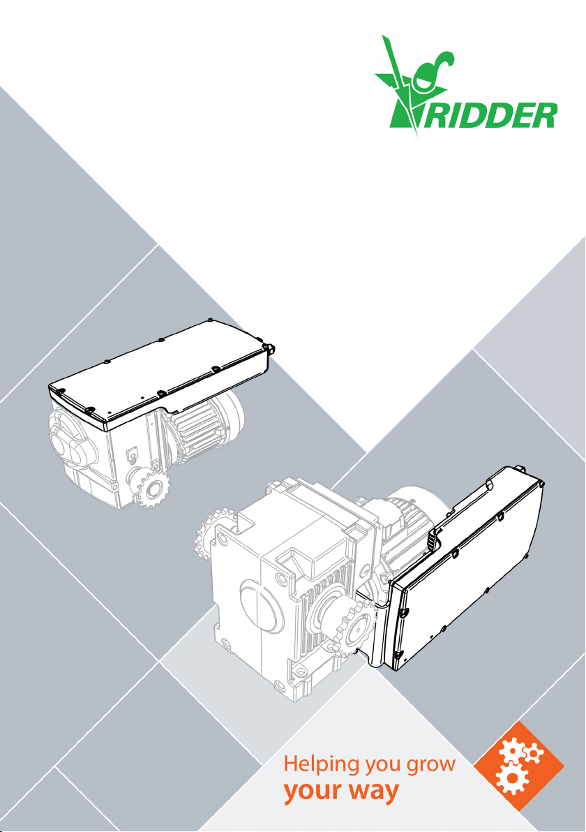
Ridder SynCore RW Unit
Product Manual
Lorentzstraat 32
3846 AX Harderwijk
PO Box 360
3840 AJ Harderwijk
the Netherlands
T+31 (0)341 416 854
F+31 (0)341 416 611
Iridder.com
Einfo@ridder.com
Ridder Drive Systems B.V.

TABLE OF CONTENTS
1. GUIDELINES, STANDARDS AND CONDITIONS
1.1 Applicable guidelines and standards 3
1.2 Approved personnel 3
1.3 Warning about discouraged use 3
1.4 Warranty provisions 3
2. SAFETY, PRECAUTIONS AND SYMBOLS
2.1 Signal words, instrucons and warnings 4
2.2 Precauons and safety instrucons 4
2.3 Residual risks 6
2.4 Symbols and abbreviaons 6
3. PRODUCT DETAILS
3.1 Idencaon 7
3.2 Descripon 8
3.3 Applicaon 9
3.4 Dimensions 9
3.5 Technical specicaons 10
4. INSTALL INSTRUCTIONS
4.1 Special tools and equipment 12
4.2 Installaon 13
5. CONNECT INSTRUCTIONS
5.1 Removal cover 13
5.2 Electrical material 14
5.3 Protecon - Condions and starng points 14
5.4 Overview and funcon diagram 15
5.5 Wiring diagram: Control board (RCB) 15
5.6 3-phase electric motor (208-600 VAC) 16
5.7 1-phase 3-wire electric motor (115-230 VAC) 17
5.8 1-phase 5-wire electric motor (115-230 VAC) 17
5.9 OPTIONAL - Fault contacts [SynCore RW Unit] 18
6. USER INSTRUCTIONS
6.1 Usage - Condions and starng points 19
6.2 Status LEDs 20
6.3 Operaon 20
6.4 Fault contacts 20
6.5 Safety funcons and stop funcons 21
7. COMMISSIONING INSTRUCTIONS
7.1 Commissioning - Condions and starng points 21
7.2 Check: Control direcon of the Automac Control (ACS) 22
7.3 Installaon cover 22
8. MAINTENANCE INSTRUCTIONS
8.1 Maintenance 23
9. SERVICE
9.1 Troubleshoong 23
9.2 Blink codes 24
9.3 Technical support 25
10. ENVIRONMENT
10.1 Decommissioning and removal 26
10.2 Waste disposal 27
Ridder Drive Systems B.V.
T+31 (0)341 416 854 - F+31 (0)341 416 611 - Iridder.com
2
1. GUIDELINES, STANDARDS AND CONDITIONS
1.1 Applicable guidelines and standards
This product complies with the provisions of the European guidelines that follow:
Machinery Direcve 2006/42/EC | Low Voltage Direcve 2006/95/EC
The harmonized standards (or parts of these standards) that follow are applicable:
NEN-EN-ISO 12100:2010 | NEN-EN-IEC 60204-1 |
NEN 82079-1 (62079: 2001) | NEN5509 | ISO 3864-2
Make sure that this product is only put into operation if the system (in which it will be installed)
complies with the provisions of the applicable standards and guidelines.
1.2 Approved personnel
This product manual contains important informaon for installers about the installaon and
commissioning of a Ridder SynCore RW Unit. Read this product manual and instrucons rst before
the work starts. Approved mechanical and/or electrical installers, with professional competence,
must do all work safely and responsibly.
TARGET GROUP FOR EACH CHAPTER CHAPTER (refer to Table of Contents)
TARGET GROUP 1 2 3 4 5 6 7 8 9 10
User (operator) • • • • (•)
Installer / Approved personnel • • • • • • • • • •
(•) = Not fully applicable (for users/operators)
Keep this product manual with the product during the lifespan. Make sure it is available for users
(operators), installers and approved personnel.
1.3 Warning about discouraged use
The condions that follow are applicable:
• Do not change (the construcon of) the SynCore RW Unit.
• It is not permied to use the SynCore RW unit to li or move people.
• Do not let the torque of the motor gearbox be more than its maximum.
• Do not let the duty cycle of the motor gearbox be more than its maximum.
• It is not permied to use the SynCore RW unit in operang condions, systems or conguraons
which do not comply with the technical specicaons (in this manual). Also refer to §3.5.
• Do not use SynCore RW units for other alternaves than screen systems.
• Do not connect more than four SynCore RW units to 2–4 RW conguraons, or more than six to
5–6 RW conguraons.
Refer to §3.3 for a descripon of the intended use.
1.4 Warranty provisions
For the warranty period and condions refer to the ‘Condions’ secon on our website at
ridder.com, or in the Ridder catalog.
Regulatory Conformity
Ridder Drive Systems B.V.
T+31 (0)341 416 854 - F+31 (0)341 416 611 - Iridder.com
3

2. SAFETY, PRECAUTIONS AND SYMBOLS
2.1 Signal words, instrucons and warnings
Signal words (ISO 3864-2)
This product manual contains safety instrucons with dierent signal words. The list that follows
gives the risk levels and possible eects of each signal word.
Instrucons and warnings on the product
Read the product manual to fully know all product properes,
before it is used or work starts!
Ê
It is not permied to use high-pressure cleaners (and related
cleaning agents)! Use a so brush with a small quanty of water
without cleaning agents.
Warning - Electrical voltage
Aer installaon interchange the plug in the highest posion
with the vent plug! Refer to the permied mounng posions in
the product manual.*
* Not applicable to motor gearboxes lled with grease!
2.2 Precauons and safety instrucons
Precauons
GENERAL
A system can be dangerous. Safety precauons and instrucons are important.
• If these precauons cannot be obeyed, then use warnings.
Suggeson to perform an operaon more eecvely.
May result in damage or problems if an acon is performed
incorrectly.
May result in minor injury if the hazard is not avoided.
Signicant injury, possible death, if the hazard is not avoided.
Severe injury and possible death if the hazard is not avoided.
Ridder Drive Systems B.V.
T+31 (0)341 416 854 - F+31 (0)341 416 611 - Iridder.com
4
• The responsibility for precauons and warnings lies with the installer of the system. Refer to the,
local or naonal, laws and regulaons of the country if a cercaon (mark) is necessary.
• Parts of the electrical or electronic installaons are connected to dangerous electrical voltages.
Work without professional competence or not obeyed warning instrucons could cause injury
and/or material damage.
• Ridder is not responsible for injury, material damage or consequenal damage if accessories are
used that Ridder did not make.
TRANSPORT, STORAGE AND PACKAGING
The condions and instrucons that follow are applicable.
• Ambient temperature: -15 to +60 °C (+5 to +140 °F).
• Ambient: A not-condensed relave humidity is necessary.
• Do a check for transport damage and missing parts immediately on incoming goods.
• Tell damages and missing parts immediately to the transport company and to your local Aer
Sales contact person.
• Do not use damaged products and if necessary do not start the work.
• Do not remove the product from the (sealed) packaging before it is sent to the installaon site.
This prevents damage (from mechanical shocks) to the product.
• Use applicable means-of-transport with dimensions which are sucient. Use (if necessary) the
correct work equipment and accessories. Refer to “Dimensions” and “Technical specicaons”.
Make sure that the working condions comply with the, local or naonal, laws and regulaons.
• Make sure that storage areas and the areas in the means-of-transport are dry and the airow is
sucient.
• Make sure that the products do not touch the (moist) boom surface of storage areas and of the
means-of-transport (use pallets or such). The boom surfaces must be smooth.
• Make sure that the products are protected from dust, dirt and direct sunlight.
• Apply an applicable corrosion-prevenve agent to metal surfaces that are not painted.
• Aer installaon discard the packaging and obey the applicable naonal and/or local regulaons.
Safety instrucons
• Use (if applicable) personal protecve-equipment for protecon which agrees with the dierent
types of work.
• Do not let persons and not approved personnel be near controls and systems in operaon.
• Damaged systems must be stopped immediately unl they are repaired.
• Use safety barriers for system parts that move. Refer to the applicable standards and guidelines.
• The safety distance to the danger zone (if applicable) must agree with applicable standards and
guidelines (for example ISO 13857:2008).
• Do not operate systems when the motor gearbox (internally and/or externally) is frozen in cold
and moist condions (for example because of snow or ice).
• Do not operate systems when persons are in the danger zone and can touch the system.
If you do not obey the safety instrucons that follow it can be
dangerous and cause injury.
Ridder Drive Systems B.V.
T+31 (0)341 416 854 - F+31 (0)341 416 611 - Iridder.com
5

• Monitor the danger zone when you work with or near the system.
• Stop and de-energize systems during maintenance and cleaning work on or near the system.
• Make sure that there is sucient space between parts that move and adjacent objects.
• Stay away from or safety areas where there is a risk to become caught in a system that moves.
• The torque and the duty cycle of the system must be in the range of the motor gearbox
parameters. Refer to the product manual of the used Ridder motor gearbox at ridder.com.
2.3 Residual risks
Automac controls
The Ridder drive-units are usually used in automac controlled systems. Persons who do work or
stay near the system must know about that. If persons or their clothes touch the system during
operaon, it can be dangerous.
Forces
Ridder cannot be sure that there will be no injury to persons or damage to the system because of
the forces in the systems (in which the drive unit is installed).
2.4 Symbols and abbreviaons
This secon tells about used symbols and abbreviaons in this manual. The table that follows gives
the descripons.
Symbol Description Symbol Description
1L1 Power IN (A2) MCS Manual Control Screen
3L2 Power IN (A2) MPCB Motor-Protecon Circuit-Breaker
5L3 Power IN (A2) N Neutral wire
2T1 Power OUT (EM) PE Protecve earth
4T2 Power OUT (EM) PLC PLC control
6T3 Power OUT (EM) PTC PTC thermistor
ACS Automac control-system RCB Ridder control-board
A1 RW unit housing REU Ridder Encoder Unit
A2 Control board RLS Limit-switch system
D1 Status LED - Green RPU Digital posioning-meter
D2 Status LED - Red RSU Limit-switch system
D3 Status LED - Red RW Motor gearbox
D4 Status LED - Red X1 Power input (RCB)
EM, M Electric motor, Motor X2 Power output (EM)
EMC Electromagnec compability X3 Transformer
ES11,ES12 Duty switch RSU/RLS X4 PTC input
ES21,ES22 Safety switch RSU/RLS X5 Fault-contact output
Persons can be in danger of life if they touch a system that is in
operaon.
Ridder Drive Systems B.V.
T+31 (0)341 416 854 - F+31 (0)341 416 611 - Iridder.com
6

GND Ground X6 Automac-control input
ICurrent in Amperes (A) X7 RPU reference-input
L1, L2, L3 Voltage source X8 Manual-control input
MC Manual Control (external) X9 Limit-switch input
3. PRODUCT DETAILS
3.1 Idencaon
EXAMPLE
Ê
This product manual is only applicable to:
• Ridder SynCore RW Unit
• Serial numbers from 200.900.000
• Item numbers from 500000.
Idencaon is possible from the scker on the locaon shown. Refer
to the explanaon that follows on how to read the informaon. For
more informaon on item numbers and models refer to the Ridder
catalog or website at ridder.com.
RW1400: RW1000/1400, RW1200/1600S or RW2000S
1F: 1~ mains voltage
Alternatives
1-3F: - 1~ mains voltage (3-wire electric motor)
- 3~ mains voltage
3F: 3~ mains voltage
Alternatives
115-400: Mains voltage 115 V/230 V (1~) or 208 V/400 V (3~)
SYNCORE: Designaon Ridder Synchronized-Run systems (PLC control)
1~ = 1-phase
Note: SynCore conguraons are not possible/permied with RW70–200 motor gearboxes.
No symbol in idencaon = RW45, RW240/400/600 or RW800
3~ = 3-phase
400: Mains voltage 400 V (3~)
440-600: Mains voltage 440 V, 480 V or 600 V (3~)
Alternatives
RW UNIT: General designaon Ridder SynCore RW units
5D: 5-wire electric motor
No symbol in idencaon = 3-wire electric motor
Alternatives
Ridder Drive Systems B.V.
T+31 (0)341 416 854 - F+31 (0)341 416 611 - Iridder.com
7
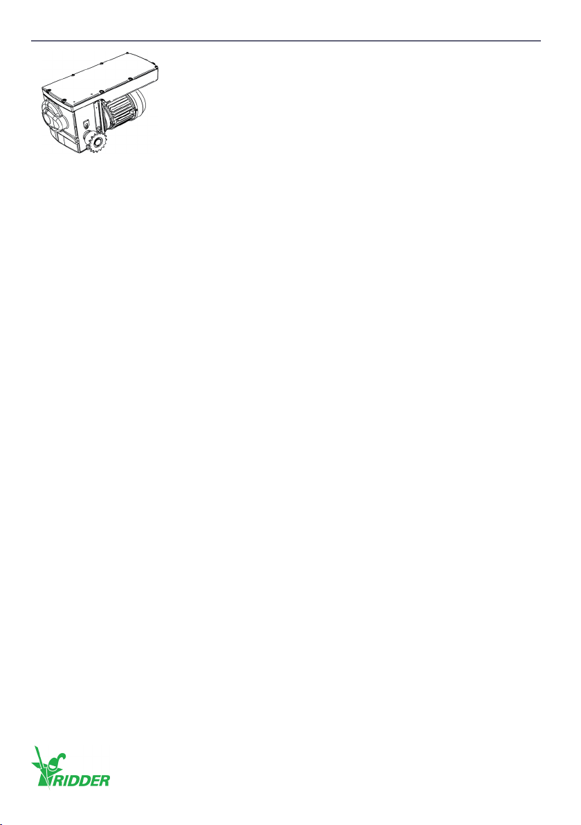
3.2 Descripon
SynCore RW units are applicable to synchronized control of screen
systems with a maximum of six Ridder RW motor gearboxes. The
RW unit is part of drive units with motor gearboxes type RW45,
RW240/400/600, RW800, RW1000/1400, RW1200/1600S or RW2000S.
The RW unit is applicable to:
• Dierent supply voltages
• Dierent mains frequencies
• 3-phase and 1-phase voltages.
The RW unit has a control board with a microprocessor and a semiconductor relay.
The control board has connecons for:
• The supply voltage
• The power supply for the electric motor (EM)
• An automac control signal (24 V AC/DC) from an automac control-system (ACS)
• A fault contact (NC)
• The PTC thermistor in the electric motor (EM) (if applicable) for thermal protecon.
The limit-switch system is also connected to the control board of the RW unit.
The SynCore RW unit transmits control signals from the automac control-system (ACS) and
monitors if these are processed without malfuncons. The RW unit has rotaonal-eld detecon
and phase detecon of the supply voltage.
The 24 V AC/DC control input is protected from:
• Control in two direcons at the same me
• Sudden changes of direcon.
The RW unit has status LEDs to show error messages of the system.
The SynCore RW unit has plug connectors and terminal strips to connect the cables. To pull the
cables through, out of the housing, the RW unit also has cable glands. The protecon rang of the
RW unit housing is IP54.
Opmerking: SynCore conguraons are not possible/permied with RW200 motor gearboxes!
Ridder Drive Systems B.V.
T+31 (0)341 416 854 - F+31 (0)341 416 611 - Iridder.com
8
3.3 Applicaon
The SynCore RW Unit is installed, as part of a drive unit, on dierent RW motor gearboxes. The RW
unit is used to control the motor gearboxes in two direcons-of-rotaon.
The SynCore RW Unit (on dierent RW motor gearboxes) is only applicable to screen systems.
For other (dierent) applicaons, approval from Ridder Drive Systems is necessary.
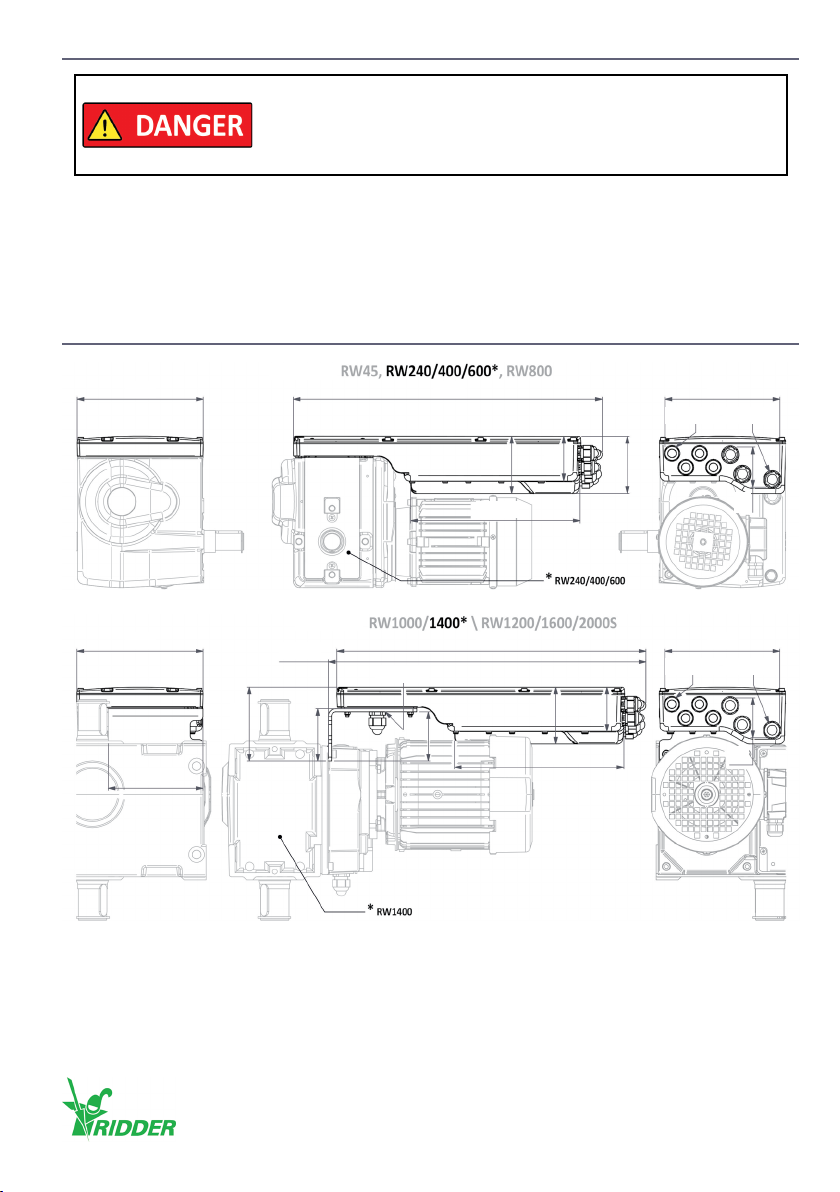
3.4 Dimensions
Note: The dimensions and illustraons are approximate. In this product manual shown illustraons
can be dierent than the components and/or systems.
Make sure that (with RW motor gearboxes) operated systems comply
with the provisions of the applicable safety standards and safety
guidelines. This prevents (for example) the risk to become caught in
a system that moves.
M16(4x)
200
90
64
90
70
490 182
268.5
M20(3x)
Example:
M16(4x)
200
64
90
70
490 182
268.5
M20(3x)
Example:
M20(1x)
503.5
117
83
78
150
Ridder Drive Systems B.V.
T+31 (0)341 416 854 - F+31 (0)341 416 611 - Iridder.com
9

3.5 Technical specicaons
Mechanical
Dimensions (WxHxD) RW45\RW240–600\RW800: 490 mm x 90 mm x 200 mm
RW1000–2000: 503.5 mm x 117 mm x 200 mm
Weight 3.1–5.4 kg
Ambient
Protecon rang IP54
Ambient temperature 0 to +60 °C (+32 to +140 °F)
Maximum relave humidity 95%
The three types of control boards (RCB) that follow
are available for the SynCore RW unit.
RCB-A (Type A):
50/60 Hz AC
1~ 115V-230 V, 12FLA, 72 LRA
3~ 208-400 V, 12 FLA, 72 LRA
RCB-B (Type B):
50/60 Hz AC
3~ 400 V, 10 FLA, 60 LRA
RCB-C (Type C):
50/60 Hz AC
3~ 440-600 V, 10 FLA, 60 LRA
Refer to the table that follows for abbreviaons,
technical specicaons and descripons of all
connecons.
Ridder Drive Systems B.V.
T+31 (0)341 416 854 - F+31 (0)341 416 611 - Iridder.com
10
Table of contents
Other Ridder Farm Equipment manuals


Popular Farm Equipment manuals by other brands

Schaffert
Schaffert Rebounder Mounting instructions

Stocks AG
Stocks AG Fan Jet Pro Plus 65 Original Operating Manual and parts list

Cumberland
Cumberland Integra Feed-Link Installation and operation manual

BROWN
BROWN BDHP-1250 Owner's/operator's manual

Molon
Molon BCS operating instructions

Vaderstad
Vaderstad Rapid Series instructions


