Ridder VitaLite-E User manual

SV 8.0
24/03/2020
96000006
Installation and User Manual
VitaLite-E and C

Ridder Growing Solutions B.V. Mailing address
Honderdland 131 Postbus 33
2676 LT Maasdijk 2676 ZG Maasdijk
The Netherlands The Netherlands
Tel: +31(0)15 3620300 Website: www.ridder.com
E-mail: info@gs.ridder.com, sales@gs.ridder.com,
helpdesk@gs.ridder.com
All efforts have been made to ensure the accuracy of the contents of this manual.
The above notwithstanding, Ridder Growing Solutions B.V. can assume no
responsibility for any errors in this manual or their possible consequences.
Should any errors be discovered, however, we would greatly appreciate being
informed of them.
This product is subject to the General Conditions of Ridder Growing Solutions
B.V.
This document may not be copied or made public by means of print, photocopy,
digital copy or any other process, without the prior written permission of Ridder
Growing Solutions B.V.
Publication date: 24/03/2020 11:32 Manual version number: 030 Item code:
96000006

Contents
1 Introduction to this manual 6
1.1 Introduction 6
1.2 Aims 6
1.3 Target groups 6
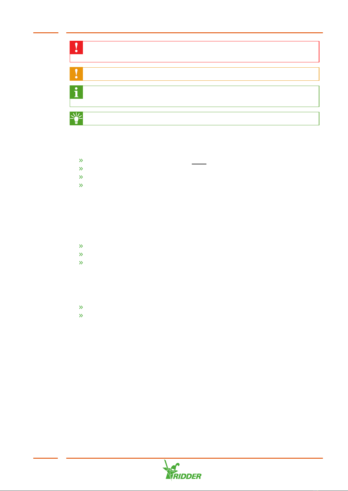
1.4 Symbols and annotations 6
1.5 Documentation overview 7
2 Product information 8
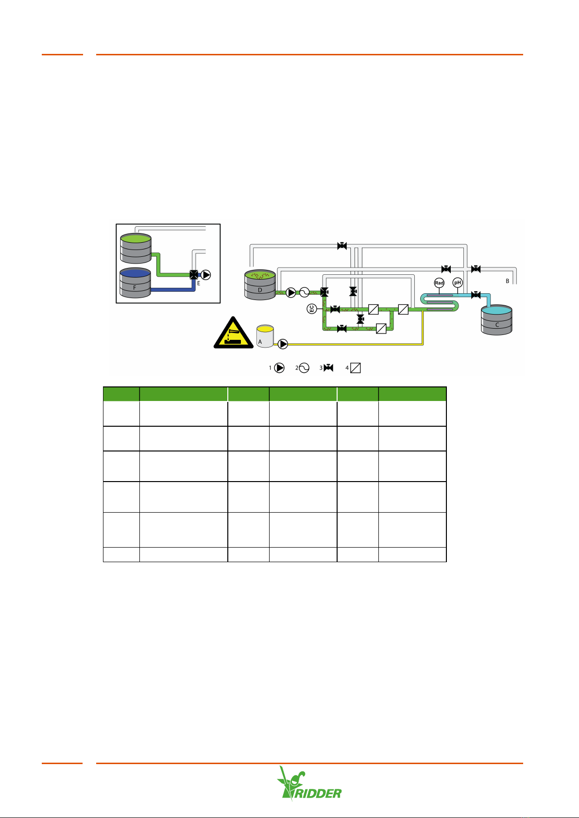
2.1 Schematic representation of the unit 8
2.2 Basic configuration 9
2.3 Description of I/O modules 9
2.3.1 Replacing I/O modules 10
2.3.2 Removing I/O modules 11
2.4 Intended use 12
2.5 Other product characteristics 12
2.5.1 Type plate 13
2.5.2 Quality control 13
2.5.3 Components, stickers and names 14
2.5.4 Certificates and declarations 16
2.5.5 Original Equipment Manufacturers (OEM) information 16
2.6 Packaging, storage and shipment 17
2.7 Recycling and disposal 17
3 Safety precautions and requirements 19
3.1 General safety requirements 19
3.2 Personal protective equipment 19
3.3 UV-C radiation 20
3.4 Chemicals 21
3.5 Emergency stop 21
4 Installation procedure 22
4.1 Installation requirements 22
4.1.1 Dealer/installer requirements 22
4.1.2 Installation requirements 22
4.1.3 Water installation requirements 24
4.1.4 Electrical installation requirements 24
4.1.5 Requirements for installing water tank sensors 24
4.2 Installation checklist 25
4.3 Connecting water components (water installation) 27
4.3.1 Pre-blending control (optional) 28
4.3.2 Filters 28
4.4 Connecting electrical components 29
4.5 Connecting acid dosing components 29
4.5.1 pH calibration 31
4.6 Connecting EC sensors (if present) 31
4.6.1 EC calibration 31
4.7 Installing quartz tubes and lamps 32
4.7.1 Installing quartz tubes 32
4.7.2 Quartz tube breakages 35
4.7.3 Pressurizing the unit 36
4.7.4 Installing UV-C lamps 37
4.8 Other installation work 38

4.8.1 Display board of the control panel 38
4.8.2 Connecting Synopta 40
5 Commissioning 41
5.1 Control panel 41
5.1.1 Reading out and setting variables 43
5.1.2 Alarms 43
5.2 Commissioning 44
5.2.1 Log in at dealer level 44
5.2.2 Check settings 44
5.2.3 Set start conditions 44
5.3 Testing the unit 44
5.3.1 Manually start disinfection 44
5.3.2 Manually start cleaning quartz tubes 46
5.3.3 Manually start filter flushing 47
5.4 Quality control 48
5.4.1 Sampling procedure for CFU testing 48
6 Operation 50
6.1 Power switch 50
6.2 System pump and dosing pump 50
6.3 Disinfection 51
6.3.1 Warming up UV lamps 52
6.3.2 Disinfection active 53
6.3.3 Stopping disinfection and post-flushing 53
6.4 Filter flushing 54
6.5 Cleaning quartz tubes 55
6.5.1 Dosing and circulating acid 55
6.5.2 Post-flushing after cleaning quartz tubes 56
7 Maintenance and quality control 57
7.1 Maintenance 57
7.2 Weekly maintenance 57
7.3 Monthly maintenance 57
7.4 Yearly maintenance 58
Appendix A:Control overview 59
8.1 General settings 59
8.1.1 System settings 60
8.2 System configuration 61
8.2.1 System activation 61
8.2.2 Identification 62
8.2.3 Protected settings 62
8.3 Communication 65
8.3.1 Console settings 65
8.3.2 IO bus settings 65
8.3.3 Synopta settings 65
8.3.4 Network settings 66
8.3.5 Modbus Settings 66
8.3.6 EC calibration 66
8.3.7 pH calibration 66
8.4 I/O 66
8.4.1 Modules 66
8.4.2 Control outputs 67
8.5 Backup settings 67

8.6 Unit 67
8.6.1 Control mode 67
8.6.2 Safeguards 68
8.6.3 Unit characteristics 69
8.7 Drain group settings 73
8.7.1 Warming up UV lamps 73
8.7.2 Start conditions 74
8.7.3 Period 76
8.7.4 Control 76
8.7.5 Drain groups / Safeguards 77
8.7.6 Drain groups / Drain group characteristics 80
8.7.7 Drain groups / Control characteristics 80
8.8 Cleaning quartz tubes settings 82
8.8.1 Cleaning quartz tubes / Control 83
8.8.2 Cleaning quartz tubes / Safeguards 85
8.8.3 Control characteristics 86
8.9 Filter flushing settings 86
8.9.1 Filter flushing / Control 86
8.9.2 Filter flushing / Safeguards 88
8.9.3 Filter flushing / Control characteristics 88
8.10 Water tank settings 88
8.10.1 Drain tanks 89
8.10.2 Disinfected tanks 90
8.11 UV lamps 91
Appendix B:Notifications 92
Appendix C:Wiring list 103
10.1 Output / pH module, Module ID: 1, Inputs & 4-20mA output 103
10.2 Output / pH module, Module ID: 1, Outputs 104
10.3 Output / Input module, Module ID: 2, Outputs 105
10.4 Output / Input module, Module ID: 2, Inputs 106
10.5 Output / Input module 5th - 8th drain group, Module ID: 3, Outputs107
10.6 Output / Input module 5th - 8th drain group, Module ID: 3, Inputs 108
10.7 EC Pre-Blending Module ID: 4 109

1 Introduction to this manual
Ridder Growing Solutions supplies both high-tech and simple solutions for large- and
small-scale horticulture companies. Ridder Growing Solutions‘s range is divided into
three product categories:
Water Treatment
Process Automation
Management Systems
The Ridder VitaLite is part of our range of water treatment products.
This is the installation and user manual for the VitaLite-E and C. This manual
was originally published in Dutch.
1.1 Introduction
The Ridder Growing SolutionsVitaLite-E and C is designed to disinfect drain water for
reuse as irrigation water in a horticultural environment.
1.2 Aims
This manual has two aims:
1. The manual describes how to install and connect the VitaLite-E and C.
2. This manual describes the functioning of the VitaLite-E and C and how to
maintain it.
1.3 Target groups
The manual has been written for two target groups:
the installers of the VitaLite-E and C
the users of the VitaLite-E and C
In general, installation will be carried out by the dealer of the VitaLite-E and C. This
manual uses the term ‘dealer’ to mean both the dealer and the installer.
The users are the growers, worldwide.
1.4 Symbols and annotations
This manual uses symbols, pictograms, abbreviations and annotations. This section
provides an overview of these.
1.4.1 Symbols
The following symbols are used:
VitaLite
6

Note: This notice provides important information or a warning. Ignoring this
information may result in product damage or personal injury.
Note: This notice provides important information or a warning.
Information: This notice provides additional information or a brief
explanation.
Tip: This relates to advice to users.
1.4.2 Notation methods
The following method of notation is used in the software user instructions:
A button is indicated as follows: the Start button.
A field is indicated as follows: the Connect string field.
A tab is indicated as follows: the Main tab.
A window is indicated as follows: the Log On window.
1.5 Documentation overview
This manual is part of a set of manuals included with the unit that was purchased.
Provided with every VitaLite-E and C model
Manual (this manual)
OEM manuals (original manuals of components such as pumps)
Electrical circuit diagrams
VitaLite-E and C Custom
Electrical circuit diagrams and accompanying documentation are included and depend
on the unit's configuration:
HortiMaX CX500 installation manual or
HortiMaX MultiMa installation manual
VitaLite
7

2 Product information
This section describes the components and the functioning of the VitaLite-E and C.
2.1 Schematic representation of the unit
Each unit is built according to the principles in the diagram below. There may be some
minor differences depending on the unit that you are installing.
No. Description No. Description No. Description
AAcid tank 1Pump EC EC sensor
(optional)
BDischarge pipe 2Litre counter Rad Radiation
sensor
CDisinfected
(water) tank
3Valve pH pH sensor
DDrain (water)
tank
4Filter
EPre-blending
system
(optional)
FFresh water tank
VitaLite
8

2.2 Basic configuration
A unit consists of at least the following components:
Figure 2-1: Basic configuration
No. Description No. Description
1Air bleed valve 13 Frame
2Pressure tank 14 Integrated controller (control
computer) and control panel
3Location of EC sensor 15 Ballast cabinet
4Disinfected water sampling tap 16 UV reactor
5Litre counter 17 pH sensor and monitor pH
sensor
6Drain water sampling tap 18 Radiation sensor
7Acid dosing point 19 Acid pump
8Bypass valve filter 20 Drain water return pipe
9Screen filter, two valves and two
pressure gauges for the screen
filter
21 Disinfected water outlet
10 Sight glass and pressure gauge of
system pump
22 Suction pipe (inlet)
11 Acid circulation valve 23 Discharge pipe
12 Sand filter with valves
2.3 Description of I/O modules
The VitaLite-E and C uses I/O modules from the Compactima series. A Compactima
module is a network node suitable for connecting peripheral equipment. You mount
the modules in the main cabinet or an expansion cabinet by simply clicking them into
place. Wires fitted with ferrules can be inserted into a module without any tools.
VitaLite
9

For a detailed technical description of the modules, please consult the insert provided.
Figure 2-2: A Compactima I/O module
General characteristics of the Compactima modules:
Technical data of all types
Width x height x depth 107.6 x 89.7 x 62.2 mm
Weight 0.191 kg
Mounting technique Mounting rail
Ambient temperature In operation: -25 ... 60ºC | storage / transport: -40 ... 70ºC
Air humidity In operation: 5 ... 95% | storage / transport:
Protection class IP20 according to IEC 60529/EN 60529
Power supply SC 24V
Documentation Insert Compactima Modules
2.3.1 Replacing I/O modules
Each I/O module has a unique ID. An ID can only be assigned using the integrated
controller on the unit.
Module Model ID
pH CX-DO16/pH2 1
I/O CX-DO16/AI16 2
EC CX-DO16/EC2 4
To assign a module ID, proceed as follows:
1. Press and hold down the two push buttons on the I/O module for ten seconds to
reset the I/O module. The LEDs on the right-hand side of the push buttons will
start flashing red. This means that the module has been reset, assigned node ID
255 and disconnected from the bus.
VitaLite
10

2. Press and hold down either of the push buttons again for two seconds; the four
LEDs on the right-hand side of the push buttons will light up continuously. This
means that the module has been reset and connected to the bus.
Only one module may be in this mode at the same time. The ID that you wish
to assign may not be in use by another module.
3. Go to: M Settings / General / I/O / Modules.
4. Select the module in question (using the right arrow button).
5. Select the line Assign ID and then press E. The result will appear on the
display. On the module, the four red LEDs on the right-hand side of the push
buttons will switch off.
The module's readout status will remain 'unreliable' until the controller has
restarted, see point 7 below.
6. Repeat this procedure for the other modules.
7. Next, shut down the VitaLite-E and C in the correct manner. To do this, press
and hold down push button 2 on the display board for three seconds. Wait until
LED 2 on the display board lights up orange.
8. Switch the system off and back on with the main switch.
2.3.2 Removing I/O modules
1. On the unit's display, go to: M Settings / General / I/O Modules.
2. Select the module that you wish to remove permanently using the left/right
arrow buttons.
3. From this menu, select: Remove module.
4. Next, the VitaLite-E and C should be shut down correctly. To do this, press and
hold down push button 2 on the display board for three seconds. Wait until LED 2
on the display board lights up orange. The controller is now switched off.
VitaLite
11

5. Switch off the unit.
6. Physically disconnect the module, and then remove it.
7. Switch the controller back on.
2.4 Intended use
The Ridder Growing Solutions VitaLite-E and C series is designed to disinfect drain
water with the aid of UV light in a horticultural environment.
The Ridder Growing Solutions VitaLite-E and C series and all its components have
been developed specifically for a horticultural environment. The equipment and
accompanying software must be used as delivered and are subject to the instructions
in the Ridder Growing Solutions documentation provided with the equipment and
software. Your warranty will be void if you fail to observe the instructions laid down
by Ridder Growing Solutions.
For other conditions of use, please refer to our General Conditions of Sale.
2.5 Other product characteristics
The VitaLite-E and C should include the following inspection certificates and stickers.
Type plate
Quality inspection sticker
Component stickers
Consult your order confirmation for the exact specifications of your product.
Retain a copy of the order confirmation with this manual; that way, you will
always have the right specifications to hand.
VitaLite
12

2.5.1 Type plate
Every modular component of the unit is provided with a type plate. Each type plate
contains the following information:
1 Honderdland
131
2676 LT
Maasdijk
Nederland
www.ridder.com
7
Date:YYYYMMDD
Type 2 XXXXXXXX 8
Version 3
S/N 4 U 9 12
Range 5 F 10
Fuse 6 P 11
1 Name and address of the manufacturer /
supplier and their logo
7 CE marking and removal logo
2 Type description 8 No...
3 Version 9 Voltage (U) in VAC
4 Device serial number 10 Frequency in Hz
5 Temperature range in °C 11 Power in watts
6 Fuse in amperes 12 QR code (optional)
The type plates of certain components also specify the version number of the
software installed.
2.5.2 Quality control
Every Ridder Growing Solutions unit is checked and tested for correct operation
before shipment. The corresponding certificate can be found in the documentation
included with the unit.
A control cabinet that passes our quality inspection is provided with the label below on
the inside of the cabinet. Please contact Ridder Growing Solutions if this label is
missing.
VitaLite
13

1
Inspected by:
2 Name:
3 Date
4 Sign
xxxxxxxx
DD/MM/JJ
xxxxxxxxx
1 Title and logo 3 Date inspected
2 Inspector name 4 Inspector signature
2.5.3 Components, stickers and names
The main components of the unit are provided with an identification sticker. The table
below describes the meaning of each sticker. Your system may not necessarily
include every sticker listed.
Sticker Term on
sticker
Translated
term
Description
Lamps
UVC UV-C
lamps
UV-C
lamps
UV-C reactor, tube containing UV-C lamp.
Pumps
PA Acid
dosing
pump
Acid
dosing
pump
Pump for dosing acid during the disinfection
process and the cleaning of the quartz tubes.
PFF Filter
flushing
pump
Filter
flushing
pump
Separate pump for flushing the sand filter.
PS System
pump
System
pump
Pump for pumping water to and from the tanks,
and through the system.
Tanks
SA Acid
container
Acid tank Tank for storing acid.
VitaLite
14

SDi1..4 Disinfected
water
storage
1,2,3,4
Disinfected
tanks
1,2,3,4
Tanks for storing the disinfected water.
SDr1..4 Drain
water
storage
1,2,3,4
Drain
tanks
1.2.3.4
Tanks for storing drain water.
SFr Fresh
water
storage
Fresh
water tank
Tanks for storing fresh water.
Filters
FSa1..3 Sand
filters
1,2,3
Sand
filters
1,2,3
Filter for removing suspended solids from the
water.
FSc Screen
filter
Screen
filter
Filter required behind the sand filter.
Valves
VAR Acid rinse
valve (acid
circulation
valve)
Acid
circulation
valve
Valve for circulating acid during the cleaning
process of the quartz tubes.
VDi1..4 Disinfected
valves
1,2,3,4
Disinfected
valves
1,2,3,4
Valves for directing disinfected water into the
disinfected tanks.
VDr1..4 Drain
valves
1,2,3,4
Drainklep
1,2,3,4
Valves for directing drain water into the drain
tanks.
VFB Filter
Bypass
valve
Filter
bypass
valve
Valve for diverting the acid so it will not pass
through the filters.
VFF1..3 Filter 1,2,3
Flushing
valves
Filter 1,2,3
flushing
valves
Valves for flushing the filter.
VPr Pre-
blending
valve
Pre-
blending
valve
Valve for controlling the ratio between drain
water and fresh water / rainwater.
VSu1..4 Supply
valves 1..4
Supply
valves 1..4
Valves for supplying water from a drain tank
into the unit.
VitaLite
15

VW Discharge
valve
Discharge
valve
Valve for discharging water into the sewer or a
tank.
Sensors
EC EC control
sensor
Control EC
sensor
Sensor for measuring the EC value of the drain
water blended with fresh water. This allows the
blending ratio between fresh water and drain
water to be controlled based on the EC value.
pH pH control
sensor
Control pH
sensor
Sensor for measuring the pH value of the water.
This allows the acidity of the water to be
controlled during the disinfection process and
the cleaning of the quartz tubes.
FDr Drain flow
sensor
Drain flow
sensor
Sensor for measuring the amount of drain
water.
FTo Total flow
sensor
Total flow
sensor
Sensor for measuring the total amount of
water. The total amount of water consists of a
ratio between fresh water and drain water.
LDi Disinfected
level
sensors
1..4
Disinfected
level
sensors
1..4
Sensors for measuring the amount of water in
the disinfected tanks.
LDr Drain level
sensors
1..4
Drain level
sensors
1..4
Sensors for measuring the amount of water in
the drain tanks.
Rad Radiation
sensor
Radiation
sensor
Sensor for measuring the UV-C radiation
intensity.
2.5.4 Certificates and declarations
The design and manufacture of the Ridder Growing Solutions VitaLite-E and C and
components supplied with it corresponds with the following standards:
CE directives
2014 / 30 / EU Electromagnetic Compatibility
2014 / 35 / EU Low Voltage Directive
CE standards
EN 61326-1:2013 EMC Emissions
EN 61326-1:2013 EMC Immunity
2.5.5 Original Equipment Manufacturers (OEM) information
Certain VitaLite-E and C components, such as the pump, are purchased from other
suppliers. Some of these components come with their own documentation. This
documentation is included with the unit. Please consult this documentation for the
correct use and maintenance of these components.
VitaLite
16

2.6 Packaging, storage and shipment
2.6.1 Packaging
The VitaLite-E and C is shipped in one or more large crates and includes a number of
boxes containing separate components.
2.6.2 Transport
To prevent damage during transport, certain components are shipped separately.
Make sure that these components are installed correctly.
Other information, such as temperature requirements, can be found in "Installation
requirements" on page22.
Please consider your own safety and that of others when loading, unloading and
moving the unit.
Be particularly mindful of the risk of the unit falling or sliding accidentally. Only
use vehicles that are suitable for transporting the VitaLite-E and C. Please take
into account the weight and centre of gravity of the VitaLite-E and C during
transport.
2.6.3 Storage
Store the product and the separate components in a dry and dust-free environment.
Do not expose products to direct sunlight. Keep the various components in their
original packaging for as long as possible. Section "Installation requirements" on
page22 provides a complete overview of the requirements for installing the VitaLite-E
and C.
Please also read the warning in section "pH calibration" on page31. This
warning applies specifically to the transport and storage of the pH sensor.
2.7 Recycling and disposal
When the VitaLite-E and C has reached the end of its service life, you should dispose
of it yourself.
Bear in mind that the pipes may still contain fertilizer residues.
Steps for pumping the pipes empty:
1. Pump the residual fertilizer into labelled containers.
2. Rinse the pipes with plenty of water.
3. Dispose of the containers in the prescribed manner.
VitaLite
17

Dispose of the containers in accordance with the applicable regulations in your
country. Consult the safety data sheets provided by the producers of the substances
or equipment you are disposing of and follow the safety instructions specified. Also
see the chapter "Safety precautions and requirements" on page19.
VitaLite
18

3 Safety precautions and requirements
When installing, using or removing the unit, please observe the safety precautions
and requirements listed below. See also: "Installation requirements" on page22.
3.1 General safety requirements
This unit is subject to the following general safety and regulatory requirements. See
also: "Installation requirements" on page22.
Before installation and use: read and understand the manual and
accompanying documents so that you are aware of the operating and safety
instructions.
Make sure that everyone who works with the unit is well-instructed and familiar
with the safety requirements.
Always take prompt and appropriate action in response to warnings and
notifications.
Replace broken or malfunctioning parts as soon as possible.
Only use original parts to perform repairs or replacements. Please refer to the
current price list.
It is not permitted to modify the system in any way. Unauthorized modifications
can cause serious harm to personnel, the unit or the crop.
3.2 Personal protective equipment
If applicable, use personal protective equipment (PPE), such as:
Icon Description
Safety boots
Safety goggles
Gloves
Protective clothing
Respiratory protection
VitaLite
19

Icon Description
Hearing protection
Safety helmet
3.3 UV-C radiation
UV-C radiation can severely damage unprotected skin and the retina of your eyes.
Avoid direct exposure to UV-C to prevent permanent injury.
Icon Description
Before maintenance work can be carried out on the unit, make sure that
the system's power supply has been disconnected and that the system's
water pressure has been removed.
Ultraviolet C radiation is harmful for your eyes and skin. Avoid direct and
indirect exposure to UV-C radiation!
After deactivation, the UV-C system and lamps will remain hot for a
considerable time. Let the system cool down for at least 10 minutes.
The stainless steel housing and the VitaLite-E and C's electronics must
always be grounded (earthed).
Wear suitable safety goggles or hood if you are working with an
operating UV-C lamp to prevent damage to your retinas and skin.
Never touch the quartz tubes or the UV-C lamps with your bare hands to
avoid fingerprints. The UV-C light will cause fingerprints to burn into the
glass, reducing the system's efficiency. Always use clean cotton or latex
gloves when handling the quartz tubes or UV-C lamps.
The UV-C lamps contain substances harmful to the environment. Dispose
of a broken UV-C lamp in accordance with local regulations (chemical
waste).
VitaLite
20
This manual suits for next models
1
Table of contents
Other Ridder Farm Equipment manuals