Ridder FertiMiXPro C User manual

SV 1.2
24/02/2020
96000025
Installation and User Manual
FertiMiX Pro C

Ridder Growing Solutions B.V. Mailing address
Honderdland 131 Postbus 33
2676 LT Maasdijk 2676 ZG Maasdijk
The Netherlands The Netherlands
Tel : +31(0)15 3620300 Website: www.ridder.com
E-mail: info@gs.ridder.com, sales@gs.ridder.com,
helpdesk@gs.ridder.com
All efforts have been made to ensure the accuracy of the contents of this manual.
Should any errors be discovered, however, Ridder Growing Solutions B.V. would
greatly appreciate being informed of them. Ridder Growing Solutions B.V. is
naturally very interested in your comments and additions.
This product is subject to the General Conditions of Ridder Growing Solutions
B.V.
This document may not be copied or made public by means of printing,
photocopying, digital copying or any other process, without the prior written
permission of Ridder Growing Solutions B.V.
Publication date: 24/02/2020 09:48 Manual version number: 010 Item code:
96000025

Contents
1 Introduction to this manual 5
1.1 Introduction 5
1.2 Aims 5
1.3 Target groups 5
1.4 Symbols and annotations 6
1.5 Documentation included 7
1.6 Disclaimer 8
2 Product information 9
2.1 Principles of operation 9
2.2 Process description 10
2.3 Product specifications 11
2.3.1 Basic configuration 11
2.3.2 Filling module 12
2.3.3 Pressure module with filter 13
2.3.4 Measurement module (sensors) 14
2.3.5 Dosing module 16
2.3.6 Pumps 18
2.3.7 Filters 18
2.3.8 I/O modules 19
2.4 Control 19
2.4.1 Ridder CX500 20
2.4.2 CX Assistant 20
2.4.3 Synopta 20
2.5 Individual components 20
2.5.1 Spare components and extra options 21
2.5.2 Peripheral equipment and accessories 21
2.6 Other product characteristics 22
2.6.1 Inspection plates 22
2.6.2 Quality control 23
2.6.3 Component stickers 24
2.6.4 Guidelines and standards 25
2.7 Packaging, storage and shipment 26
2.8 Recycling and disposal 27
3 Safety 28
3.1 General safety requirements 28
3.2 Chemical substances 28
3.3 Personal protective equipment 29
3.4 Emergency stop 29
4 Installation 30
4.1 Installation requirements 30
4.1.1 Dealer/installer requirements 30
4.1.2 Installation requirements 30
4.1.3 Water installation requirements 31
4.1.4 Electrical installation requirements 32
4.2 Step-by-step installation and commissioning instructions 32
4.3 Connecting water supply (hydronic installation) 33
4.4 Connecting electrical components 33
4.4.1 Connecting PC to FertiMiX Pro C / CX500 34

4.5 Installing other components 34
4.5.1 Connecting a dosing channel 34
4.5.2 Connecting EC sensor 35
4.5.3 Connecting pH sensor 35
4.5.4 Connecting the I/O modules 36
5 Commissioning 37
5.1 Updating software 37
5.2 Software configuration 38
5.2.1 Creating a configuration 38
5.2.2 Checking the configuration 41
5.2.3 Uploading the configuration 42
5.3 Software settings 44
5.3.1 Setting up fertigation 44
5.4 Calibrating the sensors 45
5.5 Pressurizing the FertiMiX 45
5.5.1 Step-by-step instructions 45
5.5.2 Water supply and pressure 46
5.6 Using the dosing channels for the first time 46
5.6.1 Even fertilizer dosing 47
5.7 Testing the FertiMiX 47
6 Operation 49
6.1 Power switch 49
6.2 Operating the system pump 49
6.3 Operation using Synopta (Quick Start) 50
6.3.1 Valve group 51
6.3.2 Assign valves to valve groups 51
6.3.3 Period 51
6.3.4 Fertigation recipes 52
6.3.5 Irrigation 52
6.3.6 Fertilizer dosing 53
6.3.7 Acid dosing 54
6.3.8 Filters 54
6.3.9 Start conditions 54
6.3.10 Alarms 55
7 Maintenance 56
7.1 Maintenance guidelines 56
7.2 Weekly maintenance 56
7.3 Monthly maintenance 56
7.4 Annual maintenance 57
Appendices 58
Glossary 58
Checklist for step-by-step installation procedure 60

1 Introduction to this manual
Ridder Growing Solutions supplies both high-tech and simple solutions for large- and
small-scale horticulture companies. Ridder Growing Solutions‘s range is divided into
three product categories:
Water Treatment
Process Automation
Management Systems
The Ridder FertiMiX is part of our range of water treatment products.
This is the installation and user manual for the FertiMiX Pro C. This manual
was originally published in Dutch.
1.1 Introduction
The FertiMiX Pro C doses water and fertilizers automatically via a mixing tank into the
main irrigation line (or main pipe). This is also known as a 'mixing tank fertigation
system'.
1.2 Aims
This manual has two aims:
1. The manual describes how to install and connect the FertiMiX Pro C.
2. This manual describes the functioning of the FertiMiX Pro C and how to maintain
it.
1.3 Target groups
The manual has been written for two target groups:
the installers of the FertiMiX Pro C
the users of the FertiMiX Pro C
In general, installation will be carried out by the dealer of the FertiMiX Pro C. This
manual uses the term ‘dealer’ to mean both the dealer and the installer.
The users are the growers, worldwide.
Ridder Growing Solutions advises both target groups to familiarize themselves with
the content of the entire manual:
Sections 4 and 5 have been written specifically for the dealers.
Sections 6 and 7 have been written specifically for the users.
FertiMiX
5

1.4 Symbols and annotations
This manual uses symbols, pictograms, abbreviations and annotations. This section
provides an overview of these.
1.4.1 Symbols
The following symbols are used:
Note: This notice provides important information or a warning. Ignoring this
information may result in product damage or personal injury.
Note: This notice provides important information or a warning.
Information: This notice provides additional information or a brief
explanation.
Tip: This relates to advice to users.
1.4.2 Pictograms
To show that personal protective equipment (PPE) is required, the following
pictograms are used:
Pictogram Name
Protective clothing
Gloves
Safety goggles
Safety boots
1.4.3 Abbreviations
This manual uses the following abbreviations:
Symbol Name
°C degrees Celsius
°F degrees Fahrenheit
cm centimetre
EC Electrical Conductivity
FertiMiX
6

Symbol Name
Hz Hertz
L (or l) litre
L/h litres per hour
m metre
max. maximum
min. minimum
ml millilitre
mS/cm millisiemens per centimetre
m3cubic metre
pH acidity
PPE personal protective equipment
V Volt
W x H x D width x height x depth
Where appropriate, these terms may be used in full the first time they are
mentioned, with the abbreviation shown in brackets. After that, the
abbreviation will be used.
1.4.4 Notation methods
The following method of notation is used in the software user instructions:
A button is indicated as follows: the Start button.
A field is indicated as follows: the Connect string field.
A tab is indicated as follows: the Main tab.
A window is indicated as follows: the Log On window.
Instructions are written between horizontal grey lines.
1.4.5 Glossary
A glossary has been included in the appendix (see Appendix: "Glossary" on page58).
1.5 Documentation included
The FertiMiX includes a full set of documentation. This manual is part of that
documentation. You will also find:
Additional information on, for example: pumps, measuring equipment, etc. can
be found in the Original Equipment Manufacturer (OEM) manuals, supplied
separately. Please consult these OEM manuals for the correct use and
maintenance of the relevant components.
Electrical wiring diagrams.
FertiMiX
7

1.6 Disclaimer
The FertiMiX Pro C series and all its components have been developed specifically for
a horticultural environment. The equipment and accompanying software must be used
as delivered and are subject to the instructions in the Ridder Growing Solutions
documentation provided with the equipment and software.
The FertiMiX Pro C series is designed for irrigation and fertigation applications in a
horticultural environment.
For other conditions of use, please refer to our General Conditions of Sale.
Your warranty will be void if you fail to observe the instructions provided by Ridder
Growing Solutions.
This manual describes the FertiMiX Pro C. Certain details of the FertiMiX Pro C that
you will be installing may vary from the situation shown. Please refer to the order
confirmation to check whether the FertiMiX Pro C provided has non-standard
specifications.
Ridder Growing Solutions has made every effort to provide up-to-date illustrations
and screenshots in this manual. However, the illustrations and screenshots used may
differ in some details from what you actually see. Screenshots have been made using
the English versions of Synopta and CX Assistant. For the latest version of the
screenshots, you will need to use the latest version of the Synopta and CX Assistant
software.
FertiMiX
8

2 Product information
This section describes the components and the functioning of the FertiMiX Pro C.
2.1 Principles of operation
Figure 2-1: Diagram showing the basic operation of the FertiMiX Pro C
No. Name No. Name
1 Fertilizers, acid, alkali (lye) or
other substances
9 Pressure pipe / filling pump
2 Dosing valve 10 EC sensor
3 Venturi 11 Filling valve with overflow
protection
4 EC sensor 12 Mixing tank
5 pH sensor 13 System pump
6 Clean water 14 Filter
7 Drain water 15 Flow meter
8 Filter 16 Valve groups and valves in the
greenhouse
FertiMiX
9

2.2 Process description
The FertiMiX works as follows:
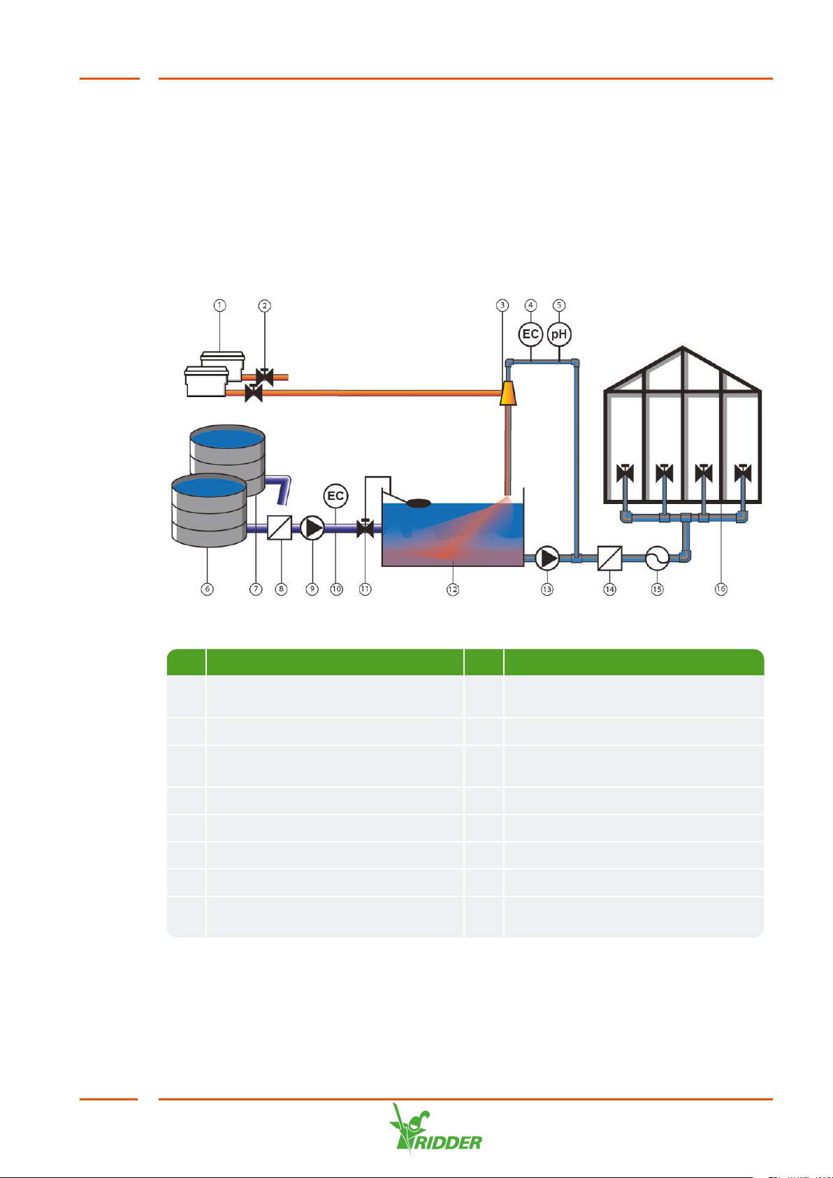
Fresh water is supplied (optionally pre-blended with drain water).
The supply pipe is fitted with:
(optionally) a filter for filtering water,
(if the pre-pressure is less than two bars) a filling pump for pumping
water into the mixing tank,
(optionally) an EC sensor for pre-blending control.
The water flows into the mixing tank via the filling module. The filling module
regulates the water supply to the mixing tank.
The system pump pumps the water from the mixing tank towards the pressure
module.
From the pressure module, the water is directed to the dosing module.
Some of the water flows to the measurement module. The measurement
module is a branch line where the EC and/or pH is measured.
A dosing module consists of one or more dosing channels. Each fertilizer (or
other additive) requires its own dosing channel equipped with a venturi.
Fertilizers (or other additives) are sucked out of the stock tanks connected to
the venturis.
The fertilizers and other additives are dosed using the dosing valves based on
the fertigation recipe.
From the dosing module and measurement module, the water is fed into the
mixing tank.
The design of the supply pipe creates a swirling motion in the mixing tank. This
swirling motion effectively mixes and aerates the water and fertilizers. This
ensures that the fertilizers dissolve completely and allows the equilibrium
reaction of the acid or alkali (lye) with the water to stabilize. This reaction
creates CO2gas. The residence time of the water inside the mixing tank plays a
key role in the mixing process. It also allows the CO2gas to escape from the
mixture, preventing gas bubbles from clogging the pipes.
A float and valve prevent the mixing tank from overflowing.
Once the water and fertilizers have been mixed sufficiently, the system pump
pumps the irrigation water from the mixing tank to the pressure module. This
module has a branch line for distributing the irrigation water.
The water flows to the irrigation valves and is then supplied to the crop. If
required, the water can first be filtered and the flow rate can be measured.
The entire process is controlled by the Ridder CX500 process controller. Its tasks
include:
ensuring that the correct fertigation recipe is prepared (proportion of fertilizers
and water).
controlling the valves to ensure that the water reaches the crop.
FertiMiX
10

2.3 Product specifications
The FertiMiX Pro C is available in various configurations, because different dosing
channels, pumps, sensors and I/O modules can be added to the FertiMiX Pro C. This is
described in this and the following sections.
2.3.1 Basic configuration
Figure 2-2 is a diagram of the components of the FertiMiX Pro C.
Figure 2-2: Side and front view of the FertiMiX Pro C
No. Description No. Description
1 Connection point for fresh water 9 Venturi (per dosing
module: min. of one
and max. of five)
2 Connection point for irrigation water distribution 10 Pressure regulator
3 Mixing tank 11 System pump
4 Screen filter for shut-off valve (in mixing tank) 12 Thermal cut-out for
pump (optional)
5 Dosing module (one dosing module consists of
min. of one and max. of five dosing channels for
fertilizers and, optionally, acid/alkali)
13 500-micron screen
filter
6 Water outlet of mixing tank 14 Power switch /
emergency stop
7 Filling module (located in mixing tank) 15 Control cabinet
8 pH measurement module (location of sensors)
FertiMiX
11

The following table provides an overview of the main specifications of the FertiMiX
Pro C basic configuration(s):
Component Specifications*
Nominal capacity at 4 bars 15 to 90 [m3/h]
Dimensions of frame (W x H x D) 120 x 160 x 120 [cm] smallest
280 x 160 x 200 [cm] largest
Dimensions of main cabinet (W x H x D) 60 x 140 x 30 [cm]
Mixing tank volume 250 to 1000 [L]
Electrical voltages and frequencies 3 x 400 [V], 50 [Hz], with neutral and
earth
3 x 400 [V], 60 [Hz], with neutral and
earth
3 x 230 [V], 50 [Hz], with earth
3 x 230 [V], 60 [Hz], with earth
3 x 440 [V], 60 [Hz], with earth
3 x 480 [V], 60 [Hz], with earth
3 x 600 [V], 60 [Hz], with earth
Power consumption Depends mainly on the type(s) of pump
(s)
Process controller CX500
User interface on the FertiMiX
(standalone)
No.
2.3.2 Filling module
The filling module is located directly after the connection point of the fresh water
supply.
If the water in the mixing tank rises too high, the float sends a signal to the shut-off
valve to shut off the water supply. You can also use the knob on the shut-off valve to
control the water supply to the mixing tank manually.
*Dependent on the configuration selected.
FertiMiX
12

Figure 2-3 Filling module in mixing tank
No. Description No. Description
1 Fresh water
inlet
3 Shut-off valve (with plastic rotary knob for manual
operation)
2 Float 4 Water inlet of mixing tank
2.3.3 Pressure module with filter
The pressure module guides the irrigation water to the dosing module with the
measurement module. The pressure module is equipped with a pressure regulator
that enables the pressure before the venturis (see section "Dosing module" on
page16) to be set to 2.2 bars. The pressure after the venturis is always 0 bars. The
screen filter in the pressure module prevents the venturis from clogging.
FertiMiX
13

Figure 2-4 Pressure module with filter
No. Description No. Description
1 Pressure gauge for system
pump
3 Pressure regulator
2 500-micron screen filter 4 Pressure gauge (0 - 6 bars) for filter (4
bars)
2.3.4 Measurement module (sensors)
The pH measurement module is located after the pressure module; it is a branch of
the supply channel of the dosing module. The pH measurement module is equipped
with the pH sensors; the EC sensors are located before the pressure module. After
passing through the pH measurement module, the water is returned to the mixing
tank.
FertiMiX
14

Figure 2-5 Location of pH measurement module and EC sensors
No. Description
1 pH measurement module
2 EC control sensor
3 EC verification sensor
Figure 2-6 pH measurement module
No. Description No. Description
1 Connection point from pressure module 3 pH verification sensor
2 pH control sensor 4 Return to mixing tank
FertiMiX
15

Depending on the configuration, the following sensors can be added:
EC sensor: the EC sensor measures the electrical conductivity of the water.
pH sensor: the pH sensor measures the acidity level of the water.
The FertiMiX Pro C is supplied with at least one EC sensor as standard.
If one EC / pH sensor is present, this is the control sensor.
If two EC / pH sensors are present, the second sensor is the verification sensor.
This sensor monitors the functioning of the control sensor (and vice versa).
Please consult the supplied OEM manuals for the correct use and maintenance of the
relevant components.
2.3.5 Dosing module
A dosing module consists of a minimum of one and a maximum of five dosing
channels for fertilizers and, optionally, acid/alkali. It is possible to have two dosing
modules for a maximum of ten dosing channels.
Before the water reaches the dosing module, some of the water flows past the
measurement module. This is where the EC and/or pH level is measured. See
"Measurement module (sensors)" on page14 for more information.
The figure below shows the most complete configuration.
Figure 2-7 Dosing module with measurement module (top and side view)
No. Description Part of
1 EC verification sensor
2 Pressure gauge after filter, 0.0 - 2.5 bars -> 2.2 bars
3 EC control sensor
FertiMiX
16

No. Description Part of
4 pH control sensor pH measurement
module
5 pH verification sensor
6 Optional acid dosing channel, recognizable by location and
different colour sight glass
7 Dosing valve (Fertilizer)
dosing channel
8 Needle valve
9 Sight glass of venturi flow meter
Dosing channel
The figure below shows the components of the dosing channel.
Figure 2-8 Dosing channel components
No. Description No. Description
1 Sealing cap of dosing module 6 Needle valve
2 Protective cap of mixing tank 7 Dosing valve cable
3 Venturi 8 Sight glass
4 Coupling piece of dosing module 9 Fertilizer/Acid supply pipe
5 Connection in the mixing tank
More information on dosing modules:
Subject Specifications
Capacity of dosing channels [l/h] 180, 300, 600 or 1000.
FertiMiX
17

2.3.6 Pumps
The FertiMiX is equipped with a system pomp as standard. The pump that is installed
depends on these factors: capacity, pressure, electric voltage and frequency. For the
pump's specifications, you can consult:
the order confirmation
the type plate of the system pump
the documentation included with the pump.
The FertiMiX can be equipped with a filling pomp as an option.
2.3.7 Filters
The FertiMiX Pro C is not equipped with a filter as standard. As an option, filters can
be fitted in the system in order to filter the irrigation water. The following filters can
be fitted:
sand filter combined with screen filter
semi-automatic filter
automatic filter
(manual) screen filter
Filters are located after the mixing tank.
Figure 2-9 Position of filters
The FertiMiX in the above illustration is equipped with a sand filter (1) and a screen
filter (2).
If filters are used, a pressure gauge is always installed before and after each
filter.
FertiMiX
18

2.3.8 I/O modules
Peripherals (inputs and outputs) can be connected to an I/O module. The FertiMiX Pro
C uses I/O modules from the CompactiMa series; these I/O modules are also called
CompactiMa modules. You mount the modules in a cabinet by simply clicking them
into place. Wires fitted with ferrules can be inserted into a module without any tools.
The table below provides an overview of the various types of CompactiMa modules in
the FertiMiX Pro C:
Module type When relevant
DO16-AI16 Always.
EC2-pH2 Always.
Other types of CompactiMa modules are not part of the FertiMiX itself, but can be
supplied as accessories. See section "Peripheral equipment and accessories" on
page21.
Figure 2-10: Example of a CompactiMa I/O module
For more information, please consult the "CompactiMa Modules Insert".
2.4 Control
The FertiMiX Pro C is controlled by a Ridder CX500 process controller. The Ridder
CX500 software runs on the IPC that is located inside the main hardware cabinet.
The Ridder CX500 has a supporting tool called 'CX Assistant'. The dealer can configure
the Ridder CX500 using this tool.
The Ridder CX500 can be operated using our Synopta software. Synopta also enables
the Ridder CX500 to be controlled remotely, in an advanced and convenient manner.
The Ridder CX500 and Synopta are not part of the FertiMiX Pro C, but are
available separately.
FertiMiX
19

2.4.1 Ridder CX500
The Ridder CX500 not only optimizes the climate inside the greenhouse, but also
provides control of irrigation, buffer tanks and energy processes. The Ridder CX500 is
the ultimate automation solution that is suitable for every greenhouse and every crop,
and can expand as the grower's business expands.
For more information on the Ridder CX500, see the “Ridder CX500 Dealer
Guide” or the "CX500 Brochure".
2.4.2 CX Assistant
CX Assistant is the configuration, price calculation, installation and management tool
for the Ridder CX500. The tool has been designed especially for dealers. The tool
provides support for most of the tasks that you need to perform for the Ridder CX500.
You can also use it as a marketing tool during the quotation process.
CX Assistant enables you to:
define a configuration,
check a configuration,
generate a wiring list,
see which I/O modules and other components are required,
request a licence,
install and activate a configuration on the Ridder CX500,
download and modify an existing configuration,
analyse the impact on costs of the chosen software configuration.
For more information on CX Assistant, see the “CX Assistant Tutorial” guide.
2.4.3 Synopta
This is the advanced all-in-one program that offers easy navigation and a wide range
of setting options to operate the Ridder CX500.
A simplified version, the Synopta-Go!, is included as standard as a user interface for
the Ridder CX500.
For dealers, the software settings are described in the section "Software
settings" on page44.
For users, instructions are provided in the section "Operation using Synopta
(Quick Start)" on page50.
For more information on Synopta, see the "Synopta Software Installation
Guide”.
2.5 Individual components
This section provides an overview of spare parts and extra options, and peripheral
equipment and accessories that are available to order.
FertiMiX
20
Table of contents
Other Ridder Farm Equipment manuals
Popular Farm Equipment manuals by other brands

Bartscher
Bartscher ENK-3EB 300064 manual

Spudnik
Spudnik 990 Owner/Operator & Parts Manual

Unverferth
Unverferth CROSS-FOLD ROLLING HARROW 1645 manual

Bridgeview
Bridgeview BALE KING 5300 Series Operator's & parts manual

Landoll
Landoll 2210 Operator's manual

Vicon
Vicon BW 2100 C Operation and maintenance manual