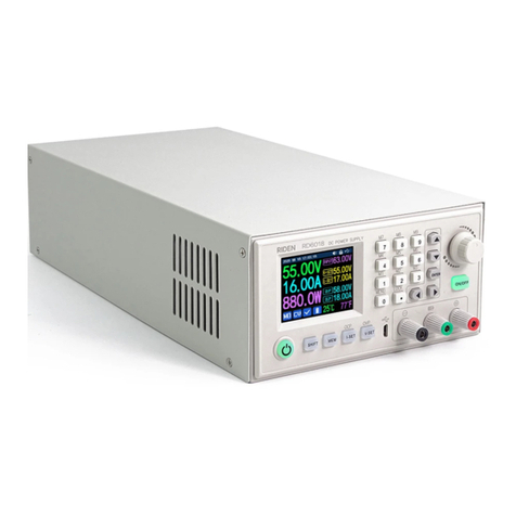
Riden RD6024 User manual

声明:本说明书著作权归杭州睿登科技有限公司所有,未经允许任何单位或个人不得用于商业用途。
38
Constant Voltage and Constant Current
DC Power Supply Instruction
Model: RD6024/RD6024-W
Date: 2022.1.7
Dear users, thank you for purchasing the constant voltage constant current DC
power supply produced by Hangzhou Ruideng Technology Co., Ltd. In order to let you
know more about the full function of this product, get a better experience and avoid
misuse. Please read this instruction carefully before using it. Keep it for future
reference.
Note: This instruction is corresponding to firmware V1.36, the page and
operation may be different under different firmware versions, please pay attention
when using it. We do recommend you to download the latest firmware for better
experience.

声明:本说明书著作权归杭州睿登科技有限公司所有,未经允许任何单位或个人不得用于商业用途。
39
CONSTANT VOLTAGE AND CONSTANT CURRENT............................................................................... 38
DC POWER SUPPLY INSTRUCTION ....................................................................................................38
1.1 TECHNICAL PARAMETER.................................................................................................................41
1.2 CORE FUNCTION ..........................................................................................................................42
1.3 PANEL INSTRUCTION .....................................................................................................................43
1.3.1 Front Panel ......................................................................................................................43
1.3.2 Back Panel .......................................................................................................................44
1.4 OPERATION INSTRUCTION ..............................................................................................................45
1.4.1 Main Page........................................................................................................................45
1.4.2 Operation Introduction ....................................................................................................47
ANDROID APP INSTRUCTION ...........................................................................................................54
2.1 MOBILE PHONE APP INSTALLATION..................................................................................................54
2.1.1 APP Download ................................................................................................................. 54
2.2 INSTALLATION INTRODUCTION .........................................................................................................54
2.2.1 APP Update...................................................................................................................... 54
2.2.2 APP Interface Display .......................................................................................................54
2.2.3 APP Operation .................................................................................................................55
IOS APP INSTRUCTION .....................................................................................................................59
3.1 MOBILE PHONE APP INSTALLATION..................................................................................................59
3.1.1 APP Download ................................................................................................................. 59
3.2 INSTALLATION AND OPERATION........................................................................................................59
3.2.1 APP Update...................................................................................................................... 60
3.2.2 UI Instruction ................................................................................................................... 60
3.2.3 APP Operation .................................................................................................................61
PC SOFTWARE INSTALLATION AND OPERATION INSTRUCTION ......................................................... 64
4.1 SOFTWARE DOWNLOAD ................................................................................................................64
4.1.1 Unzip Files .......................................................................................................................64
4.1.2 Unzip Files .......................................................................................................................64
4.2 SOFTWARE OPERATION .................................................................................................................65
4.2.1 Software Connection........................................................................................................65
4.2.2 PC Software Operation Instruction ...................................................................................66
4.3 FUNCTIONS INTRODUCTION ............................................................................................................66
4.3.1 Basic Functions ................................................................................................................ 67
4.3.2 Calibration .......................................................................................................................68
4.3.3 Advanced Function...........................................................................................................69

声明:本说明书著作权归杭州睿登科技有限公司所有,未经允许任何单位或个人不得用于商业用途。
40
4.3.4 RS485 Multiple Devices Communication...........................................................................69
4.3.5 Firmware Update .............................................................................................................70
4.3.6 Boot Logo Update ............................................................................................................ 71
4.3.7 Version Update Detection ................................................................................................72
4.3.8 Language Setting..............................................................................................................73
4.3.9 About ..............................................................................................................................73
APPENDIX ........................................................................................................................................75
APPENDIX 1: COMMON BATTERY VOLTAGE COMPARISON TABLE....................................................................75
APPENDIX 2: COMMON ELECTRIC CAR/BIKE BATTERY VOLTAGE COMPARISON CHART.........................................76

声明:本说明书著作权归杭州睿登科技有限公司所有,未经允许任何单位或个人不得用于商业用途。
41
1.1 Technical Parameter
Model
RD6024
RD6024-W
Input voltage range
6-70.00V
Output voltage range
0-60.00V
Output current range
0-24.00A
Output power range
0-1440W
Input voltage measurement resolution
0.01V
Output voltage setting measurement resolution
0.01V
Output current setting measurement resolution
0.01A
Battery voltage measurement resolution
0.01V
Input voltage measurement accuracy
±(1%+5 digits)
Output voltage accuracy between setting and
measurement
±(0.3%+3 digits)
Output current accuracy between setting and
measurement
±(0.5%+5 digits)
Battery voltage measurement accuracy
±(0.5%+3 digits)
Automatic cut off current value when charging
Set by yourself(higher than 100mA)
Output ripple typical
100mV@12A,150mV@24A VPP①
Working temperature range
-10℃~40℃
External sensor Temperature detection range:
-10℃~100℃/0℉~200℉
External sensor Temperature detection accuracy:
±3℃/±6℉
Constant voltage mode response time
2ms(0.1A-5A load)
Constant voltage mode load regulation
±(0.1%+2 digits)
Constant current mode load regulation
±(0.1%+3 digits)
Capacity measurement range
0-9999.99Ah
Energy measurement range
0-9999.99Wh
Constant voltage mode response time
±2%
Max output voltage
(input voltage÷1.1)-1②
Cooling fan start condition
Output current>8A or
System temperature>45℃

声明:本说明书著作权归杭州睿登科技有限公司所有,未经允许任何单位或个人不得用于商业用途。
42
Cooling fan shut down condition when working
Output current <7.9A and System temperature <45℃
Over temperature protection
System temperature >80℃
Screen brightness setting
0-5(6 level in total)
Screen
2.4 inch color HD display
Weight(with package)
About 0.72Kg
Product dimension
167*81*69mm
Support USB communication
Yes
Support WiFi communication
No
Yes
①:Ripple measurement method: noise and ripple are measured at X1 range, AC coupling,
20 MHz of bandwidth on your oscilloscope with a 0.1uF parallel capacitor a t the output terminals
②for example: input voltage is 24V,the max output voltage is 20.8V。
1.2 Core Function
Keypad + encoder potentiometer combination adjustment
·10 data groups for storage and call out
·2.4 inch HD color display
·Dedicated terminal for battery charging
·Firmware update, support more functions later
·Brand new PC software
·Support WiFi communication(RD6024-W) /USB communication
·Support Android/ IOS APP
·Support multiple display interfaces

声明:本说明书著作权归杭州睿登科技有限公司所有,未经允许任何单位或个人不得用于商业用途。
43
1.3 Panel Instruction
1.3.1 Front Panel
A: Power button
B: SHIFT Second function button
C: Quick storage button
D: Current/Over current protection setting
E: Voltage/Over voltage protection setting
F: Micro USB port
G: Power supply output negative terminal/
Battery charging negative terminal
H: Battery charging positive terminal
(Dedicated terminal for battery charging)
I: Power supply output positive terminal
J: Output switch
K: Enter/ Confirm button
L: encoder potentiometer/Cancel button
M: Direction button
N: keypad
O: Screen

声明:本说明书著作权归杭州睿登科技有限公司所有,未经允许任何单位或个人不得用于商业用途。
44
1.3.2 Back Panel
P: Input fuse
Q: Output fuse(only for under 10A short time usage)
R: Power source input interface
S: External temperature sensor interface
T: CR1220 battery socket
U: Communication module interface( wifi or RS485
board)
V: Fan interface(cannot add or replace other fan)
NOTE:
Power source input interface must be connected to 6-70V
constant DC power source. When the input voltage is greater than
72V, the output will be automatically turned off and an alarm (as
shown in the right picture) will be automatically prompt. When the
input voltage exceeds more, the product will be directly damaged
and cannot be repaired!
The external sensor cable (as shown on right) must be
connected to the external temperature sensor interface. The fan
interface cannot be connected to other fans. When the system
temperature is higher than 80℃, the output will be shut down and
show OTP on the screen. CR1220 is the clock battery (Please
prepare by yourself), it can power on the clock function.
Communication interface is a special interface, please don’t connect to other
modules or cables.
You can see the Wi-Fi module and RS-485 module in the picture below. If you
need RS-485 for industrial batch test and it is not on sale now, if you want to use that,
please contact us.

声明:本说明书著作权归杭州睿登科技有限公司所有,未经允许任何单位或个人不得用于商业用途。
45
1.4 Operation Instruction
After power-on, it will show boot image first, and then enters the main page.
1.4.1 Main Page
AA: Actual output voltage value
AB: Actual output current value
AC: Output power
AD: Current data group
AE: Constant voltage Constant
current status
AF: Protection status indication
AG: Battery charging indication
AH: Battery related information display area
AI: Over current protection value
AJ: Over voltage protection value
AK: Output current preset value
AL: Output voltage preset value
AM: Input voltage
AN: Communication interface
A O : Button lock status
AP: Button tune
AQ: Date time

声明:本说明书著作权归杭州睿登科技有限公司所有,未经允许任何单位或个人不得用于商业用途。
46
Traditional Style
Detail Style
Curve Style
At main page you can press button to change the display style between Traditional
Style, Detail Style and Curve Style, the display style will not be saved automatically, you need to
set default boot display at section 1.4.2.6 Main Page Style Setting.

声明:本说明书著作权归杭州睿登科技有限公司所有,未经允许任何单位或个人不得用于商业用途。
47
1.4.2 Operation Introduction
In the menu operation, the icon in red or cursor is the currently selected menu,
press to confirm or enter, press the encoder potentiometer to cancel or return,
press the direction button to move the cursor or switch menu, rotate the encoder
potentiometer to change the setting, the settings will be automatically saved when
returning from the menu page. Press and hold the 0 button and power on to restore
the factory settings, press and hold the 1 button and power on to restore the factory
calibration value, press and hold and power on to enter the boot mode.
1.4.2.1 Battery Charging Function Introduction
The device in the instruction video may not be RD6024, but the operation way of them are
similar.
Battery charging operation video:
https://www.youtube.com/watch?v=sOmKoUEmjdQ
After power on, at battery related information display area, external
temperature, capacity and energy will loop display. When the output is turned on:
capacity, energy will be automatically accumulated, and automatically cleared after
power off.
The green terminal is connected to the positive electrode of the battery, and the
black terminal is connected to the negative electrode of the battery. After the battery
is correctly connected, the battery charging indicator turns red and the battery is
connected. Press to start charging, the battery charging indicator turns green
. When the actual output current is lower than cut off current value (higher than
100 mA, can be set by user), or the temperature that the external temperature
sensor tested is greater than the cut off temperature value, the output will be cut off
automatically. Battery with protection board needs to be charged with red and black
terminals. The charging voltage and current should be set on your own.
It is strongly recommended to use the original charger to charge the battery. The
charging function of this machine can only serve as a temporary replacement, not for
long-term use. You need to know the battery parameter well so that you can use it to
charge, There is a risk of fire and explosion during the charging process if you use the
wrong way to charge. Common Battery voltage

声明:本说明书著作权归杭州睿登科技有限公司所有,未经允许任何单位或个人不得用于商业用途。
48
1.4.2.2 Main Page Output Voltage and Current Setting
Output voltage and current setting operation video:
https://www.youtube.com/watch?v=KPnXiwCGSFg
Press button to set the output current value,
you can use encoder potentiometer to adjust the
output value directly. And you will not set the value
which exceeds the limit in this way, press
button to move the cursor. Of course you can use
keypad to type in the value, and press to
confirm, and it will save the set value and set current
range, if you set a value exceeds the limit, it will
prompt like what shows in Figure 1. If you set the wrong value, you can press
encoder potentiometer to cancel.
Press button to set the output voltage value, the operation way is similar
to output current setting.
Press + button / + button to set the over current
protection/ over voltage protection value. The operation method is similar to output
current setting. If you want to set the over current auto cut off function, your OCP
value should be higher than the Current setting value.
When the device is under constant voltage mode, it will show , and it will
show when under constant current mode; when the device works normally it
will show at protection status indication, when the actual output current value
is higher than the over current protection value(OCP), the output will be cut off
automatically, and show , when the actual output voltage value is higher than
the over voltage protection value(OVP), the output will be cut off automatically, and
show , when the system temperature is higher than 80℃, the output will be cut
off automatically, and show .
1.4.2.3 Data Group Quick Storage and Call out
Data group quick store and call out operation video:
https://www.youtube.com/watch?v=Y4ywGSxDy0M
Press + keypad button 1-9, you can store the output voltage value, output
current value, over voltage protection value, over current protection value into the
corresponding data group(as shown in figure 2).
Figure 1

声明:本说明书著作权归杭州睿登科技有限公司所有,未经允许任何单位或个人不得用于商业用途。
49
then press to confirm, it will show at
bottom left, you can press button and choose
“X”, then press ENTER to cancel, after change the
setting value it will show .
Press + keypad button 1-9 to quick call out
the saved data (as shown above in figure 3) from the
corresponding data group. Press to confirm, It
will show ,
after change the setting value it will show . When
disable the “Take OK” option, it will be called out
directly to change the data setting value, no prompt.
is the default data group, when you edit the
settings and press button or rotate encoder
potentiometer to change the setting and press
encoder potentiometer to return, it will be stored into automatically, or you go
to the data group setting menu, change the setting and press encoder potentiometer
to return, it will save too, and it will not save by other settings.
1.4.2.4 Keypad lock and unlock
Keypad lock operation video:
https://www.youtube.com/watch?v=UYMcgywKB1Q
Press +to lock or unlock the keyboard.
And the keypad will be automatically locked when
communication starts, there will be displayed on
the top (cannot unlock manually), at this time, the
power button can be used, pressing other button will
show(as shown in figure 4), the keypad will be
automatically unlocked after 3 seconds when the connection disconnected, there will
be displayed.
1.4.2.5 System Setting
System setting operation video:
figure 2
figure 3
figure 4

声明:本说明书著作权归杭州睿登科技有限公司所有,未经允许任何单位或个人不得用于商业用途。
50
https://www.youtube.com/watch?v=ml15mX4u5bE
Press + to enter the system setting menu, the icon in Red shows the
menu being chosen, press or to enter the sub-menu, the option in blue
is the option being chosen, you can rotate the encoder potentiometer to change
setting, and you can press button to select menu.
Press + to enter the system setting menu showed in figure 5, press
or to enter the sub-menu.
Settings Sub-menu:
System language is is set to English by default.
You can also set Simplified Chinese, French, Germany
and Russian language;
Take OK i s set to ON by default, when you
quickly call out a data group, there will be a prompt
to let you confirm, if you set OFF for this option, the
settings will be edited directly when call out a data group;
Take Out is set to OFF by default, when call out a data group, it will keep the
previous output status, when set it ON, it will output directly when call out a data
group.
Boot Power is set to OFF by default, when boot the device the output is cut off,
when set it on, it will automatically turn on the output after booting.
Boot Logo is set to ON by default, when boot the device, it will show the boot
logo first, then enter the main interface, when set it OFF, it will enter the main
interface directly.
Buzzer is set to ON by default,it will show on the top, and you can hear the
beep when press the button. When set it OFF, it will show , there will not be beep
when press the button.
Backlight is set to level 4 by default, it can be set between level 0-5.
Update Rate is set to Low by default, you can set it low/mid/high, it is the fresh
rate of the real output voltage and current.
Max Power is set to 1440W by default, you can set it between 0-1440W, it is the
max output power. On the top you can see the *1 icon, it is the adjustment
magnification, you can press or to choose the different magnification so that
you can set the value quickly, The max output is default voltage priority mode, when
the setting voltage*setting current is higher than the max power, the device will
automatically
figure 5

声明:本说明书著作权归杭州睿登科技有限公司所有,未经允许任何单位或个人不得用于商业用途。
51
decrease the output current setting value. When used together with low power
power source, it is recommended to set the value as
the rated power of the power source*95%;
Temperature unit is ℃by default, it can be
switched between ℃and ℉(figure 6);
Battery Charger Sub-menu(figure 7):
CutOff Current is set to 100mA by default and it
can be edited(at least 100 mA). On the top you can see
the *1 icon, it is the adjustment magnification, you can
press or to choose the different magnification
so that you can set the value quickly, when the real
output current is lower than this set value, the output
will be cut off automatically.
Cut-Off Temp. is set to 60℃by default, when the
external temperature sensor detect over 60℃, the
output will be cut off automatically.
Communication Sub-menu(figure 8):
Interface is set to USB by default, you can also set
it to WIFI/TTL/RS485, USB means the micro USB port,
you can see on the top when set it USB, and
when the communication starts, it will show ; You
need to insert a WIFI board to use the WIFI function,
and it will show on the top, and when the
communication starts, it will show ; TTL is not
available now; You need to insert RS485 module to use
RS485, and it will show on the top, and when the
communication starts, it will show .
Address is set to 001 by default, you can set it between 001 and 255;
The Baud rate and address on the device should be same with the information
on PC software or APP. You can see more communication at PC software and APP
section.
Date and Time Sub-Menu(figure 9):
Date and Time can be set from Year 2000 to 2100, press or you can
select the option, and use encoder potentiometer can adjust the value, it will be
applied immediately when you change the value, please do not set the wrong time.
figure 6
figure 7
figure 8

声明:本说明书著作权归杭州睿登科技有限公司所有,未经允许任何单位或个人不得用于商业用途。
52
1.4.2.6 Main Page Display Style Setting
Main interface display style setting operation
video:
https://drive.google.com/drive/folders/1gMkuCZr
r_G-PlyHqO-i6fxdS-XRvuOIG?usp=sharing
You can press + to enter the system
setting menu, then press and it will be switched
to display style menu(as shown in figure 10): you can
press or to enter the sub-menu.
Layout Sub-menu:
Digits Style is set to Normal by default, you can
set it to Normal/7-Seg V1/7-Seg V2(as shown in figure
11).
Home Style is set to 0(traditional style), you can
also set it to 1(Detail Style) or 2(Curve Style), the
display style you choose will become the default style
after power on.
Custom Colors(figure 12):
You can set the the display colors for output
voltage, output current, output power.....as shown in
figure 10 and figure 11. After change the color, you
need to turn on the Custom Colors option to apply the
settings(as shown in figure 13).
1.4.2.7 Storage Data Setting
Data group setting in manual operation video:
https://www.youtube.com/watch?v=0sJlwSGW_oc
You can press + to enter the system
setting menu, and then press button twice to
enter the data storage setting menu(as shown in figure
14).
Press button to set the output current value,
you can use encoder potentiometer to adjust the
output value directly. And you will not set the value
which exceeds the limit in this way, press
button to move the cursor. Of course you can use keypad to type in the value, and
figure 9
figure 10
figure 11
figure 12
figure 13

声明:本说明书著作权归杭州睿登科技有限公司所有,未经允许任何单位或个人不得用于商业用途。
53
press to confirm, and it will save the set value and set current range, if you set
a value exceeds the limit, it will prompt like what shows in Figure 1. If you set the
wrong value, you can press encoder potentiometer to
cancel.
Press button to set the output voltage
value, the operation way is similar to output current
setting.
Press + button / + button to
set the over current protection/ over voltage
protection value. The operation method is similar to
output current setting.
After setting, press the encoder potentiometer to return and save setting.
1.4.2.8 System Information
System information operation video:
https://www.youtube.com/watch?v=PN8tBhezmtA
You can press + to enter the system setting menu, and then press
button 3 times to enter the system information menu(as shown in figure 15).
Product Model is the device name, Product SN is product serial number,
Firmware is the firmware version, Temperature is the System temperature.
figure 14
figure 15

声明:本说明书著作权归杭州睿登科技有限公司所有,未经允许任何单位或个人不得用于商业用途。
54
Android APP Instruction
2.1 Mobile Phone APP Installation
Only RD6024-W supports WIFI connection. This App only supports Android 5.0
to Android 10.0 operating system, and there may be incompatibilities problems
between APP and operating system, please install and test the software before
buying the product. It will apply for location service, please agree and turn on the
location service. After downloading the mobile APP zip-file, please install the APP
from file manager. Don’t install or remove Wi-Fi module when the device is powered
on, otherwise it will be damaged. This instruction is made for version 1.0.11, there
will be little difference between different versions, and we do recommend you to
download the latest APP for better experience.
2.1.1 APP Download
You can download the APP in Google Play by searching “RD Power”.
You can also download the RD6024APP zip-file in this URL:
https://drive.google.com/drive/folders/1jwAnxKiQZKkxMWpQnv4rrPw2KQk9uY-z?us
p=sharing
If you cannot find the app in both ways, contact the seller to get it.
2.2 Installation Introduction
Android APP download and connection video instruction:
https://www.youtube.com/watch?v=BnC9mJ1zevg
2.2.1 APP Update
Click the APP icon, After the APP starts, it will automatically detect whether
there is a new version, and it will remind you by popping the window. You need to
check if there is a new version by manual detecting. If you download the APP from
Google Play, you need to detect new version by yourself.
2.2.2 APP Interface Display
When finish the installation and succeed in connection, it will show the main page as shown
in the picture below.

声明:本说明书著作权归杭州睿登科技有限公司所有,未经允许任何单位或个人不得用于商业用途。
55
BA: sidebar
BP: adjust wheel
BB: add device
BQ: move the cursor to the left
BC: return
BR: move the cursor to the right
BD: more options
BS: set button
BE: curve
BT: screen brightness
BF: actual output voltage
BU: system temperature
BG: actual output current
BV: sync time
BH: actual output power
BW: data group quick call out
BI:input voltage
BX: battery voltage
BJ: preset voltage value
BY: external sensor temperature detecting value
BK: preset current value
BZ: accumulated output capacity
BL: ON/OFF button
CA: accumulated output energy
BM: protection status indication
CB: device name
BN: keypad lock indication
CC: SN number
BO: constant voltage/current status indicator
CD: product firmware version
2.2.3 APP Operation
2.2.3.1 Network Distribution
Connect Wi-Fi for the first time, please
insert the WiFi board to the right position, then
power on RD6024, you will see the blue LED
blinks once. Set the communication interface to
WIFI, restart RD6024, then place the RD6024
and the mobile phone close to the 2.4G router
(the mobile phone must also be under the same
2.4G network, and the router must disable the AP isolation function and the WMM
figure 16

声明:本说明书著作权归杭州睿登科技有限公司所有,未经允许任何单位或个人不得用于商业用途。
56
function).
RD6024 will wait for the phone to connect as shown in Picture 16. Press “BA”
(add device) and choose “RD power series”, it will show like Picture 17, then enter
the WiFi password and confirm you are using 2.4G network as shown in Picture 18.
Press “INITIALIZATION”and wait 10 seconds
figure 17
figure 18
RD6024 will obtain the IP address of your
phone(figure 19), if it shows right, confirm that
“device display sever IP”, and click “Confirm”, wait 20s
(figure 20),APP show connection successful, RD6024
will start automatically, the network distribution
success, return to the main page and click the
connect in the “BD”.
Figure 19
This manual suits for next models
1
Table of contents
Other Riden Power Supply manuals