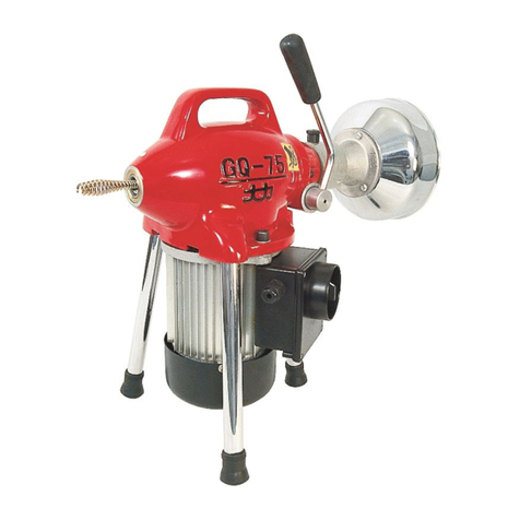
Ridgid Kollmann K-375R User manual

Kollmann
1/2″Cage Machine
OPERATOR’S
MANUAL
• Pour français voire page 13
• Para el castellano vea la
paginá 27
K-375R
WARNING!
Read this Operator’s Manual
carefully before using this
tool. Failure to understand
and follow the contents of
this manual may result in
electrical shock, fire and/or
serious personal injury.

Table of Contents
Recording Form for Machine Model and Serial Number............................................................................................1
General Safety
Work Area Safety........................................................................................................................................................2
Electrical Safety...........................................................................................................................................................2
Personal Safety...........................................................................................................................................................2
Tool Use and Care......................................................................................................................................................3
Service ........................................................................................................................................................................3
Specific Safety Information
Drain Cleaner Safety...................................................................................................................................................3
Description, Specifications and Standard Equipment
Description ..................................................................................................................................................................4
Specifications..............................................................................................................................................................4
Standard Equipment....................................................................................................................................................4
Machine Assembly
Instructions for Mounting Drum...................................................................................................................................5
Instructions for Mounting Belt Guard...........................................................................................................................5
Machine Inspection .......................................................................................................................................................5
Machine Set Up..............................................................................................................................................................6
Operating Instructions..................................................................................................................................................7
Special Procedures
Reverse Operating Instructions...................................................................................................................................8
Drum Removal ............................................................................................................................................................8
Installing Replacement Cable......................................................................................................................................9
Accessories....................................................................................................................................................................9
Maintenance Instructions
Lubrication...................................................................................................................................................................9
Cables.........................................................................................................................................................................9
Machine Storage..........................................................................................................................................................10
Service and Repair ......................................................................................................................................................10
Trouble Shooting.........................................................................................................................................................11
Wiring Diagram............................................................................................................................................................11
Lifetime Warranty..........................................................................................................................................Back Cover
Ridge Tool Companyii
K-375R 1/2″Cage Machine
Kollmann

K-375R 1/2″Cage Machine
Record Serial Number below and retain product serial number which is located on nameplate.
Serial
No.
K-375R
1/2″Cage Machine
Kollmann

Kollmann
K-375R 1/2″Cage Machine
Ridge Tool Company2
General Safety Information
WARNING! Read and understand all instructions. Failure
to follow all instructions listed below may
result in electric shock, fire, and/or serious
personal injury.
SAVE THESE INSTRUCTIONS!
Work Area Safety
•Keep your work area clean and well lit. Cluttered
benches and dark areas invite accidents.
•Do not operate tools in explosive atmospheres,
such as in the presence of flammable liquids,
gases or dust. Tools create sparks which may ignite
the dust or fumes.
•Keep by-standers, children and visitors away while
operating a tool. Distractions can cause you to lose
control.
Electrical Safety
•Grounded tools must be plugged into an outlet,
properly installed and grounded in accordance
with all codes and ordinances. Never remove the
grounding prong or modify the plug in any way. Do
not use any adapter plugs. Check with a quali-
fied electrician if you are in doubt as to whether
the outlet is properly grounded. If the tools should
electrically malfunction or break down, grounding pro-
vides a low resistance path to carry electricity away
from the user.
•Avoid body contact with grounded surfaces such
as pipes, radiators, ranges and refrigerators. There
is an increased risk of electrical shock if your body is
grounded.
•Do not expose electrical tools to rain or wet con-
ditions. Water entering a tool will increase the risk of
electrical shock.
•Do not abuse cord. Never use the cord to carry the
tools or pull the plug from an outlet. Keep cord
away from heat, oil, sharp edges or moving parts.
Replace damaged cords immediately. Damaged
cords increase the risk of electrical shock.
•When operating a tool outside, use an outdoor
extension cord marked “W-A” or “W”. These cords
are rated for outdoor use and reduce the risk of elec-
trical shock.
•Use only three-wire extension cords which have
three-prong grounding plugs and three-pole recep-
tacles which accept the tool’s plug. Use of other
extension cords will not ground the tool and increase
the risk of electrical shock.
•Use proper extension cords. (See chart.) Insufficient
conductor size will cause excessive voltage drop, loss
of power.
•Before using, test the Ground Fault Circuit Inter-
rupter (GFCI) provided with the power cord to
insure it is operating correctly. GFCI reduces the risk
of electrical shock.
•Extension cords are not recommended unless they
are plugged into a Ground Fault Circuit Interrupter
(GFCI) found in circuit boxes or outlet receptacles.
The GFCI on the machine power cord will not prevent
electrical shock from the extension cords.
•Keep all electric connections dry and off the
ground. Do not touch plugs or tool with wet hands.
Reduces the risk of electrical shock.
Personal Safety
•Stay alert, watch what you are doing and use com-
mon sense when operating a power tool. Do not
use tool while tired or under the influence of drugs,
alcohol, or medications. A moment of inattention
while operating power tools may result in serious per-
sonal injury.
•Dress properly. Do not wear loose clothing or
jewelry. Contain long hair. Keep your hair, cloth-
ing, and gloves away from moving parts. Loose
clothes, jewelry, or long hair can be caught in moving
parts.
•Avoid accidental starting. Be sure switch is OFF
before plugging in. Carrying tools with your finger
on the switch or plugging tools in that have the switch
ON invites accidents.
Minimum Wire Gauge for Cord Set
Nameplate
Amps Total Length (in feet)
0 – 25 26 – 50 51 – 100
0 – 6 18 AWG 16 AWG 16 AWG
6 – 10 18 AWG 16 AWG 14 AWG
10 – 12 16 AWG 16 AWG 14 AWG
12 – 16 14 AWG 12 AWG NOT RECOMMENDED
Grounding pin
Cover of
grounded
outlet box
Grounding pin

K-375R 1/2″Cage Machine
Kollmann
Ridge Tool Company 3
•Remove adjusting keys or switches before turning
the tool ON. A wrench or a key that is left attached to
a rotating part of the tool may result in personal injury.
•Do not over-reach. Keep proper footing and bal-
ance at all times. Proper footing and balance enables
better control of the tool in unexpected situations.
•Use safety equipment. Always wear eye protection.
Dust mask, non-skid safety shoes, hard hat, or hearing
protection must be used for appropriate conditions.
Tool Use and Care
•Use clamp or other practical way to secure and
support the workpiece to a stable platform. Holding
the work by hand or against your body is unstable
and may lead to loss of control.
•Do not force tool. Use the correct tool for your
application. The correct tool will do the job better
and safer at the same rate for which it is designed.
•Do not use tool if switch does not turn it ON or
OFF. Any tool that cannot be controlled with the switch
is dangerous and must be repaired.
•Disconnect the plug from the power source before
making any adjustments, changing accessories, or
storing the tool. Such preventive safety measures
reduce the risk of starting the tool accidentally.
•Store idle tools out of the reach of children and
other untrained persons. Tools are dangerous in
the hands of untrained users.
•Maintain tools with care. Keep cutting tools sharp
and clean. Properly maintained tools with sharp cut-
ting edges are less likely to bind and are easier to
control.
•Check for misalignment or binding of moving
parts, breakage of parts, and any other condi-
tion that may affect the tool's operation. If dam-
aged, have the tool serviced before using. Many
accidents are caused by poorly maintained tools.
•Use only accessories that are recommended by the
manufacturer for your model. Accessories that may
be suitable for one tool may become hazardous when
used on another tool.
•Keep handles dry and clean; free from oil and
grease. Allows for better control of the tool.
Service
•Tool service must be performed only by qualified
repair personnel. Service or maintenance performed
by unqualified repair personnel could result in injury.
•When servicing a tool, use only identical replace-
ment parts. Follow instructions in the Maintenance
Section of this manual. Use of unauthorized parts or
failure to follow maintenance instructions may create a
risk of electrical shock or injury.
Specific Safety Information
WARNING
Read this operator’s manual carefully before using
the K-375R Drain Cleaner. Failure to understand
and follow the contents of this manual may result in
electrical shock, fire and/or serious personal injury.
Call the Ridge Tool Company, Technical Service
Department at (800) 519-3456 if you have any questions.
Drain Cleaner Safety
1. Wear gloves provided with the machine. Never
grasp a rotating cable with a rag or loose fitting
cloth glove. Could become wrapped around the
cable and cause serious injury.
2. Never operate machine with belt guard removed.
Fingers can be caught between the belt and pulley.
3. Do not overstress cables. Keep two hands on
the cable for control when machine is running.
Overstressing cables because of obstruction may
cause twisting, kinking or breaking of the cable and
result in serious injury.
4. Position machine within two feet of inlet. Greater
distances can result in cable twisting or kinking.
5. Machine is designed for one person operation.
Operator must control foot switch and cable.
6. Use foot switch to operate machine while main-
taining good footing and balance. Do not operate
machine in (REV) reverse. Operating machine in
reverse can result in cable damage and is used only
to back tool out of an obstruction.
7. Keep hands away from rotating drum and guide
tube. Do not reach into drum unless machine is
unplugged. Hand may be caught in the moving parts
resulting in serious injury.
8. Do not use this machine in drains where cleaning
compounds have been used. Serious burns can
result from some drain cleaning compounds. Drain
should be cleaned by a drain cleaning professional.
9. Do not operate machine if operator or machine is
standing in water. Will increase the risk of electrical
shock.


Kollmann
K-375R 1/2″Cage Machine
Ridge Tool Company4
• T-202 Bulb Auger (Figure 2)
• T-211 Spade Cutter (Figure 3)
• T-205 “C” Cutter (Figure 4)
• Safety & Instruction Card
• Rental Checklist Card
• Instruction Video
Figure 1 –Machine with Gloves, Cable and Coupling Pin
Key
Figure 2 –T-202 Bulb Auger: Used for exploring and
breaking up stoppages or returning samples
to surface to determine correct tool.
Figure 3 –T-211 Spade Cutter: Used to get soft grease
or debris moving in the drain.
10. Wear safety glasses and rubber soled, non-slip
shoes. Use of this safety equipment may prevent
serious injury.
11. Only use the K-375R to clean drain lines 2″to 4″in
diameter. Follow instructions on the use of the
machine. Other uses or modifying the drain cleaner
for other applications may increase the risk of injury.
Description, Specifications and
Standard Equipment
Description
The RIDGID/Kollmann K-375R Drain Cleaning Machine
will clean drain lines 2″to 4″in diameter and 50 feet in
length. It is specifically designed for the rental market
with a steel wire drum to allow for inspection and cleaning
of the cable.
The steel wire drum is belt-driven by a 1/3HP electric
motor that has a grounded electrical system. An inte-
gral Ground Fault Interrupter (GFCI) is built into the line
cord and a pneumatic foot actuator provides On/Off con-
trol of the motor.
The drum powers a 1/2″integral wound solid core cable that
has a quick change coupling system for connecting or dis-
connecting tools. The cable is manually fed in and out of the
drain. An integral torque limiter will cause the drum to stop
rotating when excessive torque is created as the cutting tool
attached to the cable hits a snag and stops rotating.
Specifications
Line Capacity................Recommended for indoor drain
lines: 2″- 4″lines through 50′
Drum Capacity.............50′of 1/2″cable
Motor Type...................115V/60 Hz, Reversible,
Split Phase
Rating ..........................1/3HP @ 1725 RPM
Amps............................6.7
Weight
(Machine & Cable).......73 lbs.
Length..........................22″
Width............................13″
Standard Equipment
K-375R
• K-375R Drum Machine (Figure 1)
• C-44 IW Cable w/solid core (1/2″x 50′)
• 1 Pair Gloves
• A-13 Coupling Pin Key

K-375R 1/2″Cage Machine
Kollmann
Ridge Tool Company 5
Figure 4 –T-205 “C”Cutter: Used for general cleaning
to remove materials clinging to pipe walls.
Machine Assembly
WARNING
To prevent serious injury, proper assembly of the
Drain Cleaner is required. The following proce-
dures should be followed:
Instructions For Mounting Drum
1. Align bearing bore in back of drum with shaft. Let
drum slide down shaft so that the locking mecha-
nism catches. In locked position, drum will rotate
freely but should not slide forward without pulling the
release pin.
2. Engage V-belt drive with drum. Push down on top of
motor so that you depress the two large springs
underneath the motor table and slip belt over drum
(Figure 5).
NOTE! Make sure belt properly contacts drive pulley
before slipping over drum.
Figure 5 –Push down on motor, slip belt over drum.
Instructions For Mounting Belt Guard
Fasten guard to motor using the two (2) wing nuts. Adjust
guard so that it is approximately 1/4″from drum (Figure 6).
Gap between belt guard and drum should
not exceed 1/2″to prevent fingers being caught between
belt and pulley. Do not operate this machine without a
belt guard.
Machine Inspection
1. Make sure the Drain Cleaning Machine is unplugged
and the directional switch is set to the OFF position
(Figure 6).
2. Make sure the foot switch is present and attached to
the Drain Cleaning Machine (Figure 6). Do not oper-
ate the machine without a foot switch.
3. Inspect the power cord, Ground Fault Circuit
Interrupter (GFCI) and plug for damage. If the plug
has been modified, is missing the grounding prong or
if the cord is damaged, do not use the Drain Cleaning
Machine until the cord has been replaced.
Figure 6 –K-375R Drain Cleaner
4. Inspect the Drain Cleaning Machine for any broken,
WARNING
To prevent serious injury, inspect your Drain
Cleaning Machine. The following inspection pro-
cedures should be performed before each use.
WARNING
Belt Guard
GFCI and Plug Foot Switch
Electrical Switch

K-375R 1/2″Cage Machine
Kollmann
Ridge Tool Company6
missing, misaligned or binding parts as well as any
other conditions which may affect the safe and normal
operation of the machine. If any of these conditions
are present, do not use the Drain Cleaning Machine
until any problem has been repaired.
5. Lubricate the Drain Cleaning Machine, if necessary,
according to the Maintenance Instructions.
6. Use tools and accessories that are designed for your
drain cleaner and meet the needs of your application.
The correct tools and accessories allow you to do the
job successfully and safely. Accessories suitable for
use with other equipment may be hazardous when
used with this drain cleaner.
7. Clean any oil, grease or dirt from all equipment han-
dles and controls. This reduces the risk of injury due
to a tool or control slipping from your grip.
8. Inspect the cutting edges of your tools. If necessary,
have them sharpened or replaced prior to using the
Drain Cleaning Machine. Dull or damaged cutting
tools can lead to binding and cable breakage.
9. Inspect cables and couplings for wear and damage.
Cables should be replaced when they become
severely worn or corroded. A worn cable can be
identified when the outside coils become flat.
Worn or damaged cables can break caus-
ing serious injury.
Machine Set-Up
1. Check work area for:
• Adequate lighting
• Grounded electrical outlet
• Clear path to the electrical outlet that does not con-
tain any sources of heat or oil, sharp edges or
moving parts that may damage electrical cord.
• Dry place for machine and operator. Do not use the
machine while standing in water.
• Flammable liquids, vapors or dust that may ignite.
2. Position the Drain Cleaning Machine within 2′of
sewer inlet. Greater distance can result in cable twist-
ing or kinking.
3. Position the air foot switch pedal for easy operator
accessibility. Machine is designed for one person
operation.
4. Make sure FOR/OFF/REV switch is in the OFF position.
5. Select and install the proper tool to the end of the
cable. The T-Slot Coupler allows the tool to be
snapped into the cable coupler (Figure 7). To remove
tool, use the pin key to depress the plunger and slide
the coupling apart.
Figure 7 –Coupling and Uncoupling Tools
NOTE! Proper Tool Selection
The tools provided with this drain cleaner along with a
description of their intended use are shown in Figures 2,
3 and 4. A good rule of thumb is to use a tool at least 1″
smaller than the line to be cleaned. The style of the
tool is determined by the nature of the job and is left up
to the operator.
6. Plug the Drain Cleaning Machine into the electrical
outlet, making sure to position the power cord along
the clear path selected earlier. If the power cord does
not reach the outlet, use an extension cord in good
condition.
To avoid electric shock and electrical fires,
never use an extension cord that is damaged or does not
meet the following requirements:
• The cord has a three-prong plug similar to shown in
Electrical Safety section.
• The cord is rated as “W” or “W-A” if being used out-
doors.
• The cord has sufficient wire thickness (16 AWG
below 50′/14 AWG 50′- 100′). If the wire thickness is
too small, the cord may overheat, melting the cord’s
insulation or causing nearby objects to ignite.
To Couple Cable
and Tools
Snap Together Insert Pin Slide Apart
To Uncouple Cable and Tools
WARNING
To prevent serious injury, proper set-up of the machine
and work area is required. The following procedures
should be followed to set-up the machine:
WARNING
WARNING

K-375R 1/2″Cage Machine
Kollmann
Ridge Tool Company 7
To reduce risk of electrical shock, keep all
electrical connections dry and off the ground. Do not
touch plug with wet hands. Test the Ground Fault Circuit
Interrupter (GFCI) provided with the electric cord to insure
it is operating correctly. When test button is pushed in, the
indicator light should go off. Reactivate by pushing the
reset button in. If indicator light goes on, the machine is
ready to use. If the GFCI does not function correctly, do
not use the machine.
Operating Instructions
Always assume the correct operating pos-
ture in order to maintain proper balance (Figure 8). Should
an unexpected situation arise, this posture provides you
with the opportunity to safely keep control of the machine
and cable.
• Be sure you can quickly remove your foot from the
foot switch.
• Hand must be on the cable to control its twisting
action when it hits an obstruction.
• Keep hands away from rotating drum. Do not reach
into drum unless machine is unplugged.
Figure 8 –Proper Operating Position
1. Pull sufficient cable out of the drum to start tool and
cable into the sewer inlet. Push cable into inlet as far
as it will go.
2. Move FOR/OFF/REV switch into FOR (forward) posi-
tion. Grasp cable with two gloved hands and pull
approximately 1 foot of additional cable out of
machine, building a slight loop of cable between
machine and sewer inlet (Figure 8).
WARNING
Before starting machine, both operator’s gloved
hands must be on the cable.
3. While depressing foot switch to start machine, use
both gloved hands to grasp and push cable into
sewer inlet. Rotating cable will slowly work its way into
line as operator applies downward pressure with
gloved hands on cable loop.
4. Continue to feed the cable into the line until resistance
or obstruction is encountered. This will become appar-
ent to operator as it will be difficult to feed additional
cable into line and/or the cable will have a tendency to
twist sideways in operator’s hands.
5. If cable loads down in the obstruction, relieve load by
pulling back on cable with short, quick jerks to free cut-
ter. Slowly advance cable back into the obstruction.
Repeat this process until the obstruction is clear.
Remember, make sure the cutter is rotating at all
times and never force the cable. If motor turns but the
drum stops, the torque limiter is slipping because of
excessive force.
WARNING
Wear gloves provided with machine. Never grasp a
rotating cable with a rag or loose fitting cloth
glove that may become wrapped around the cable
causing serious injury.
Always wear eye protection to protect your eyes
against dirt and other foreign objects. Wear rubber
soled, non-slip shoes.
Do not operate this machine in drains containing
drain cleaning compounds. Recommend calling a
drain cleaning professional.
WARNING
WARNING

K-375R 1/2″Cage Machine
Kollmann
Ridge Tool Company8
WARNING
Do not allow tension to build up in the cable. This
will happen if the cutting tool hits a snag and
stops turning, but the motor and its drum continue
to rotate. Torque builds until the cable suddenly
twists, potentially wrapping around your hand or
arm. This can happen quickly and without warning,
so proceed slowly and carefully as you feed the
cable into the drain. If tool gets hung up in an
obstruction, refer to Reverse Operating Instructions
in the “Special Procedures” section.
6. Once obstruction is cleared, it is recommended that
operator flush debris from line with running water.
Repeat Step 5 several times if necessary for thorough
cleaning job and then work cable through additional
stoppages as required.
7. To retrieve cable from drain line, release foot actuator
and allow machine to come to a complete stop. Pull
one to two feet of cable from sewer and manually
push back into the machine. This procedure should be
continued until it is apparent that tool is just inside
sewer inlet.
Never retract tool from sewer inlet while
cable is rotating. Tool can whip causing serious injury.
NOTE! It is recommended that a continuous flush of
water be used to clean the cable and tool as
they are retrieved.
8. Turn FOR/OFF/REV switch to OFF position and
remove cord from power source.
9. Pull remaining cable and tool from sewer and hand
feed cable back into machine.
Special Procedures
Reverse Operating Instructions
Use REVERSE only to free a tool caught in an obstruc-
tion. If this should occur, immediately remove foot from
foot switch and allow machine to come to a full and
complete stop. Tighten screw on nose of machine so that
it firmly captures cable to avoid kinks occurring inside the
drum. Place FOR/OFF/REV switch to REV (Reverse)
position. Grasp cable with gloved hands and pull while
tapping foot switch. When tool is dislodged, place
FOR/OFF/REV switch to FOR (Forward) position, loosen
set screw on nose of machine and follow normal oper-
ating procedures.
Never operate this machine in REV
(reverse) for any other purpose. Operating in reserve can
damage a cable and cause serious injury.
Drum Removal
WARNING
FOR/OFF/REV switch should be OFF and machine
unplugged before removing or installing drum.
1. Disengage the V-belt drive from the drum (Figures 9
and 10).
2. Rotate the drum so that the release pin is in the 12
o’clock position and is easily accessible (Figure 11).
Figure 11 –Rotate drum so release pin is easily accessible.
Figure 12 –Lift release pin UPWARD to release drum
lock mechanism.
Figure 10 –With belt tension
released, slip belt off drum
Figure 9 –Push down on
motor to release spring ten-
sion on belt
WARNING
WARNING

2. Reach inside the drum and maneuver cable so that it
is under the cable bracket.
3. Retighten the screw to clamp the cable against the
back wall of the drum.
4. Mount the drum on the machine and, leaving the V-
belt disengaged, push the cable into the drum. The
guide tube will spin freely to evenly distribute the
cable around the drum.
Accessories
Only the following RIDGID/Kollmann prod-
ucts have been designed to function with the K-375R
Drain Cleaning Machine. Other accessories suitable for
use with other tools may become hazardous when used on
the K-375R. To prevent serious injury, use only the acces-
sories listed below.
Maintenance Instructions
WARNING
Make sure machine is unplugged from power
source before performing maintenance or making
any adjustment.
Lubrication
Grease all exposed, moving and rotating parts, such
as guide tube assembly, as required.
NOTE! No lubrication of the Motor Shaft is required.
Cables
Cables should be thoroughly flushed with water to pre-
vent damaging effects of sediment and drain cleaning
compounds. Periodically lubricate cables and couplings
with RIDGID/Kollmann Cable Rust Inhibitor. See acces-
sories for catalog numbers.
When not in use, store cables indoors to prevent deteri-
oration by the elements.
K-375R 1/2″Cage Machine
Kollmann
Ridge Tool Company 9
3. Hook finger under release pin and lift upward to
release the drum lock mechanism (Figure 12). With
the other hand grasp the drum by one of the hand
holes on front.
4. While holding the release pin in the unlocked position,
pull the drum forward. Drum should slide freely on
shaft. Grasp drum with both hands and slide it off
shaft.
Installing Replacement Cable
To Remove Damaged or Worn Cable
1. Remove drum from machine (as outlined above).
2. Pull out excess cable from drum allowing access to
cable bracket.
3. Loosen screw on back of drum that fastens cable
bracket clamping cable against back wall of drum.
4. Pull end of old cable from drum and discard.
To Install Replacement Cable
NOTE! To make cable installation easier, completely
uncoil new cable before proceeding. Also, a 30°
bend about 4 inches from back end of cable
will facilitate it entering the drum.
1. Insert about 24 inches of cable through the guide
tube into the drum.
IMPORTANT: Cable should coil into the drum in a
counter-clockwise direction (Figure 13).
Figure 13 –Coil cable into drum as shown.
Catalog Model
No. No. Description
87592 C-44 IW 1/2″x 50′Solid Core Cable
62995 T-202 Bulb Auger, 11/8″
63035 T-211 Spade Cutter, 13/8″
54842 T-205 “C” Cutter
59230 A-13 Pin Key
41937 — Gloves
37787 A-375 Plastic Drum Assembly
59782 — Two-Wheel Transport Cart
59982 — Cable Rust Inhibitor, 1 Quart
29987 — Cable Rust Inhibitor, 1 Gallon
WARNING

Service and Repair
Service and repair work on this Drain Cleaner must be
performed by qualified repair personnel. Machine should
be taken to a RIDGID Independent Authorized Service
Center or returned to the factory. All repairs made by
Ridge service facilities are warranted against defects in
material and workmanship.
When servicing this machine, only iden-
tical replacement parts should be used. Failure to follow
these instructions may create a risk of electrical shock or
other serious injury.
If you have any questions regarding the service or repair
of this machine, call or write to:
Ridge Tool Company
Technical Service Department
400 Clark Street
Elyria, Ohio 44036-2023
Tel: (800) 519-3456
E-mail: [email protected]
For name and address of your nearest Independent
Authorized Service Center, contact the Ridge Tool
Company at (800) 519-3456 or http://www.ridgid.com
K-375R 1/2″Cage Machine
Kollmann
Ridge Tool Company10
Cables should be replaced when they become severe-
ly corroded or worn. A worn cable can be identified
when outside coils of cable become flat.
Machine Storage
Motor-driven equipment must be kept
indoors or well covered in rainy weather. Store the
machine in a locked area that is out of reach of children
and people unfamiliar with drain cleaners. This machine
can cause serious injury in the hands of untrained users.
WARNING
WARNING

Wiring Diagram
115V/60 Hz
K-375R 1/2″Cage Machine
Kollmann
Ridge Tool Company 11
PROBLEM POSSIBLE REASONS SOLUTION
Cable kinking or breaking.
Drum stops while pedal is
depressed. Restarts when
pedal is re-depressed.
Drum turns in one direc-
tion but not the other.
Ground Fault Circuit Inter-
rupter Trips when machine
is plugged in or when foot
pedal is depressed.
Motor turning but cage is
not.
Chart 1 Trouble Shooting
Cable is being forced.
Cable used in incorrect pipe diameter.
Motor switched to reverse.
Cable exposed to acid.
Cable worn out.
Hole in pedal or hose.
Hole in foot switch.
Faulty reverse switch.
Damaged power cord.
Short circuit in motor
Faulty Ground Fault Circuit Interrupter.
Torque limiter slipping because cable is being forced.
Do Not Force Cable! Let the cutter do the work.
Use 1/2″cables in 2″to 4″lines.
Use reverse only if cable gets caught in pipe.
Clean and oil cables routinely.
If cable is worn, replace it.
Replace damaged component.
If no problem found with pedal or hose, replace
diaphragm switch.
Replace switch.
Replace cord set.
Take motor to authorized service center.
Replace cord set that includes a Ground Fault
Circuit Interrupter.
Do not force cable.

K-375R 1/2″Cage Machine
Kollmann
Ridge Tool Company12

Dégorgeoir à cage de 1/2″
K-375R
Kollmann
Dégorgeoir à cage de 1/2″K-375R
Inscrivez ci-dessous le numéro de série de la plaque signalétique l’appareil pour future référence.
N° de
série :

Table des matières
Fiche d’enregistrement du numéro de série de la machine....................................................................................13
Consignes générales de sécurité
Sécurité du chantier ..................................................................................................................................................15
Sécurité électrique.....................................................................................................................................................15
Sécurité personnelle..................................................................................................................................................15
Utilisation et entretien de l’appareil ...........................................................................................................................16
Réparations...............................................................................................................................................................16
Consignes de sécurité particulières
Sécurité du dégorgeoir..............................................................................................................................................16
Description, spécifications et équipements de base
Description ................................................................................................................................................................17
Spécifications............................................................................................................................................................17
Equipements de base................................................................................................................................................17
Préparation de l’appareil
Installation du tambour..............................................................................................................................................18
Installation du carter de courroie...............................................................................................................................18
Inspection de l’appareil...............................................................................................................................................19
Installation de l’appareil..............................................................................................................................................19
Mode d’emploi .............................................................................................................................................................20
Procédés spéciaux
Utilisation de la marche arrière..................................................................................................................................21
Dépose du tambour...................................................................................................................................................22
Remplacement du câble............................................................................................................................................22
Accessoires .................................................................................................................................................................23
Entretien
Lubrification...............................................................................................................................................................23
Câbles.......................................................................................................................................................................23
Stockage de l’appareil.................................................................................................................................................23
Entretien et réparations ..............................................................................................................................................24
Dépannage ...................................................................................................................................................................24
Schéma électrique.......................................................................................................................................................25
Garantie à vie ...........................................................................................................................................Page de garde
Ridge Tool Company14
Dégorgeoir à cage de 1/2″K-375R
Kollmann

Dégorgeoir à cage de 1/2″K-375R
Kollmann
Ridge Tool Company 15
Consignes de Sécurité Générales
MISE EN GARDE ! Familiarisez-vous avec l’ensemble des
instructions. Le respect des consignes
suivantes vous permettra d’éviter les
risques de choc électrique, d’incendie
et de blessure corporelle grave.
CONSERVEZ CES INSTRUCTIONS !
Sécurité du chantier
•Gardez le chantier propre et bien éclairé.Les étab-
lis encombrés et les locaux mal éclairés sont une invi-
tation aux accidents.
•N’utilisez pas d’appareils électriques dans un
milieu explosif tel qu’en présence de liquides de
gaz ou de poussière inflammable. L’appareil produit
des étincelles qui pourraient causer la poussière ou les
vapeurs de s’enflammer.
•Gardez les tiers, les enfants et les visiteurs àl’écart
lorsque vous utilisez un appareil électrique. Les dis-
tractions peuvent vous faire perdre le contrôle de
l’appareil.
Sécurité électrique
•Les appareils électriques avec terre doivent être
branchés sur une prise avec terre appropriée et
conforme aux normes en vigueur. Ne jamais
enlever la barrette de terre ou tenter de modifier la
fiche d’aucune manière. Ne jamais utiliser d’adap-
tateurs de prise. Consultez un électricien qualifiéen
cas de doute sur la bonne mise àla terre de la
prise. Dans le cas d’une panne ou d’une défaillance
électrique de l’appareil, la terre assure un passage
de faible résistance qui éloigne le courant électrique de
l’opérateur.
•Evitez de venir en contact avec des masses telles
que les tuyaux, les radiateurs, les cuisinières et les
réfrigérateurs. Les risques de choc électrique aug-
mentent lorsque votre corps est à la masse.
•N’exposez pas les appareils électriques àla pluie
ou aux intempéries. Toute pénétration d’eau à
l’intérieur d’un appareil électrique augmente les risques
de choc électrique.
•Ne maltraitez pas le cordon électrique de l’appareil.
Ne jamais porter l’appareil par son cordon élec-
trique, ni tirer sur celui-ci pour débrancher
l’appareil. Gardez le cordon àl’abri des sources de
chaleur, de l’huile, des angles tranchants et des
pièces mobiles. Remplacez immédiatement tout
cordon endommagé.Les cordons endommagés aug-
mentent les risques de choc électrique.
•A l’extérieur, utilisez exclusivement des rallonges
électriques portant la mention “W-A”ou “W”.Ce
type de cordon est prévu pour être utilisé à l’extérieur
et réduit les risques de choc électrique.
•Utilisez uniquement des rallonges électriques à
trois fils équipées d’une fiche bipolaire plus terre à
trois barrettes et d’une prise bipolaire plus terre qui
correspond àla fiche de l’appareil. L’utilisation
d’autres types de rallonge électrique n’assurera pas la
mise à la terre de l’appareil et augmentera les risques
de choc électrique.
•Utilisez la section de rallonge électrique appro-
priée (voir le tableau). Une section de conducteurs
insuffisante entraînera des pertes de charge excessive
et un manque de puissance.
•Avant d’utiliser l’appareil, testez le disjoncteur dif-
férentiel du cordon d’alimentation afin de vous
assurer de son bon fonctionnement. La présence
d’un disjoncteur différentiel réduit les risques de choc
électrique.
•Il est déconseilléd’utiliser des rallonges élec-
triques sans disjoncteur différentiel àla source
d’alimentation. Le disjoncteur différentiel de l’appareil
ne protège pas contre les risques de chocs électriques
au niveau des rallonges.
•Gardez les connexions des rallonges électriques au
sec et surélevées. Ne pas manipuler les connexions
avec les mains mouillées. Cela réduit les risques de
choc électrique.
Sécurité personnelle
•Restez attentif, faites attention àce que vous faites
et faites preuve de bon sens lorsque vous utilisez
un appareil électrique. N’utilisez pas ce type
d’appareil lorsque vous êtes fatigués ou lorsque vous
Barrette de terre
Prise
avec
terre
Barrette de terre
Section minimale des fils conducteurs des rallonges
Ampères indiqués
sur la plaque Longueur totale (en pieds)
signalétique 0 à 25 26 à 50 51 à 100
0 à 6 18 AWG 16 AWG 16 AWG
6 à 10 18 AWG 16 AWG 14 AWG
10 à 12 16 AWG 16 AWG 14 AWG
12 à 16 14 AWG 12 AWG Déconseillé

Dégorgeoir à cage de 1/2″K-375R
Kollmann
Ridge Tool Company16
prenez des médicaments, de l’alcool ou des produits
pharmaceutiques. Un instant d’inattention peut entraîn-
er de graves blessures lorsque l’on utilise un appareil
électrique.
•Habillez-vous de manière appropriée. Ne portez
pas de vêtements amples ni de bijoux. Attachez les
cheveux longs. Gardez vos cheveux, vos vête-
ments et vos gants àl’écart des pièces mobiles.
Les vêtements amples, les bijoux et les cheveux longs
peuvent s’entraver dans les pièces mobiles.
•Evitez les risques de démarrage accidentel. Vérifier
que l’interrupteur marche/arrêt est en position OFF
avant de brancher l’appareil. Porter l’appareil avec un
doigt sur la gâchette ou le brancher lorsque son inter-
rupteur est en position ON sont des invitations aux
accidents.
•Enlevez les clés de réglage et autres outils avant de
mettre l’appareil en marche. Une clé laissée sur
une partie rotative de l’appareil peut entraîner des
blessures corporelles.
•Ne vous mettez pas en porte-à-faux. Gardez une
bonne assise et un bon équilibre àtous moments.
Une bonne assise et un bon équilibre vous assurent de
mieux contrôler l’appareil en cas d’imprévu.
•Utilisez les équipements de sécuritéappropriés.
Portez une protection oculaire systématiquement.
Un masque à poussière, des chaussures de sécurité,
le casque et/ou une protection auditive doivent être
portés selon les conditions d’utilisation.
Utilisation et entretien de l’appareil
•Utilisez un serre-joint ou autre moyen approprié
pour arrimer l’ouvrage sur une plate-forme sta-
ble. Tenir l’ouvrage à la main ou contre le corps peut
vous mettre en position d’instabilité et vous faire perdre
le contrôle de l’appareil.
•Ne forcez pas l’appareil. Utilisez l’appareil adapté
au travail prévu. L’outil approprié assurera un meilleur
travail et une meilleure sécurité s’il est utilisé au régime
prévu.
•N’utilisez pas un appareil si son interrupteur ne per-
met pas de le mettre en marche ou de l’arrêter. Tout
appareil qui ne peut pas être contrôlé par son inter-
rupteur est dangereux et doit être réparé.
•Débranchez le cordon électrique de l’appareil avant
le réglage, le changement d’accessoires ou le
rangement de celui-ci. De telles mesures préven-
tives réduisent le risque de démarrage accidentel de
l’appareil.
•Rangez les appareils non utilisés hors de la portée
des enfants et des amateurs. Ces appareils sont
dangereux entre les mains de personnes non initiées.
•Entretenez les appareils consciencieusement.
Maintenez les outils de coupe bien affûtés et en
bon état de propreté.Les outils bien entretenus et
affûtés réduisent les risques de grippage et sont plus
faciles à contrôler.
•Vérifier qu’il n’y a pas de mauvais alignement ou de
grippage des pièces rotatives ou d’autres condi-
tions qui pourraient entraver le bon fonctionnement
de l’appareil. Le cas échéant, faire réparer l’appareil
avant de vous en servir. De nombreux accidents
sont le résultat d’un appareil mal entretenu.
•Utilisez exclusivement les accessoires recom-
mandés par le fabricant pour votre appareil parti-
culier. Des accessoires prévus pour un certain type
d’appareil peuvent être dangereux lorsqu’ils sont mon-
tés sur un autre.
•Gardez les poignées de la machine propres, sèch-
es et dépourvues d’huile ou de graisse. Cela vous
permettra de mieux contrôler l’appareil.
Réparations
•Toutes réparations de l’appareil doivent être con-
fiées àun réparateur qualifié.La réparation ou
l’entretien de l’appareil par du personnel non qualifié
peut entraîner des blessures.
•Lors de la réparation de l’appareil, utilisez exclu-
sivement des pièces de rechange identiques à
celles d’origine. Suivez les instructions de la sec-
tion “Entretien”du mode d’emploi. L’utilisation de
pièces de rechange non homologuées et le non respect
des consignes d’entretien peut créer un risque de
choc électrique ou de blessure corporelle.
Consignes de sécurité
particulières
MISE EN GARDE !
Lisez ce mode d’emploi soigneusement avant d’utilis-
er le dégorgeoir K-375R. Tout manque de com-
préhension et de respect des consignes du mode
d’emploi vous met à risque de choc électrique,
d’incendie et/ou de graves blessures corporelles.
Appelez les services techniques de Ridge Tool Company
au (800) 519-3456 en cas de questions.
Sécurité du dégorgeoir
1. Portez les gants livrés avec l’appareil. Ne jamais

Dégorgeoir à cage de 1/2″K-375R
Kollmann
Ridge Tool Company 17
Description, spécifications et
équipements de base
Description
Le dégorgeoir RIDGID/Kollmann type K-375R est prévu
pour le curage des canalisations d’évacuation de 2″à 4″
de diamètre et d’une longueur maximale de 50 pieds.
Spécialement prévu pour le marché de la location, cet
appareil est équipé d’un tambour grillagé en acier qui
facilite l’inspection et le nettoyage du câble.
Le tambour grillagé en acier est entraîné par un moteur
électrique de 1/3CV équipé d’un système électrique avec
prise de terre. Un disjoncteur différentiel intégré fait partie
du cordon d’alimentation et une pédale de commande
pneumatique sert à la mise en marche et l’arrêt du moteur.
Le tambour entraîne un câble à âme pleine (bobinage
monobloc) de 1/2po équipé d’un système d’accouplement
rapide des mèches. L’avancement du câble dans la
canalisation, ainsi que son retrait, se font manuelle-
ment. Un limiteur de couple incorporé arrête la rotation du
tambour dès que la mèche en bout du câble rencontre un
obstacle trop résistant.
Spécifications
Capacité de curage......Conseillé pour les évacuations
intérieures de 2″à 4″de
diamètre et d’une longueur
maximale de 50′
Capacité du tambour ...50′de câble de 1/2″
Type de moteur............115V/60Hz, inversible, à
phase auxiliaire
Puissance....................1/3CV à 1725 t/m
Ampères ......................6,7
Poids
(Appareil + câble) ........73 lbs.
Longueur......................22″
Largeur ........................13″
Equipements de base
K-375R
• Dégorgeoir à tambour K-375R (Figure 1)
• Câble C-44 IW à âme pleine de 1/2po x 50 pieds
• Une paire de gants
• Clé de broche d’accouplement A-13
• Tulipe T-202 (Figure 2)
• Tête d’aspic T-211 (Figure 3)
• Croissant T-205 (Figure 4)
• Carte d’instructions / consignes de sécurité
tenter d’attraper un câble en rotation avec un
chiffon ou des gants en toile trop grands. Ceux-ci
risquent de s’embobiner autour du câble et de provo-
quer de graves blessures.
2. Ne jamais utiliser l’appareil sans son carter de
courroie. Vos doigts risquent d’être pris entre la
courroie et sa poulie.
3. Ne pas forcer les câbles. Contrôlez le câble à
l’aide de vos deux mains durant sa rotation. Toute
sollicitation excessive des câbles face aux obstructions
peut entraîner leur bouclage et de graves blessures
corporelles.
4. Positionnez l’appareil àmoins de deux pieds de
l’entrée de la canalisation. Une distance plus impor-
tante risque de permettre le bouclage ou le pincement
du câble.
5. Cet appareil est prévu pour un opérateur seul.
L’opérateur doit simultanément assurer le contrôle
de la pédale de commande et du câble.
6. Utilisez la pédale de commande pour faire fonc-
tionner l’appareil, tout en maintenant une bonne
assise et un bon équilibre. Ne pas utiliser l’appareil
en marche arrière (REV). L’utilisation de la marche
arrière risque d’endommager le câble et doit être
réservée au seul retrait du câble en cas d’obstruction.
7. Ecartez vos mains du tambour et du tuyau du
guide-câble lorsqu’ils sont en rotation. Ne pas
introduire vos mains dans le tambour sans lavoir
débranchél’appareil. Vos mains risquent d’être pris-
es dans le mécanisme, d’où le risque de graves
blessures corporelles.
8. Ne pas utiliser cet appareil dans des canalisa-
tions oùont étéemployées des solutions de net-
toyage. Certains produits de nettoyage peuvent
provoquer de graves brûlures. Le cas échéant,
confiez le curage de la canalisation à un professionnel.
9. Ne pas utiliser cet appareil lorsque l’opérateur
ou l’appareil ont les pieds dans l’eau. Cela aug-
mente les risques de choc électrique.
10. Portez des lunettes de sécuritéet des chaus-
sures antidérapantes àsemelle en caoutchouc.
Ces dispositifs de sécurité peuvent vous protéger
contre de graves blessures.
11. N’utilisez le K-375R que pour le curage des canal-
isations d’évacuation de 2″à4″de diamètre.
Respectez les instructions du mode d’emploi.
Toute autre utilisation ou modification du dégorgeoir
pour d’autres applications peut augmenter les risques
de blessure.

Dégorgeoir à cage de 1/2″K-375R
Kollmann
Ridge Tool Company18
• Carte de contrôle de location
• Vidéo d’instructions
Figure 1 –Appareil avec gants, câble et cléde broche
d’accouplement
Figure 2 –Tulipe T-202 : pour l’exploration et le
dégagement d’obstacles ou la récupération
d’échantillons afin de déterminer le type de
mèche nécessaire.
Figure 3 –Tête d’aspic T-211 : pour déloger les
matières grasses et débris non compacts.
Figure 4 –Croissant T-205 : pour le curage courant des
parois de la canalisation.
Préparation de l’appareil
MISE EN GARDE !
Le dégorgeoir doit être assemblé de manière
appropriée afin d’éviter de graves blessures cor-
porelles. Respectez les instructions suivantes :
Installation du tambour
1. Alignez l’alésage du coussinet qui se trouve au dos du
tambour sur l’arbre. Enfilez le tambour sur l’arbre
jusqu’à ce que le mécanisme de verrouillage s’engage.
Une fois verrouillé, le tambour devrait tourner libre-
ment, mais sans pouvoir glisser vers l’avant sans
que la broche de verrouillage ait été tirée.
2. Engagez la courroie d’entraînement sur le tambour.
Appuyez sur le moteur jusqu’à comprimer les deux
gros ressorts qui se trouve sous l’embase du moteur
et enfilez la courroie sur le tambour (Figure 5).
NOTA ! Vérifier l’engagement de la courroie sur la
poulie d’entraînement avant de l’enfiler sur le
tambour.
Figure 5 –Appuyez sur le moteur et enfilez la courroie
sur le tambour.
Installation du carter de courroie
Montez le carter sur le moteur à l’aide des deux (2)
écrous papillon fournis. Réglez le carter de manière à
laisser un jeu d’environ 1/4″entre lui et le moteur (Figure 6).
Le jeu entre le carter de courroie et le
moteur ne doit pas être supérieur à 1/2″afin d’empêcher
vos doigts d’être pris entre la courroie et la poulie. Ne pas
utiliser cet appareil sans carter de courroie.
MISE EN GARDE
Table of contents
Languages: