3
the tool ON. A wrench or a key that is left attached to
a rotating part of the tool may result in personal injury.
•Do not over-reach. Keep proper footing and bal-
ance at all times. Proper footing and balance enables
better control of the tool in unexpected situations.
•Use safety equipment. Always wear eye protec-
tion. Dust mask, non-skid safety shoes, hard hat,
or hearing protection must be used for appropriate
conditions.
Tool Use and Care
•Use clamp or other practical way to secure and
support the workpiece to a stable platform. Holding
the work by hand or against your body is unstable
and may lead to loss of control.
•Do not force tool. Use the correct tool for your
application. The correct tool will do the job better
and safer at the rate for which it is designed.
•Do not use tool if switch does not turn it ON or
OFF. Any tool that cannot be controlled with the switch
is dangerous and must be repaired.
•Disconnect the plug from the power source before
making any adjustments, changing accessories, or
storing the tool. Such preventive safety measures
reduce the risk of starting the tool accidentally.
•Store idle tools out of the reach of children and
other untrained persons. Tools are dangerous in
the hands of untrained users.
•Maintain tools with care. Keep cutting tools sharp
and clean. Properly maintained tools with sharp cut-
ting edges are less likely to bind and are easier to
control.
•Check for misalignment or binding of moving
parts, breakage of parts, and any other condi-
tion that may affect the tool's operation. If dam-
aged, have the tool serviced before using. Many
accidents are caused by poorly maintained tools.
•Use only accessories that are recommended by the
manufacturer for your model. Accessories that may
be suitable for one tool may become hazardous when
used on another tool.
•Keep handles dry and clean; free from oil and
grease. Allows for better control of the tool.
Service
•Tool service must be performed only by qualified
repair personnel. Service or maintenance performed
by unqualified repair personnel could result in injury.
•When servicing a tool, use only identical replace-
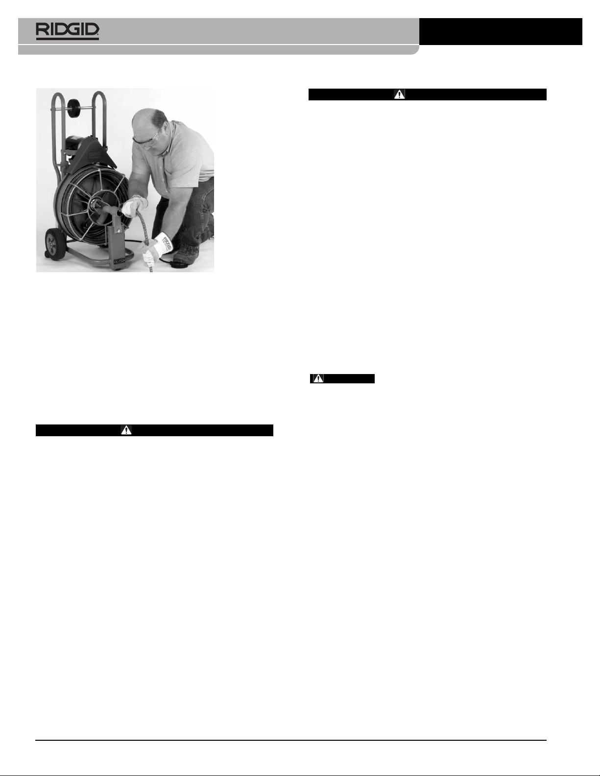
K-750R 5/8" Cage Machine
ment parts. Follow instructions in the Maintenance
Section of this manual. Use of unauthorized parts or
failure to follow maintenance instructions may create a
risk of electrical shock or injury.
Specific Safety Information
WARNING
Read this operator’s manual carefully before using
the RIDGID K-750R Drain Cleaner. Failure to under-
stand and follow the contents of this manual may
result in electrical shock, fire, and/or severe per-
sonal injury.
Call Ridge Tool Company, Technical Service at (800)
519-3456 if you have any questions.
Drain Cleaner Safety
•Wear gloves provided with the machine. Never
grasp a rotating cable with a rag or loose fitting
cloth glove. Could become wrapped around the cable
and cause serious injury.
•Never operate machine with belt guard removed.
Fingers can be caught between the belt and pulley.
•Do not overstress cables. Keep two hands on the
cable for control when machine is running.
Overstressing cables may cause twisting or kinking
and result in serious injury.
•Position machine within three feet of inlet. Greater
distances can result in cable twisting or kinking.
•Machine is designed for one person operation.
Operator must control foot switch and cable.
•Use foot switch to operate machine while main-
taining good footing and balance. Do not operate
machine in (REV) reverse. Operating machine in
reverse can result in cable damage and is used only to
back tool out of an obstruction.
•Keep hands away from rotating drum and guide
tube. Do not reach into drum unless machine is
unplugged. Hand may be caught in the moving parts
resulting in serious injury.
•Use kickstand during operation. The kickstand sta-
bilizes machine to prevent tipping.
•Do not use this machine in drains where cleaning
compounds have been used. Serious burns can
result from some drain cleaning compounds.
•Do not operate machine if operator or machine is
standing in water. Will increase the risk of electrical
shock.