Mastervolt MAGIC 12/12-20 User manual

Product description
The DC-DC converter MAGIC converts a DC-voltage into
another stabilized DC-voltage with a full galvanic isolation
between the input and output.
Applications
It offers you the following applications (see drawings
“INSTALLATION”):
MAGIC 24/12-20A (part no. 81300100)
•Drawing 1A, 1B: a stabilized 13.6V DC power supply
/ single stage float charger (e.g. to supply 12V
equipment from a 24V system), or
•Drawing 2A, 2B: a three-stage battery charger to
charge a 12V battery from a 24V system fully
automatically, or
•Drawing 3A, 3B: a 24/36 converter without galvanic
isolation, where the input is connected in series with
output.
•Drawing 4: a dimmer for 12V lights
MAGIC 24/24-20A (part no. 81300200)
•Drawing 1A, 1B: a 27.2VDC stabilized DC power
supply / single stage float charger (e.g. for a galvanic
isolation of the vehicle’s electrical system)
•Drawing 2A, 2B: a three-stage battery charger to
charge a 24V battery from a 24V system fully
automatically, or
•Drawing 3A, 3B: a 24/48V converter without galvanic
isolation, where the input is connected in series with
output.
•Drawing 4: a dimmer for 24V lights
MAGIC 12/12-20A (part no. 81300400)
•Drawing 1A, 1B: a 13.6VDC stabilized DC power
supply / single stage float charger (e.g. for a galvanic
isolation of the vehicle’s electrical system)
•Drawing 2A, 2B: a three-stage battery charger to
charge a 12V battery from a 12V system fully
automatically or
•Drawing 4: a dimmer for 12V lights.
MAGIC 12/24-10A (part no. 81300300)
•Drawing 1A, 1B: a 27.2V stabilized DC power supply
/ single stage float charger (e.g. for a galvanic
isolation of the 24V system), or
•Drawing 2A, 2B: a three-stage battery charger to
charge a 24V battery from a 12V system fully
automatically, or
•Drawing 3A, 3B: a 12/36V converter without galvanic
isolation, where the input is connected in series with
output.
Safety regulations and measures
1. Install the converter according to the stated
instructions.
2. Never use the converter at a location where there is
danger of gas or dust explosions.
3. Connections and safety features must be executed
according to the locally applicable regulations.
4. The converter may only be taken into operation while
the cover is closed as lethal voltages may exist.
The converter is provided with a non-replaceable input
fuse. If the plus and minus connections on the battery are
exchanged, the converter will become irreparable.
Do not use fuses larger than those indicated in the
specifications.
Installation
•Be sure that the output of the supplying source is
switched off during installation. Also be sure that no
consumers are connected to the batteries during
installation, to prevent hazardous situations.
•Check that the battery voltage is the same as the
converter’s input voltage (e.g. 24V battery for a 24V
input voltage). Also check that the output voltage
satisfies loading requirements
•Due to possible moisture accumulation and optimal
heat discharge, the converter must be installed in a
well-ventilated room protected against rain, vapour,
moisture and dust. We advise to mount the unit in a
vertical position with the connecting cables downward.
•Integrate a fuse in the positive wiring and place it
nearby the battery. See specifications for the
recommended fuse.
•Do not install the DC-DC converter straight above the
batteries because of possible corrosive sulphur
fumes.
Settings
There is no need to change the settings if the converter is
used as a stabilized DC power supply. Inside the
converter four DIP switches can be found to adjust the
converter according to your personal preferences. (see
table “DIP SWITCH SETTINGS”).
To adjust the DIP switches, proceed as follows:
1. Be sure the converter is disconnected from any
power source;
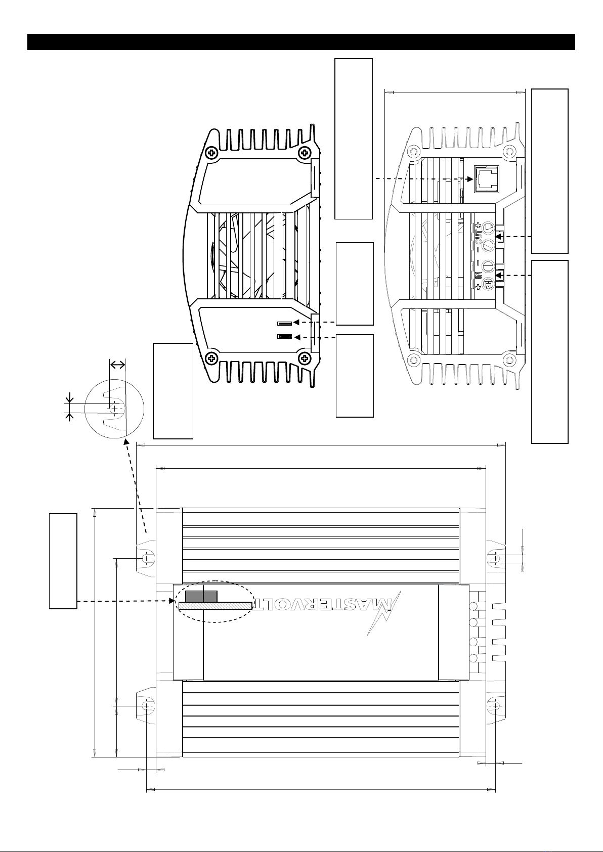
2. Remove the back cover of the converter by loosen
the four screws (see drawing “DIMENSIONS”);
3. Use a small flat-blade screw driver to change the
DIP-settings;
4. Remount the back cover again.
When more converters are paralleled to increase the total
output current, DIP-switches 1, 2 and 4 must be set to
the “OFF”-position and DIP-switch 3 depended to the
preferred output voltage.

Connections
For correct connection - see drawings “INSTALLATION”.
•Use reliable cord end terminals to fix the wires to the
DC-input and –output.
•See specifications for the recommended wire size.
•To minimize any EMC-interference we advise to
connect the negative pole of the supplying battery to
the ground.
Connect a momentary switch between the “switch”-
connection and the DC-output ground if you want to use
the remote switch function and/or the light dimmer
function (see drawing 1B, 2B, 3B).
Alarm contact
The alarm contact, right side connection on the back
(see drawings “DIMENSIONS”), is connected to the
contact. The contact is activated and connected to the
output ground in a normal situation, and will be
deactivated if the input voltage is too low (default 10.0V
or 20.0V), if the input voltage is too high (default 16.0V
or 32.0V), in case of overload or short-circuit. The
contact is also deactivated when the MAGIC is switched
off.
Operation
The converter operates automatically. Under normal
circumstances, there is no need for operation. Despite
its low no-load consumption, the converter should be
disconnected from the supplying battery when it is not in
use to protect the battery from discharging.
Refer to table “SWITCH OPERATION” for explanation of
the remote switch function / dimmer operation.
SWITCH OPERATION
Short
Converter switches off.
Press again to switch
on.
Long
After 1 sec. the output
voltage slowly
decreases to 4V or 8V.
Press again to increase
the voltage
Extended functions
Via the “QRS232 communication port” various settings
can be adjusted in terms of software to your specific
demands (control software and interface not included).
Please mind that this plug is not intended for
connecting any remote panels or a battery
temperature sensor.
Battery charger
Three-stage charge curve: Stage A: BULK, for quick
charging from 0 to 80%, Stage B: ABSORPTION, the
battery is charged from 80 to 100%. Stage C: FLOAT,
battery is maintained in fully charged state.
Guarantee terms
Mastervolt guarantees that this converter was built
according to the legally applicable standards and
stipulations. During production and before delivery all
converters were exhaustively tested and controlled. If
you fail to act in accordance with the regulations,
instructions and stipulations in this user’s manual,
damage can occur and/or the converter will not fulfil the
specifications. This may mean that the guarantee will
become null and void.
The guarantee period is 2 years.
Liability
Mastervolt cannot be held liable for:
•Consequential damage resulting from the use of the
converter.
•Possible errors in the included manual and the
consequences of these.
•Use that is inconsistent with the purpose of the
product

INSTALLATION 1A: STABILIZED VOLTAGE SUPPLY
INSTALLATION 1B: STABILIZED VOLTAGE SUPPLY WITH REMOTE SWITCH
U-out = 13.6V
-Stabilized DC-power supply / single stage
charger
DIP switch setting:
1 2 3 4
ON
OFF
U-out = 27.2V
1 2 3 4
ON
OFF
+ –
12V/24V
Load
U-out=
0V / 13.6V or
0V / 27.2V
+ –
12V/24V
U-out=
0V / 13.6V or
0V / 27.2V
DIP switch setting:
-Stabilized DC power supply with remote switch function
ON
OFF
1 2 3 4
Remote switch function ON
U-out = 13.6V
ON
OFF
1 2 3 4
U-out = 27.2V
ON
OFF
Load
Rear side

INSTALLATION 2A: 3-STEP BATTERY CHARGER
INSTALLATION 2B: 3-STEP BATTERY CHARGER WITH REMOTE SWITCH
-Automatic 3-step battery charger
+ –
12V/24V
+ –
12V/24V
Load
ON
OFF
24V battery charger,
3-STEP CHARGE, I= 80%
+ –
12V/24V
DIP switch setting:
-Automatic 3-step battery charger with remote switch function
ON
OFF
1 2 3 4
+ –
12V/24V
Load
12V battery charger, 3-STEP CHARGE, I= 80%
Remote switch function ON
ON
OFF
ON
OFF
24V battery charger, 3-STEP CHARGE, I= 80%
Remote switch function ON
Rear side
DIP switch setting: 3 stage charger.
12V battery charger,
3-STEP CHARGE, I= 80%
1 2 3 4
ON
OFF

INSTALLATION 3A: 12/36, 24/36 OR 24/48 CONVERTER
INSTALLATION 3B: 12/36, 24/36 OR 24/48 CONVERTER WITH REMOTE SWITCH
+ –
U-battery
U-out=
0V/ Ubat+13.6V
or
0V/ Ubat+27.2V
DIP switch setting:
- A 12/36, 24/36 or 24/48V converter without galvanic insulation with remote switch function
ON
OFF
Load
Model
MAGIC 12/24-10
MAGIC 24/12-20
MAGIC 24/24-20
U-battery
12V
24V
24V
U-out
U-battery + 27.2V
U-battery + 13.6V
U-battery + 27.2V
I-out
10A
20A
20A
ON
OFF
Rear side
- A 12/36, 24/36 or 24/48V converter
without galvanic isolation.
DIP switch setting:
+ –
U-battery
U-out=
0V / Ubatt+13.6V
or
0V / Ubatt+27.2V
Load
Model
MAGIC 12/24-10
MAGIC 24/12-20
MAGIC 24/24-20
U-battery
12V
24V
24V
U-out
U-battery + 27.2V
U-battery + 13.6V
U-battery + 27.2V
I-out
10A
20A
20A
ON
OFF

INSTALLATION 4: DIMMER
DIP SWITCH SETTINGS
# 1 Activate → ON 2 Activate → ON
3 12V→ OFF
24V→ ON
4 Activate → ON
Function
Dimmer function
3-step charge mode
Output voltage
13.6V / 27.2V
Remote switch
ON
OFF
Default: OFF
+ –
12V/24V
U-out = 4.0…13.0V
Dimmer and remote switch function ON
U-out = 8.0…26.0V
Dimmer and remote switch function ON
U-out=
4.0…13.0V /
8.0…26.0V
1 2 3 4
Dimmerconfiguration for 12 or 24Vhalogen lights with remote switch function
DIP switch setting:
ON
OFF
ON
OFF
Rear side

DIMENSIONS
•Remove the back cover to change the
DIP-settings (see text)
QRS232 communication port
(For extended functions)
OUTPUT / UITGANG / SORTIE
AUSGANG / SALIDA / USCITA
INPUT / INGANG / ENTRÉE
EINGANG / ENTRADA / ENTRATA
154 [6.1]
91 [3.6]
31,5
215
Detail A : Mounting
holes
8
[0.3]
5
[0.2]
6
[0.25]
203 [8.0]
227 [8.9]
DIP switches
81 [3.2]
Remote Switch
Alarm contact
Dimensions in mm [inch]
5
[0.2]
6
[0.25]

SPECIFICATIONS MAGIC
Model MAGIC 24/12-20A MAGIC 24/24-20A MAGIC 12/12-20A MAGIC 12/24-10A
Part no. 81300100 81300200 81300400 81300300
Nominal input voltage 24V 24V 12V 12V
Input range, full output specifications 19-32V DC 19-32V DC 11-16V DC 11-16V DC
Input range, three step charger mode 24-32V DC 24-32V DC 12-16V DC 12-16V DC
Input range, no defects 0-35V DC 0-35V DC 0-17.5V DC 0-17.5V DC
Low voltage set point to trigger alarm * 20.0V DC 20.0V DC 10.0V DC 10.0V DC
Delay lower input set point * 30 sec. 30 sec. 30 sec. 30 sec.
Recommended fuse input 15A-T 30A-T 30A-T 30A-T
Wire size < 3m 4mm²/AWG11 6mm²/AWG9 6mm²/AWG9 6mm²/AWG9
Wire size > 3m 6mm²/AWG9 10mm²/AWG7 10mm²/AWG7 10mm²/AWG7
Output
Voltage adjustable * 10-15V DC 20-28.5V DC 10-15V DC 20-28.5V DC
Nominal voltage stabilized voltage * 13.6V DC 27.2V DC 13.6V DC 27.2V DC
Output voltage 3 step charger
Absorption / Float 14.25 / 13.25V DC 28.5 / 26.5V DC 14.25 / 13.25V DC 28.5 / 26.5V DC
Output voltage dimmer 4.0-13.0V DC 8.0-26.0V DC 4.0-13.0V DC 8.0-26.0V DC
Stabilized 2% at extremes of temperature, load and input
Ripple Max 1% peak peak
Maximum power 300W @ U
out
=12.0V 580W @ U
out
=24.0V 300W @ U
out
=12.0V 300W @ U
out
=24.0V
Rated power 300W @ U
out
=12.0V 580W @ U
out
=24.0V 300W @ U
out
=12.0V 300W @ U
out
=24.0V
Current max. (derating >40°C, 5%/°C) 20A 20A 20A 10A
Maximum 3 step charge current (bulk) 16A 16A 16A 8A
Wire size < 2m 6mm²/AWG9 6mm²/AWG9 6mm²/AWG9 4mm²/AWG11
General
Ambient operating temperature Guaranteed operation: 0°C to 60°C (derating above +40°C, 5% per °C); in practice: -20°C to 60°C/
guaranteed operation: 32 °F to 140 °F (derating above 104 °F, 3% per °F), in practice -4°F to 140 °F
Storage temperature -25°C to 85°C/ -13 °F to 185 °F
Operating humidity 95% max., non-condensing
Galvanic isolation Yes
Current limited Yes, I-max
Three stage battery charge option Yes (DIP switch setting).
Efficiency 90% (at nominal input voltage, full load) typical; 92% peak
No load consumption Typical <115mA
Protections
Over current Limited by current sensing circuit
Over heat Limited power by temperature sense circuit
Options
3 Step battery Charger Yes, all models, by means of DIP switch settings
Dimmer function Yes, by external momentary switch via fast-on connection. To be activated by DIP-switch setting
Alarm contact Yes (fast-on connector)
Communication Quasi RS232, modular RJ12 connection, to alter set points and to change characteristics. Optional:
MasterBus serial interface (art. no. 77030450) to control & configure from MasterBus network.
Parallel connectability In mode Stabilized Voltage, up to 6 devices in parallel
Mechanical
Connections input/output Screw terminals, maximum wire size 16mm² / AWG 5
Dimensions (HxWxD) 227 x 154 x 81 mm [8.9 x 6.1 x 3.2 inch]
Mounting holes Diameter 5mm
Weight 1.8 kg / 3.9 lbs
Cabinet Anodized aluminium, strapton ABS blend, blue RAL 5021
Directives and standards: - EMC directive 2004/108/EC
- Transient voltage protection: meets ISO 7637-2
- Electrostatic voltage protection: meets ISO10605, 14892, 8kV contact, 15kV discharge
- RoHS directive 2011/65/EC
Setpoints software Default setting
Low input voltage switch off level 10.0V / 20.0V; three step charger mode:12.0VDC / 24.0VDC.
Low input voltage switch off delay 30 seconds
Low input voltage switch on level 11.0V / 22.0V; three step charger mode: 13.0VDC / 26.0VDC.
High input voltage switch off level 16.0V / 32.0V
High input voltage switch on level 15.0V / 30.0V
Output voltage 13.6V / 27.2V

EC DECLARATION OF CONFORMITY
We,
Manufacturer: Mastervolt
Declare under our sole responsibility that:
Product:
81300100 MAGIC 24/12
81300200 MAGIC 24/24
81300400 MAGIC 12/12
81300300 MAGIC 12/24
Is in conformity with the following provisions of the EC:
2004/108/EC EMC directive.
The following harmonized standards have been applied:
•EN 61000-6-1:2007: Immunity for residential, commercial and light-industrial
environments
•EN 61000-6-3: 2007: Emission standard for residential, commercial and light-
industrial environments
2011/65/EC RoHS directive
Amsterdam,
8 January 2012
Marc Persoon
Product Manager Power Conversion products
MASTERVOLT
Learn more about boat electrical on our website.
Other manuals for MAGIC 12/12-20
1
This manual suits for next models
4
Table of contents
Other Mastervolt Media Converter manuals