1 General Information
1.1 Wireless light alarm annunciator
«
Trubach-T-RK
»
(hereinafter, the
annunciator) is designed to provide evacuation management in case
of fire break-out or other extreme event.
1.2 Variants of caption:
-
-
-
-
1.3 The annunciator is intended for operation as a component of a
system, that is operated by a control panel (hereinafter, CP), supporting
«
Rielta-Contact-R
»
wireless two-way data exchange protocol.
1.4 Two frequencies in the 433.05 to 434.79 frequency range are
used for wireless signal exchange with the CP: the main frequency and
the reserve one. The annunciator switches to the reserve operating
frequency automatically in case of radio-frequency interference on
the main one.
1.5 Transmitter power does not exceed 10 mW.
1.6 The annunciator is powered in two ways:
a) by two CR123A/3V batteries, the main and the backup one;
b) by external uninterrupted power supply.
1.7 The annunciator generates and transmits the following messages
via radio channel:
-
«
NORM
»
;
-
«
Tamper
»
– after TEST button pressing;
-
«
Main power supply low-battery
»
– in case of the main battery
power supply discharge lower than 2.5-0.3 V or external power supply
drop lower than 9-2 V;
-
«
Backup power supply low-battery
»
– in case of the backup battery
power supply discharge lower than 2.5-0.3 V;
-
«
Announcing
»
– if annunciator is switched on.
1.8 The following rates of radio exchange sessions of the annunciator
status message transmission is assigned by a command from the control
panel (hereinafter, the CP): 10, 15, 30 sec, 1, 5 or 10 min.
1.9
«
Announcing
»
mode switching ON/OFF as well as annunciator
operation mode adjustment are fulfilled by relevant commands from
the CP.
1.10 The annunciator provides operation in continuous or pulsed
light-alarm modes.
1.11 Pulse-mode parameters can be set by the user in the process
of the annunciator adjustment.
1.12 The annunciator operation mode is displayed by two LED
indicators – red and green (see Table 3).
1.13 The annunciator ensures safe operation in standby mode*:
- in case of main battery power supply – not less than 6 years or 10
hours in continuous announcing mode;
- in case of backup power supply – not less than 2 months.
1.14 The annunciator is designed for continuous operation around
the clock in closed premises.
1.15 The annunciator is resistant to electromagnetic interferences,
electrostatic discharge and nanosecond pulse interferences.
2 Specifications
Table 1
Parameter Value
External power supply (12 ± 3) V DC
Current consumption in Announcing mode under:
- C123A power supply
- external power supply
85 mА
100 mА
Average current in standby mode under:
- C123A power supply
- external power supply
10 µА
8 mА
Operating temperature under:
- C123A power supply
- external power supply
from minus 20 … +55 °C
from minus 30 … +55 °C
Permissible humidity at 40 °C 93 %
Ambient class Boreal climate**
IP rating IP44
Dimensions, not more than
330 х 150 х 62 mm
Weight, not more than 0.45 kg
Average service life 10 years
3 Scope of Delivery
Each annunciator unit package contains items listed in Table 2.
Table 2
Name QNT
Wireless light alarm annunciator «Trubach-T-RK»
Screw 3-3х30.016
Wall NAT «SORMAT» 5x25
CR123A power supply battery
Wireless light alarm annunciator «Trubach-T-RK». Installation
Guide
1 pc.
2 pcs.
2 pcs.
2 pcs.
1 copy
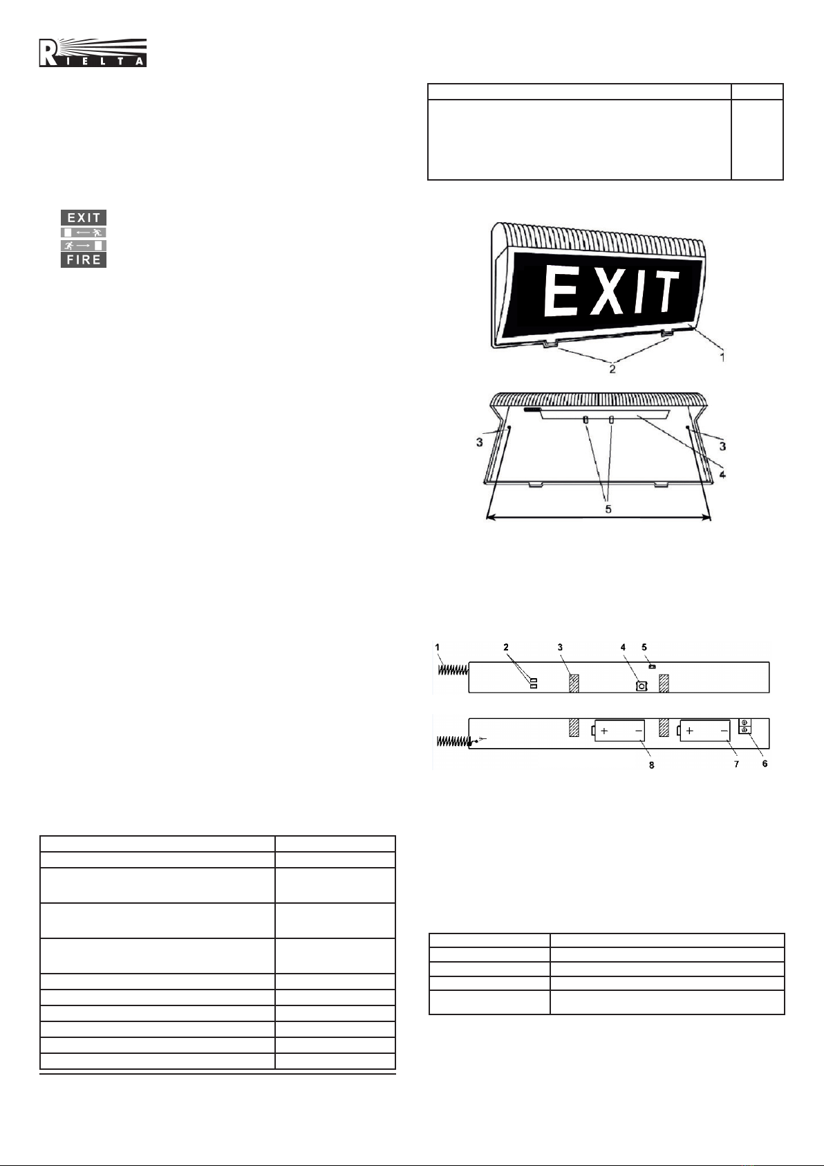
4 Design
Installation Guide
WIRELESS LIGHT ALARM
ANNUNCIATOR
«Trubach-T-RK»
1 – antenna;
2 – LED indicators;
3 – correct installation marks;
4 –
«
TEST
»
button;
5 –
«
RESET
»
male pins contacts;
6 – external power supply leading-in socket;
7 – backup power supply battery;
8 – main power supply battery.
Figure 2 – PCB
5 LED Indication
Table 3
Operation Mode LED Indication
Binding LED indicator blinking green
«Binding is completed» Short-term (2 sec) LED indicator lighting red
«Identification» Alternate LED indicator lighting green and red
«Communication Quality
Appraisal» See Table 4
6 Binding with the CP
The binding procedure is intended for logging of the Detector in the
CP and transmitting of service information to it.
6.1 Prepare the CP for the Detector binding in accordance to the
CP manual.
6.2 Remove the Detector cover. For this purpose press the cover
latches by screwdriver.
*) – provided that radio transmitting period is not less than 30 sec;
**) – background temperature 15 – 35 оС, relative humidity 25 – 75 %,
air-pressure 86 – 106 kPa.
Without cover
With cover on
1 – cover;
2 – cover latches;
3 – mounting holes;
4 – printed circuit board (PCB);
5 – PCB holders.
Figure 1 – Annunciator case
300 mm
Front side
Opposite side
G
R
MAIN BACKUP
RESET
-12V+
TEST
Т-Т-RK v10.1


