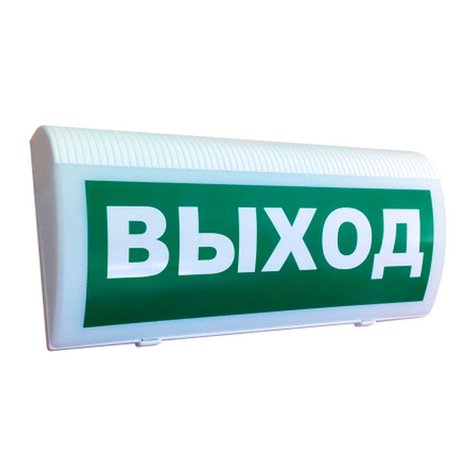
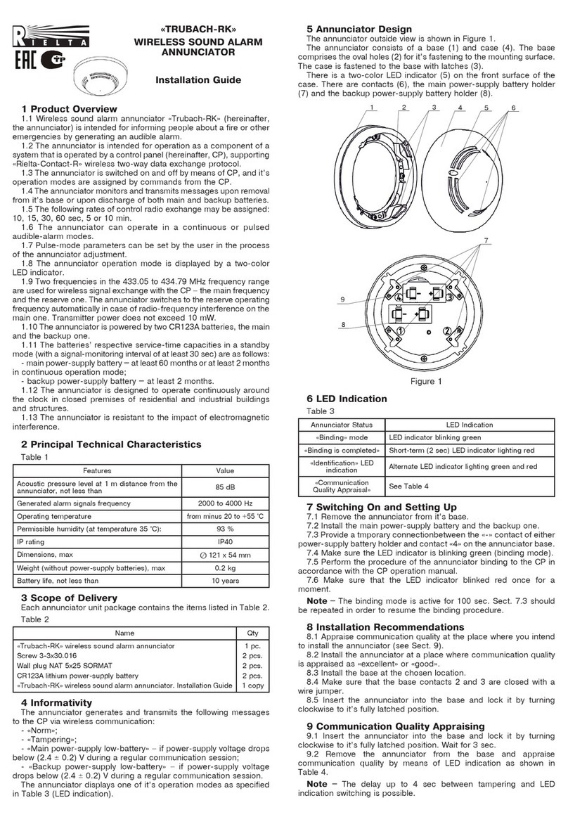
Rielta TRUBACH-U-RK User manual

1 General Information
1.1 Wireless combined outdoor siren «Trubach-U-RK» (hereinafter, the
Siren) is designed for informing people about events and emergencies by
generating light and acoustic signals.
1.2 The Siren is intended for operation as a component of a system
that is operated by a control panel (hereinafter, CP), supporting «Rielta-
Contact-R» wireless two-way communication data exchange protocol.
1.3 Wireless signal exchange with the CP is executed via two-way
addressable wireless communication within the 433.05 to 434.79
frequency range. Two frequencies in are used for the radio exchange: the
main frequency and the reserve one. The Siren switches to the reserve
operating frequency automatically in case of radio-frequency interference
on the main one.
1.4 Transmitter power does not exceed 10 mW.
1.5 The Siren is powered either by two lithium batteries CR123A type
with 3V nominal voltage located inside a case, or from external power
supply with nominal voltage 9 – 30V.
If power is supplied from both sources (batteries and external power
supply), the Siren is out of service!
1.6 The Siren generates and transmits the following messages via radio
communication channel:
- «Norm»;
- «Tamper» – after case tampering;
- «Main power supply failure» – if power-supply battery voltage drops
below (3,5 ± 0,5)V or external power supply voltage drops lower than (8
± 1) V;
- «Backup power-supply failure» – if power-supply voltage drops below
(3.2 ± 0.5) V;
1.7 The following rates of control radio exchange may be assigned
by the command from CP: 10 s, 15 s, 30 s, 60 s, 2 min, 5 min. Alarm
messages are transmitted immediately.
1.8 Siren switching ON / OFF and modes of its operation adjustment are
executed by commands from the CP.
1.9 Siren provides continuous and pulse alarm modes.
1.10 User is able to set pulse mode parameters.
1.11 The Siren provides light signal contrast at illumination level up to
500 lk.
1.12 Operation modes of the Siren are displayed by two LED indicators
(see Table 3).
1.13 The Siren being powered by built-in power supply battery ensures
safe operation in standby mode for not less than 8 years.
1.14 The Siren is designed to operate continuously around the clock in
closed premises of residential and industrial buildings and structures, as
well as at open areas under the roof.
1.15 The Siren is resistant to the impact of electromagnetic interference.
2 Principal Technical Characteristics
Table 1
Parameter Value
Acoustic pressure level at 1 m distance from the Siren,
not less than
95 dBA
Generated acoustic signals frequency 2 … 5 kHz
Average consumption current in a standby mode:
- in a battery mode*, not more than
- in external power supply mode, not more
16 µA
5 mA
Average consumption current in an acoustic alarm
mode (both: in battery or in external power supply
modes), not more than
280 mA
Average consumption current in a light alarm mode:
- in a battery mode*, not more than
- in external power supply mode, not more
200 mA
100 mA
IP rating IP54
Dimensions, not more than
220х330х90 mm
Weight, not more than 1 kg
Average service life 8 years
Operating conditions
Operating temperatures:
- in a battery mode
- in external power supply mode
-20...+55 °C
-40...+55 °C
Permissible moisture at a temperature +25 °C 100 %
______________
* – with a radio exchange interval of at least 60 s, radio interference absence
and normal operational conditions at a temperature +25 °C
3 Scope of Delivery
Each Siren unit package contains the items listed in Table 2
Table 2
Name QNT
Wireless combined outdoor siren «Trubach-U-RK»
Screw 3-3х40.016
Wall plug NAT 8x40 «SORMAT»
Lithium power supply battery CR123A
Wireless combined outdoor siren «Trubach-U-RK».
Installation Guide
1 pc.
2 pcs.*
4 pcs.
4 pcs.
1 copy
* – Installed
4 Protective Measures
Dangerous voltages for human health are absent in the Siren.
5 Design
The Siren layout is shown in figure 2 .
Case comprises the following components:
- base (1);
- cover (2), fixed by 2 screws (3)
The base contains:
- four mounting holes (4) to the wall;
- pieso-transmitter (5);
- tamper contacts (6);
- PCB in transparent protective case (8);
Protective case includes:
- battery compartment (7), with a cover with 2 latches (10)
- two-colour LED indicators (9)
WIRELESS COMBINED
OUTDOOR SIREN
«TRUBACH-U-RK»
Installation Guide
0
о
30
о
60
о
90
о
30
о
90
о
60
о
76 82 88 94 100
dB
A typical directional pattern (horizontal and vertical) of the sound
channel of the sounder is shown in Fig. 1.
Figure 1 – A typical directional pattern
Figure 3 – Battery compartment
Figure 2 – «Trubach-U-RK»
4 4
5
6
7
10
8
4
4
2
3
1
RESET
-12V+
BAT
BAT
+
+
–
–
9
Battery compartment (Figure 3) stores:
- «RESET» pin contacts;
- two lithium batteries with one isolator and leading-in socket for external
power supply «-12V+».
Isolator
6 LED Indication
The Siren displays its state by the LED indication as it shown in Table
3.

Table 3
Operation Mode LED Indication
Binding Green LED intermittent blinking
Binding is finished Short-run (2 s) red LED continuous lighting
Identification Alternate green and red indicators blinking
Communication Quality See Table 4
7 Switching On and Pre-starting Procedures
In general the operating procedure comprises the following steps:
- binding with the CP (logging in the CP);
- choosing place of installation and communication quality apprising;
- installation.
8 Binding with the CP
8.1 Prepare the CP for new equipment binding (Binding mode) in
accordance with the CP Manual. During binding procedure in radio
coverage zone there must be only one CP which is ready for binding with
the new device.
8.2 Remove port plugs from screws (Fig.2 pos.3). Untighten the screws.
Holding the base, pry off the case cover from the lens side (Fig.4) and
put it off.
Remove cover of the Siren battery compartment holding latches pressed.
12 Overall Mounting Dimensions
13 Storage and Transportation
13.1 The storage premises should not contain any current-conducting
dust, acid and alkali fumes, or corrosive or destroying insulation gases.
13.2 The Siren in its original packing may be shipped by any transport
means in closed vehicles that assume transportation over any distances
in compliance with the existing shipping rules concerning the respective
means of transportation.
13.3 During storage and transportation periods lithium battery must be
removed from the holder or an isolator should be inserted between “+”
battery contact and a holder.
13.4 After transportation under the conditions different to exploitation
conditions, the Siren shall be ready to operate after a maximum of six
hours.
14 Reclaiming
14.1 The Siren reclaiming is fulfilled taking into account the absence of
toxic components in it.
14.2 Reclaiming of batteries is performed according to the rules of
disposal of batteries.
15 Manufacturer’s Guarantees
15.1 The manufacturer guarantees conformity of the «Trubach-U-
RK» to its Technical Specifications during 42 months since the date of
manufacture provided that the transportation, storage, installation and
operation conditions are observed.
15.2 The guaranteed shelf life of the «Trubach-U-RK» is 36 months
since the date of manufacture within the limits of guaranteed shelf life.
15.3 The «Trubach-U-RK» that is found non-conforming to the
Technical Specifications shall be repaired by the manufacturer, provided
the installation and operation rules have been complied with.
15.4 Warranty obligations are not applied to the power supply batteries.
Rev. 0 of 02.04.20
v10.2
Made in Russia
«RIELTA» JSC, www.rielta.com,
Tel./fax. +7 (812) 233-0302, 703-1360,
220
330
87
154
163
268
26
26
Figure 5
Рисунок 4
8.3 Remove isolating film between “+” contact and
lithium battery holder or energize the Siren by an external
power supply.
8.4 Close “RESET” pin-contacts on the printed circuit
board (PCB) by current-conducting item until indication
“Binding” is switched on.
8.5 Execute binding procedure. Successful binding is
displayed by short-run red LED indicator binding.
NOTE – The binding mode is active for 100 seconds.
In order to resume the binding procedure Cls. 8.4, 8.5
should be repeated.
9 Choosing place of installation
9.1 It is not recommended to install the Siren in the
following places:
- on massive metal constructions and closer than 1m
to them;
- closer than 1m to power cables and metal water and gas pipes;
- near radio interference sources;
- inside metal constructions.
9.2 Install the Siren at a place where communication quality is appraised
as «excellent» or «good» (see Cl. 10).
10 Communication Quality Appraising
10.1 Bring binded Siren to the chosen place of installation.
10.2 Press and then release tamper contacts for 1 s (Fig.2, pos.6).
10.3 Apprise communication quality with the CP by LED indication modes
in accordance with Table 4.
Table 4 – LED indication of communication quality control results
LED Indication Communication
Quality
Appraisal
Recommendations
Color Mode
Green Three blinks Excellent Install the Siren at
this place
Green Two blinks Good
Green One blink Communication
established
Choose another
place for installation
or use repeaters of
«Ladoga-RK» product
line
Red A series of blinks No
communication
11 Installation
11.1 Choose a place for installation, mark places for the Siren fixation
(Figure 5). Use the Siren case as a template for marking.
11.2 Fasten the Siren with the removed cover in the chosen place by
means of tap screws using 4 fixation holes.
11.3 Install the cover and fix it by 2 screws.
11.4 Put port plugs on the screws.
Other Rielta Security System manuals
Popular Security System manuals by other brands

Tiiwee
Tiiwee X4 Motion Sensor Alarm user manual

GreatCall
GreatCall lively quick start guide

First Alert
First Alert Bark Genie FABCU1 Series instruction manual

Bose
Bose Videobar VB1 manual

PSR
PSR PAT ANTI-TWO-BLOCK INSTALLATION, OPERATOR’S & TROUBLESHOOTING MANUAL

HIK VISION
HIK VISION DS-PF-E0204 Series Product Instruction

Johnson Controls
Johnson Controls Tyco PowerSeries Pro HS3032 Reference manual

Vigilant
Vigilant MX1 Operator's manual

Autronica
Autronica AutroVoice miniVES Series Service manual

Goscam
Goscam 8104JR user manual

SVAT
SVAT Do-It-Yourself Compact DVR Security System... instruction manual

Karassn
Karassn KS-858G user manual