Operating Manual
Breite: 170
Höhe:8,15
Oben Links
278,5 20
RIFOX - Hans Richter GmbH Spezialarmaturen Fon: +49 (0) 421 499 75 - 0 Internet: www.rifox.de
Bertha-von-Suttner
-Str
.
9
D-28207
Bremen
Fax:
+49
(0)
421
499
75
-
40
Email:
[email protected]06/2020
Page 4 of 6
-Di. Subject to modifications
3.4 Installation
■The condensate trap Vario 1222 has to be screwed or welded into a pipeline between flanges.
■Remove transport caps from inlet and outlet.
■Fitting direction: according to Picture 5. The condensate flow is in the direction of the arrow (note arrow on housing
flange (1) ). The housing is positioned to the side. The word TOP on the housing is at the top and must be legible horizontally.
■Supporting brackets: Ensure proper fixing of the pipeline in front of and behind the condensate trap.
■To avoid downtimes, it is recommended to install stop valves with bypass to pipeline, both in front of and behind the con-
densate trap.
4 Start-Up
The pressure build-up and heating-up of the housing should not take place abruptly. If leakage is detected after the first
inspection, the screws (4 / 5 / 6 / 10) can be fixed under consideration of the given torque moments, as given in Section
6.7. The screws can only be tightened on when the housing is unpressurized and hand warm.
5 Observation and control
The function’s failure can be observed either as condensate blockage or as gas/ steam leakage.
■Condensate blockage can be determined by a): loosen the control screw (4) for a quarter rotation, while no condensate
leakage should occur; and by b): a surface thermometer on the housing for steam applications (if necessary, consult with
Rifox).
■Gas / steam leakage: can be determined by an ultrasonic measuring device, and for steam applications by a surface
thermometer. In case of steam leakage, open the condensate trap according to Section 6.1. Make sure that float can be easily
moved. If necessary, disassemble and clean the float control assembly. If damages/ wears are detected on parts or on the
sealing surface, the complete float control assembly should be replaced.
6 Maintenance / Inspection
6.1 Opening the condensate trap and dismantling the float control assembly
■The steam trap can not be dismantled from the pipeline system.
■The condensate trap must be depressurized. Shut off the system before and after the condensate trap.
■Release any remaining pressure by loosening the control screw (4) by only a quarter turn.
■Loosen the housing screw (5) evenly crosswise and take off housing side part (3).
■Unscrew the supporting screw (10) for 1-2 turns.
■With a few light strokes using plastic hammer on the front side of the supporing screw (10) to loosen the float control
assembly (7) from its conic housing seat.
■Screw out the supporting screw (10) completely. Remove the float control assembly (7).
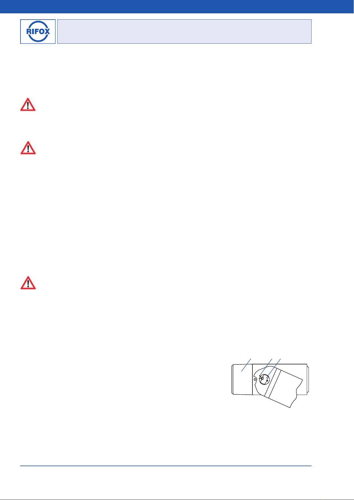
6.2 Disassembling, cleaning and assembling the float control (Picture 6)
■After removing the cotter pin (p), the rotary valve (v) can be simply pulled out to
the side.
■Clean the parts using, for example, benzine.
■Check the rotary valve (v) for wear along the sealing edge. If wear is detected, the
support body (b) and the rotary valve (v) must be replaced. A thorough leakage test
must be carried out by Rifox.
■During assembling ensure that the notch in the rotary valve (v) points to the punch
mark on the support body (b) and the cotter pin (p) is inserted and secured again
carefully.
■The float must be able to be moved up and down by hand easily.
bpv
Picture 6