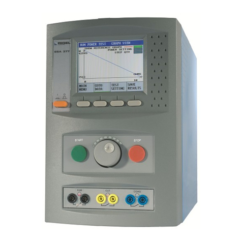
Large colour graphic isplay
On/Off Button
Function Keys F1 - F4
Rotary enco er for menu navigation
Start/OK Button
Stop/En Button
Front connection panel
Fol ing legs at front base of unit
Front connection panel
Getting to know your Rigel Uni-Therm
Connect the REM/plate security
electro es to the front panel for the REM test.
Connect the footswitch contacts to the front panel for automatic footswitch control.
Side connection panel
Connect the HF active an neutral electro es to
the si e panel using the on-screen connection
iagrams for reference.
The scope output can be use in conjunction with the a itional scope cable
accessory (P/N: 367A950) to view the waveform shape.
Rear panel
Ensure the ventilation holes are free from obstruction uring
operation to allow for maximum unrestricte air flow.
Power fuses are locate below the IEC connector.
2Before you switch on!
Ensure the correct incoming mains supply voltage range is selected
The mains selector switch is locate on the base of the unit. Please ensure this switch is
set to either 230V AC ± 10% or 120V AC ± 10% as require .
Ensure legs are deployed
The Rigel Uni-Therm has two legs at the front base of the unit. These are esigne to raise
the front of the unit to allow clear airflow for the base fan an also to improve the viewing
angle of the colour graphic isplay.
Ensure all ventilation holes are free from obstruction
The Rigel Uni-Therm has several fan an air vents locate aroun the casing.
Please ensure these are free from obstruction to allow for maximum air flow.
Active power connections
Ensure no active power electro es are connecte to the front panel of the Rigel Uni-
Therm. The front panel is for low voltage connections only (i.e. CQM connection or
footswitch)
Instruction Manual
This Quick Start Gui e is esigne to be use
in conjunction with the full Rigel Uni-Therm
instruction manual.
The Rigel Uni-Therm electrosurgical analyser
instruction manual is now provi e in electronic
format only.
The manual is inclu e on the utilities isc
which accompanie your evice an is also
available as a ownloa from rigelmedical.com
3Getting Started
In this section we will i entify the Rigel Uni-Therm electrosurgical analyser’s basic functions
in or er to get you starte .
From the setup menu select
Time/Date
Use the rotary enco er to
change the Time/Date an
press function key F4 to Save
Change the language settings Set the time/date
Select Setup
Select Language Scroll to the require language
an select to confirm
From the start screen use the
rotary enco er or function key
F1 to select Menu
Perform a test
REM Test
■Select the REM test from
the main menu;
■Select automatic or manual
control an press the green
button to start the test
(for automatic mo e only)
■To stop the test, press
CAPTURE ALARM.
HF Leakage Test
■Select the HF LEAKAGE
test from the main menu;
■Select the appropriate test
using the rotary enco er.
Change between the graph
mo e an escription mo e,
using the function keys.
Power Test
■Select the POWER test from
the main menu;
■Select either CONTINUOUS
or GRAPH mo e.
■Ensure that the settings (i.e.
CUT or COAG) correspon
with the connections as
these control the automatic
footswitch control.
Connections - Remember to
use the on-screen connection
iagrams as a reference for
connecting the active an
neutral electro es an test
links.
i
The Uni-Therm interface has been segmented into a safe, low voltage area (front panel)
and high voltage area (side panel)
Switch on
Turn on your Rigel Uni-Therm by pressing an hol ing the
green ON button until the Rigel splash screen appears.


