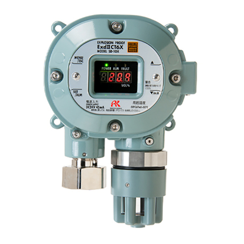
Riken Keiki SD-D58-AC User manual

PT2E-1739
Smart Transmitter/Gas Detector Head
SD-D58・AC
SD-D58・DC
(TYPE GP)
(TYPE NC)
(TYPE NCW)
(TYPE GP H)
(TYPE NC H)
Operating Manual

Operating Precautions
This detector head is a gas detector that detects combustible gases in the air and triggers a gas alarm.
The gas detector is a safety unit, not an analyzer or densitometer which performs quantitative/qualitative
analysis/measurement for gases.
Please fully understand the following points before using it, so that it can be used properly.
1. This detector head may be interfered by gases and vapors other than the gas to be detected.
Please note that the alarm may be triggered by interference. In addition, it may be fluctuated by
environmental (temperature, humidity, etc.) changes in the installation site.
2. The alarm must be set within a range where the performance of the detector head can be ensured.
In facilities compliant with the High Pressure Gas Safety Act, an alarm setting below our standard
alarm setpoint may trigger a false alarm.
3. This is a safety unit, not a control unit.
The alarm contact output of the detector head must be used for an external alarm lamp/buzzer, while
the alarm signal output must be used for an indicator or external recorder.
If these outputs are used to control other units, we shall not be responsible for any malfunctions.
4. The gas sensing part of the gas sensor installed in this detector head is made of metal porous sintered
alloy permeated with an oxidation catalyst.
If silicon or sulfide compounds are accumulated on the surface of porous sintered alloy, the area of the
gas sensing part becomes smaller, which may results in serious deterioration of its sensitivity.
For safety reasons, do not use the detector head under the presence of silicon or sulfide compounds
even though their amount is very small.
5. For maintenance of the detector head, it must go through a regular maintenance, including
replacement and adjustment of the regular replacement parts as specified in the operating manual. In
addition, because this is a safety unit, it is recommended that a regular maintenance and a gas
calibration are performed every six months in accordance with the regulations.

<Contents>
Outline of the Product............................................................................................................... 1
1-1. Preface..................................................................................................................................... 1
1-2. Purpose of use ......................................................................................................................... 1
1-3. Definition of DANGER, WARNING, CAUTION, and NOTE ...................................................... 2
1-4. Method of confirmation for Standards and Explosion proof specification ................................. 2
2. Important Notices on Safety..................................................................................................... 3
2-1. Danger cases ........................................................................................................................... 3
2-2. Warning cases.......................................................................................................................... 4
2-3. Precautions .............................................................................................................................. 5
2-4. Safety Information .................................................................................................................... 6
3. Product Components ............................................................................................................... 9
3-1. Main unit and standard accessories ......................................................................................... 9
3-2. Names and functions for each part........................................................................................... 11
3-3. Block diagram........................................................................................................................... 16
4. How to Use .............................................................................................................................. 18
4-1. Before using the detector head ................................................................................................ 18
4-2. Precautions for installation points............................................................................................. 18
4-3. Precautions for system designing............................................................................................. 19
4-4. How to install ............................................................................................................................ 22
4-5. How to wire .............................................................................................................................. 24
4-6. How to tube .............................................................................................................................. 33
5. How to Operate........................................................................................................................ 34
5-1. Preparation for start-up ............................................................................................................ 34
5-2. Basic operating procedures...................................................................................................... 35
5-3. How to start the detector head ................................................................................................. 36
5-4. Modes ...................................................................................................................................... 36
5-5. Maintenance mode (User)........................................................................................................ 38
5-6. How to exit ............................................................................................................................... 41
6. Operations and Functions........................................................................................................ 42
6-1. Gas alarm activation................................................................................................................. 42
6-2. Fault alarm activation ............................................................................................................... 43
6-3. Low Flow Rate Abnormal Operations ....................................................................................... 43
6-4. External output operation ......................................................................................................... 44
6-5. Other functions......................................................................................................................... 46
7. Maintenance ............................................................................................................................ 47
7-1. Maintenance intervals and items .............................................................................................. 47
7-2. Maintenance mode (Regular maintenance) ............................................................................. 49
7-3. Gas calibration method ............................................................................................................ 57
7-4. How to maintain flow sensor .................................................................................................... 64
7-5. Parts replacement .................................................................................................................... 65
8. Storage, Relocation and Disposal............................................................................................ 66
8-1. Procedures to store the detector head or leave it for a long time ............................................. 66
8-2. Procedures to relocate the detector head or use it again ......................................................... 66
8-3. Disposal of products................................................................................................................. 66
9. Troubleshooting ....................................................................................................................... 67
10. Product Specifications ............................................................................................................. 69
10-1. List of specifications ................................................................................................................. 69
10-2. Detection principle.................................................................................................................... 91
11. Definition of Terms ................................................................................................................... 93
1.

1 Outline of the Product 1-1. Preface
1
1
Outline of the Product
1-1. Preface
Thank you for choosing our smart transmitter/gas detector head SD-D58 series. Please check that the
model number of the product you purchased is included in the specifications on this manual.
This manual explains how to use the detector head and its specifications. It contains information required
for using the detector head properly. Not only the first-time users but also the users who have already used
the product must read and understand the operating manual to enhance the knowledge and experience
before using the detector head.
The detector head has five types of TYPE GP/TYPE NC/TYPE NCW and HART communication TYPE GP
H/TYPE NC H. In this manual, instructions of TYPE GP (such as an example of LED display) are
described as example.
1-2. Purpose of use
The detector head is a fixed type detector head that detects leak of combustible gases and that
performs the alarm activation when the gas concentration is over the setting value.
The detector head is a safety unit, not an analyzer or densitometer which performs
quantitative/qualitative analysis/measurement for gases. Please fully understand the features of the
detector head before using it, so that it can be used properly.
The detector head draws air with the built-in pump, and detects abnormalities in the air caused by
presence of gases or other reasons (leak) with the built-in gas sensor. The concentrations of detected
gases are displayed on the seven-segment LED.
The detector head has a built-in alarm contact and can be used either as a gas alarm, fault alarm, or
common (gas, fault) alarm.
The detector head has a built-in low flow rate detection function and can trigger a fault alarm when the
flow rate inside the tubing drops below a fixed rate.
The detector head outputs gas concentration in 4 – 20 mA.
SD-D58 series have two types of power supply specifications.
SD-D58・AC AC power specification 100 – 110VAC
SD-D58・DC DC power specification 24VDC
TYPE GP H/TYPE NC H have HART communication function.

1 Outline of the Product 1-3. Definition of DANGER, WARNING, CAUTION, and NOTE
2
1-3. Definition of DANGER, WARNING, CAUTION, and
NOTE
DANGER This message indicates that improper handling may cause death or serious
damage on health or assets.
WARNING This message indicates that improper handling may cause serious damage
on health or assets.
CAUTION This message indicates that improper handling may cause minor damage on
health or assets.
NOTE This message indicates advice on handling.
1-4. Method of confirmation for Standards and
Explosion proof specification
This instrument has some specification depends on standard and explosion proof certificate. Please
confirm the detector specification before using. Please refer Declaration of Conformity that is at the end of
this manual if you have CE marking type.You can confirm instrument specification to see name plate as
follows.
ATEX, CE marking type name plate TIIS type name plate
(DC power specification only) (AC/DCpowerspecification)
ITRI type name plate
(AC/DC power specification)
CE marking
Ex marking TIIS certificate
ITRI certificate

2 Important Notices on Safety 2-1. Danger cases
3
DANGER
<About explosion-proof>
The window plate material is a polycarbonate resin. Do not use organic solvents and alkali
types (liquid or vapor). It may cause the color and shape of the window plate to be changed.
The flameproof joints are not intended to be repaired.
Do not open the lid when applying current. The lid may be opened after five minutes or more
after power off.
Do not attempt to repair the detector head by the user.
For the lid, use hexagon socket head bolts specified by RIKEN KEIKI.
The drive lid must be closed during use (except during maintenance).
Chloroprene rubber (CR) is used for the components of the cable gland. The explosion-proof
performance may not be maintained depending on the organic solvent / alkali (liquid or vapor)
present in the measurement environment.
Do not repair or replace the explosion-proof contact surfaces. If scratches, cracks, deformation
etc. are seen on the container or explosion-proof joint surface, please stop using it immediately
and promptly contact the dealer or our nearest sales office.
2
Important Notices on
Safety
2-1. Danger cases

2 Important Notices on Safety 2-2. Warning cases
4
WARNING
Power supply
Before turning on the detector head, always check that the voltage is properly applied. Do not use
an unstable power supply because it may cause malfunctions.
Need of grounding circuit
Do not cut the grounding circuit or disconnect the wire from the grounding terminal.
Defects in protective functions
Before starting the detector head, check the protective functions for defects. When seeming
defects are found in the protective functions, such as protective grounding, do not start the detector
head.
External connection
Before connecting the detector head to the external control circuit, securely connect it to a
protective grounding circuit.
Zero adjustment in the atmosphere
When the zero adjustment is performed in the atmosphere, check the atmosphere for freshness
before beginning the adjustment. If other gases exist, the adjustment cannot be performed
properly, thus leading to dangers when the gas leaks.
Response to gas alarm
Issuance of a gas alarm indicates that there are extreme dangers. Take proper actions based on
your judgment.
Do not use the low flow rate alarm function under the presence of silicon.
Silicon may accumulate on the sensing part of the flow sensor, which can result in malfunction.
Do not use the low flow rate alarm function under the presence of corrosive gas
Corrosive gas (chlorine, sulfur, acid, alkaline, halogen) may corrode the flow sensor, which can
result in malfunction.
Do not use the low flow rate alarm function under the presence of high-concentrated gas
Under the presence of high-concentrated combustible gas over the lower explosive limit, the flow
sensor may be overheated, which can result in malfunction.
2-2. Warning cases

2 Important Notices on Safety 2-3. Precautions
5
CAUTION
Do not use a transceiver or such a device near the detector head.
Radio wave from a transceiver near the detector head or its cables may disturb indication reading.
If a transceiver is used, it must be used in a place where it disturbs nothing.
To restart the detector head, wait for five seconds or more before doing it.
Restarting the detector head within five seconds may cause errors.
Do not use the external output of the detector head to control other units.
This is not a control unit. It is not allowed to use the external output of the detector head to control
other units.
Do not disassemble/modify the detector head, or change the settings if not necessary.
Disassembling/modifying the detector head will invalidate the warranty of the performance.
Changing the settings without understanding the specifications may cause alarm malfunctions.
Please use the detector head properly in accordance with the operating manual.
Avoid applying organic solvents and others to the window plate for a long time.
The window plate material is a polycarbonate resin. When organic solvents (liquid or highly-
concentrated vapor) and others are applied to the plate for a long time, its color and shape may be
changed.
Never fail to perform a regular maintenance.
Since this is a safety unit, a regular maintenance must be performed to ensure safety. Continuing
to use the detector head without performing a maintenance will deteriorate the sensitivity of the
sensor, thus resulting in inaccurate gas detection.
Use the low flow rate alarm function only under the atmosphere of air or nitrogen.
The flow sensor measures the change of radiation amount caused by air current.
Different air type has a different radiation characteristic, which can result in malfunction.
For the following gas types and concentrations, the low flow rate warning function can not be used.
Example) argon, helium, and hydrogen > 5 vol %, carbon dioxide, propane, ethane > 50 vol %,
methane > 25 vol %
When using the low flow rate alarm function, use any filter depending on the operating
environment.
Otherwise dust and/or mist can cause clogging on the flow sensor, which can result in malfunction.
Set a dust filter and/or mist separator on the upstream side of tubing depending on the operating
environment.
2-3. Precautions

2 Important Notices on Safety 2-4. Safety Information
6
2-4. Safety Information
Necessary information for explosion proof construction of Model SD-D58・AC/SD-D58・DC.
The Model SD-D58・AC/SD-D58・DC is a fixed mount, continuous-monitoring detector head and provides
a 4-20mA signal which indicates the target gas reading for use by a gas monitoring controller, recording
device, or programmable controller.
There is one point of contact and works by gas warning or trouble or both by setting.
<ATEX Specifications>
Technical Data
(Protection Method) Flameproof enclosure “d”
(Group) II
(Category) 2G
(Type of Protection and Marking code) Ex db ⅡB+H2 T4
(Equipment Protection Level) Gb
(Ambient Temperature) -20C to +53C
(Electrical Data)
Supply voltage : 24Vdc(Typ.)
Output signal : 4 to 20 mA
Electrical rating : DC3.0V 430mA or DC5.0V 200mA
Flow rate element power output : DC2.0V 170mA
Analog signal output : DC24V 25mA
Relay (Contact output) : DC30V or AC250V 0.5A
(Applicable Standard) EN 60079-0 : 2012+A11:2013,EN 60079-1: 2014
Installation
【SD-D58・DC】
GND
Sig+
RLY
GND
Sig+
RLY
Indicator etc.
24V
GasDetector (SD‐D58・DC)
Hazardous Location
(Zone1)
Nonhazardous Location
InstallationDiagram
CVVSCable
24V

2 Important Notices on Safety 2-4. Safety Information
7
<ITRI Specifications>
Technical Data
(Protection Method) Flameproof enclosure
(Explosion-proof class) Ex d ⅡB+H2 T4 Gb X
(Ambient Temperature) Type AC: -20C to +50C
Type DC: -20C to +53C
(Electrical Data)
Supply voltage : Type AC: AC100-110V 50/60Hz 120mA
Type DC: DC24V 360mA
Electrical rating : DC3.0V 430mA or DC5.0V 200mA
Flow rate element power output : DC2.0V 170mA
Analog signal output : DC24V 25mA
Contact output : AC250V 0.5A(Load resistance)
DC30V 0.5A(Loadresistance)
(Applicable Standard) JNIOSH-TR-NO. 43(2008)
Installation
【SD-D58・AC】 【SD-D58・DC】
CVVSCable
Sig+
Sig‐
RLY
Sig+
Sig‐
RLY
Indicator etc.
ACPower
L
N
PE
GasDetector (SD‐D58・AC)
Hazardous Location
(Zone1)
Nonhazardous Location
InstallationDiagram
GND
Sig+
RLY
GND
Sig+
RLY
Indicator etc.
24V
GasDetector (SD‐D58・DC)
Hazardous Location
(Zone1)
Nonhazardous Location
InstallationDiagram
CVVSCable
24V

2 Important Notices on Safety 2-4. Safety Information
8
<TIIS Specifications>
Technical Data
(Protection Method) Flameproof enclosure
(Explosion-proof class) Ex d ⅡB+H2 T4
(Ambient Temperature) Type AC: -20C to +50C
Type DC: -20C to +53C
(Electrical Data)
Supply voltage : Type AC: AC100-110V 50/60Hz 120mA
Type DC: DC24V 360mA
Electrical rating : DC3.0V 430mA or DC5.0V 200mA
Flow rate element power output : DC2.0V 170mA
Analog signal output : DC24V 25mA
Contact output : AC250V 0.5A(Load resistance)
DC30V 0.5A(Loadresistance)
(Applicable Standard) JNIOSH-TR-NO. 43(2008)
Installation
【SD-D58・AC】 【SD-D58・DC】
CVVSCable
Sig+
Sig‐
RLY
Sig+
Sig‐
RLY
Indicator etc.
ACPower
L
N
PE
GasDetector (SD‐D58・AC)
Hazardous Location
(Zone1)
Nonhazardous Location
InstallationDiagram
GND
Sig+
RLY
GND
Sig+
RLY
Indicator etc.
24V
GasDetector (SD‐D58・DC)
Hazardous Location
(Zone1)
Nonhazardous Location
InstallationDiagram
CVVSCable
24V

3 Product Components 3-1. Main unit and standard accessories
9
3
Product Components
3-1. Main unit and standard accessories
<Main Unit> (including cable glands)
Unit: mm
Gas inlet
Gas outlet
Display
4-φ7
(for
M6)
For transmission,contact(SD-D58・AC)
For transmission,contact,power(SD-D58・DC)
Cable connecting port
For power(SD-D58・AC)
For unused(SD-D58・DC)
Cable connecting port

3 Product Components 3-1. Main unit and standard accessories
10
<Standard Accessories>
Operating manual
Dedicated handling lever ꞏꞏꞏꞏꞏꞏꞏꞏꞏꞏꞏꞏꞏꞏꞏ 1 lever
Dedicated control key ꞏꞏꞏꞏꞏꞏꞏꞏꞏꞏꞏꞏꞏꞏꞏꞏꞏꞏꞏꞏ The control key quantity depends on the number of detector
heads to be delivered.
1 to 10 units 1 key
11 - 20 units 2 keys
21 - 50 units 3 keys
Over 51 units 4 keys
Hex key wrench ꞏꞏꞏꞏꞏꞏꞏꞏꞏꞏꞏꞏꞏꞏꞏꞏꞏꞏꞏꞏꞏꞏꞏꞏꞏꞏ Same number of wrenches as with the test certificates will
be provided.
Dust removal filter with flow monitorꞏꞏꞏ 1 filter
CAUTION
Use the supplied dedicated control key to operate the detector head. If products other than
these accessories are used, key operations cannot be accepted properly.
The control key is made of an extremely strong magnet. Keep it away from a credit card, ID
card, or other magnetic product because stored data may be destroyed.

3 Product Components 3-2. Names and functions for each part
11
3-2. Names and functions for each part
<Display>
In cases other than TYPE NCW
(1)
MENU/ESC key Used to enter the maintenance mode.
It is also used to cancel in a specific mode.
(2)
SET/ALM key It is used for value confirmation and so on in a specific mode.
(3)
key Used to switch menus or change a value (UP).
(4)
key Used to switch menus or change a value (DOWN).
(5)
Power lamp
Power lamp.
Detection mode: It lights up in green.
Maintenance mode: It blinks in green.
(6)
Alarm lamp Alarm lamp. It lights up in red when the alarm setpoint value is reached.
(7)
Fault lamp Fault lamp. It lights up in yellow when an abnormality is detected in the
detector head.
(8)
Concentration value
display Displays the gas concentration and so on.
NOTE
The nameplate on the front side of the detector head shows the precautions to be taken for explosion-
proof performances. Read these precautions as well as "2. Important Notices on Safety."
(8) Concentration
value display
(5) Power lamp (6) Alarm lamp (7) Fault lamp
(1) MENU/ESC key
(2) SET/ALM key (4) ▼key
(3) ▲key

3 Product Components 3-2. Names and functions for each part
12
In cases TYPE NCW
(1) MENU/ESC key Used to enter the maintenance mode.
It is also used to cancel in a specific mode.
(2) SET/ALM key It is used for value confirmation and so on in a specific mode.
(3) key Used to switch menus or change a value (UP).
(4) key Used to switch menus or change a value (DOWN).
(5) Power lamp
Power lamp.
Detection mode: It lights up in green.
Maintenance mode: It blinks in green.
(6) Alarm lamp
A
larm lamp. It lights up in red when the alarm setpoint value is
reached.
(7) Fault lamp Fault lamp. It lights up in yellow when an abnormality is detected in
the detector head.
(8) L range lamp It is an L range lamp. It lights when gas concentration is within the
range of L range.
(9) H range lamp It is an H range lamp. It lights when gas concentration is within the
range of L range.
(10) Concentration value
display Displays the gas concentration and so on.
(8) L range lamp (9) H range lamp
(10)Concentration
value display
(5) Power lamp (6) Alarm lamp (7) Fault lamp
(1) MENU/ESC key
(2) SET/ALM key
キ
(4)▼key
(3)▲key

3 Product Components 3-2. Names and functions for each part
13
<Inside of the main unit> (Electric circuit section)
(1)
Terminal plate (for power supply) Power input terminal plate. *1 *2
(2)
Terminal plate
(for contact and transmission)
Signal (contact and gas concentration) output terminal plate. *3
(3)
Power switch Power switch of the detector head. *1
(4)
Grounding terminal Terminal for grounding. (M4×6)
(5)
Fuse Main power fuse. *1
*1 Only SD-D58・AC/SD-D58・AC(TYPE H).
*2 The power input terminal plate of SD-D58DC/SD-D58・DC(TYPE H) are as common as terminal plate
for contact and transmission output. See "4-5. How to wire <Figure of Terminal Plate>" for details.
*3 SD-D58・DC/SD-D58・DC(TYPE H) are the power input and terminal plate for contact and transmission
output. See "4-5. How to wire <Figure of Terminal Plate>" for details.
(1) Terminal plate
(
for
p
ower su
pp
l
y)
(2) Terminal plate
(for contact and
transmission)
(3) Power switch
(4) Grounding terminal
(
5
)
Fuse

3 Product Components 3-2. Names and functions for each part
14
NOTE
Open the electric circuit lid.
Remove the electric circuit lid and display unit to find behind them the electric circuit section shown in the
figure above.
After use, closely tighten the lid until the thread is no longer seen and the "TOP" marking faces upward.
<Inside of the main unit> (Drive section)
(1)
Gas sensor Gas detection sensor.
(2)
Flow sensor Sensor for detection of low flow rate.
(3)
Pump Sample draw pump.
Dis
p
la
y
unit
Electric circuit lid
O
p
en
Close
(2) Flow sensor
(1) Gas sensor
(3) Pump

3 Product Components 3-2. Names and functions for each part
15
Drive lid
NOTE
Open the drive lid and the hexagon socket head bolts
on the four corners.
Remove the drive lid to find the drive section shown in
the figure above.
The bolt with the hexagon socket must use the
stainless steel material of property class "A2-70".
Grease specified by RIKEN KEIKI : BARRIERTA JFE 552
(manufactured by NOK KLUBER)
If you can not prepare the specified grease, use one that
meets the following requirements.
1. Material does not harden due to deterioration
2. Volatile solvent-free
3. Material does not cause corrosion at the surface
4. Silicon-free
5. Validation of suitability depends on the specifications of grease manufacturer

3 Product Components 3-3. Block diagram
16
3-3. Block diagram
<Electric Diagram>
SD-D58・AC
Gas sensor
Controller
(CPU)
POWER OUTPUT (24 VDC)
Power supply part
1. Gas alarm contac
t
(ALARM)
2. Fault contact
(FAULT)
3. Gas alarm/Fault contact
(ALARM/FAULT)
Choose one kind than1 - 3.
Contact activation
・De-energized
(De-energized at a normal
environment)
・ON-ALARM
(Closed contact at an
alarm time)
Alarm contact controller
Display
(POWER) (ALARM) (FAULT)
Seven-segment LED
(four-digit)
Magnetic operation part
(MENU/ESC) (▲) (▼) (SET)
Flow sensor
POWER INPUT
(
100 - 110 VAC
)
Power supply part Pump
Transmitter
4 – 20 mA transmission
HART communication

3 Product Components 3-3. Block diagram
17
<Electric Diagram>
SD-D58・DC
Gas sensor
Controller
(CPU)
Display
(POWER) (ALARM) (FAULT)
Seven-segment LED
(four-digit)
Magnetic operation part
(MENU/ESC) (▲) (▼) (SET)
4 – 20 mA transmission
Flow sensor
POWER OUTPUT
(
24 VDC
)
Power supply part Pump
1. Gas alarm contac
t
(ALARM)
2. Fault contact
(FAULT)
3. Gas alarm/Fault contact
(ALARM/FAULT)
Choose one kind than1 - 3.
Contact activation
・De-energized
(De-energized at a normal
environment)
・ON-ALARM
(Closed contact at an
alarm time)
Alarm contact controller
Transmitter
4 – 20 mA transmission
HART communication
Other manuals for SD-D58-AC
1
This manual suits for next models
1
Table of contents
Other Riken Keiki Transmitter manuals