Rimik DN300 User manual

DN300 Operation & Maintenance Manual Revision A Page1
DN300
Revision A
Operation Manual
(Including Maintenance Requirements)
DataNode Code Version: 3.080 and above
Note: Please use the latest revision number to ensure you have the latest
information. Copies of this manual are available from Rimik and may be
available from the Rimik website.

DN300 Operation & Maintenance Manual Revision A Page2
Disclaimer
While Rimik has prepared this document in good faith, exercising all due care and attention, no
representation or warranty, express or implied, is made as to the accuracy, completeness or fitness
of the document in respect of any user's circumstances. Users of this document and associated
equipment should undertake their own quality controls, standards, safety procedures and seek
appropriate expert advice where necessary in relation to their particular situation or equipment.
Any representation, statement, opinion or advice, expressed or implied in this publication is made in
good faith and on the basis that Rimik, its agents and employees, are not liable (whether by reason
of negligence, lack of care or otherwise) to any person for any damage or loss whatsoever which has
occurred or may occur in relation to that person taking or not taking (as the case may be) action in
respect of any representation, statement or advice referred to above.

DN300 Operation & Maintenance Manual Revision A Page3
Table of Contents
Referenced Documents ..........................................................................................................................4
DataNode System Components..............................................................................................................4
DataNode Connections.......................................................................................................................5
Power Supply and Fuses .....................................................................................................................8
Input/Output Modules........................................................................................................................9
Starting up and powering down the DN300.......................................................................................9
Connecting to the DN300 ........................................................................ Error! Bookmark not defined.
Maintenance.........................................................................................................................................12
Via On-Site Maintenance ..................................................................................................................12
Troubleshooting....................................................................................................................................14

DN300 Operation & Maintenance Manual Revision A Page4
Referenced Documents
The Rimik DataNode is a modular device that can be utilised in several formats including a simple
logger or as part of a Telemetry system. In its telemetry format the DataNode can operate as a
FieldNode, Gateway or Standalone unit in conjunction with the Rimik API and Web Interface.
In order to achieve full use of the system, this manual can be read in conjunction with the following
documents:
DN Configuration Tool –User Manual
DN Configuration Tool –Technician Manual
DataNode System Components
A DataNode monitoring and control device may be used for a multitude of applications including a
logging unit or an online monitoring device for environmental information, soil moisture, liquid level,
scales, pressure, distance etc. It can also be used to control connected devices such as valves, gates,
lights, motors and pumps. It can provide two way communications to a number of pumping control
systems, irrigation controllers and other devices utilising a number of industrial protocols.
In order to provide a low cost remote operating system, the DataNode has a limited code and
memory capacity. While it can perform all standard monitoring functions it does not have sufficient
capacity to include every available possible application within a single firmware package. Firmware
updates can be relatively easily applied for higher level tasks such as two way communications with
specific variable speed drives.
The basic components of a remote DataNode system may include the following:
1. Modular DataNode device mounted within an enclosure (with applicable firmware as
specified)
2. Enclosure where specified for the installation (UPVC Clip lock, steel powder coated or
stainless steel as specified by the client)
3. Radio Telemetry module (for local network) or 4G Modem module (for standalone Internet
access) or both for a Gateway if specified
4. Antenna - low profile/whip (omnidirectional) or Yagi (directional) as required for the
specified communication device above and location)
5. Backup Battery (12V Sealed Lead Acid Battery)
6. Solar Panel Kit(depending on requirements)
7. Mounting Pole
8. Oz Post, star pickets, pole clamp or other mounting methods for ground insertion
9. PC Communications Cable if required (see DN Configuration Tool User and Technicians
Manuals)
10. Interface software
11. Sensor(s) to meet standard system design and or client specifications

DN300 Operation & Maintenance Manual Revision A Page5
Figure 1: Free standing DN300 Unit with main components
Mains powered systems do not require the Solar Panel Kit. We do recommend a backup battery
together with a solar/mains charger module. Mains powered systems with battery backup are
supplied with an approved mains powered 18VDC solid state plug pack. These systems are usually
installed in existing enclosures or within buildings housing other electrical equipment being
monitored and or controlled.
DataNode Connections
A DataNode system must first be correctly installed. This will depend on its mode of operation and
whether the system is standalone or mounted on other equipment. For instructions on mounting
methods, position and orientation please refer to the "DataNode Installation Instructions".
Both external and internal connection points are located across the front and back of the connect
board module. Connect boards are supplied in two I/O formats either 4+1 or 8 ports. The 4+1 port
board provides an additional free (5th) position for an overhanging Davis weather station module.
Antenna:
Low Profile
Whip
Yagi
Enclosure:
Cliplock UPVC
Lockable Steel
Containing:
DN300
Battery
Radio/Modem
Module
Solar Panel Kit:
5W to 30W
Clamp mounted
to 32 to 50mm
Pole:
50mm x 3mm
Aluminium
Ground Mounting:
Plate, Post, Clamp, as
required

DN300 Operation & Maintenance Manual Revision A Page6
An 8 port format provides 8 module positions. The main board, solar charge, regulator and radio
modules are fitted to the back of the connect board and are inaccessible unless the unit is
dismantled. Access to these module is not required in normal operation. All frontal connection
points are detailed on the board’s silk for easy identification in the field. Below is a numbered list of
frontal connection points which are detailed on the accompanying images:
1. USB Standard USB Mini local communications port
2. Power Switch Main power swith with position indication
3. Start button Momentary button to start unit
4. WAN socket 4G Modem, WiFi or Satellite port
5. LAN Socket Meshed radio network or WiFi
6. Module Ports 1 to 8 5x2, 2x2 and 4x2 headers for module placement
7. Device Ports 1 to 8 4 pin flat connector 5.08mm pitch for input, output and comms
8. External Relay Power 2 pin flat connector 5.08mm pitch for other power supply (24V)
9. Battery 2 pin flat connector 5.08mm pitch for the backup battery
10. Solar In 2 pin flat connector 5.08mm pitch for solar or mains (18V DC)
Figure 2: DN300 Connect Board with 4+1 ports. Populated with various modules
1
2
3
6
8
9
10
4
5
7

DN300 Operation & Maintenance Manual Revision A Page7
LED lights
There are two sets of LED lights which provide information about various system elements. The
System Status LED flashes once every 5 seconds to indicate that the unit is running. The Telem
Status LED will light or flash according to defined events (below). Other LED’s usually remain off
unless the start button is pressed. Once it is pressed these lights will illuminate for one minute to
indicate the status of the respective system components. The Telem Signal LED will only illuminate
at this time when communicating. The table below details what these LED’s show.
Figure 3:Figure 3: DN200 Connect board LED layout
LED NAME
COLOUR
PATTERN
INDICATION
SYSTEM STATUS
GREEN
FLASH 0.5s / 5 s
Running
RED
FLASH 0.5s / 0.5s
No firmware loaded
GREEN/RED
SOLID ALTERNATE 1s / 1s
Loading firmware
SYSTEM CHARGE
OFF
OFF
Not Charging
ORANGE
Remains SOLID for 1 minute
after start button is pressed
Charging
RED
Charging fault
SYSTEM BATTERY
GREEN
Remains SOLIDLY illuminated
for 1 minute after start
button is pressed
Battery full (trickle)
ORANGE
Battery charging (bulk)
RED
Battery low (bulk)
TELEM STATUS
With XBEE 4G
Modem or WiFi
OFF
OFF
Module not detected
ORANGE
FLASHING 0.5s / 1s
Connected to network
ORANGE
SOLID
Not connected
TELEM STATUS
With XBEE RF
module
OFF
OFF
LAN asleep
ORANGE
FLASHING 0.5s / 1s
LAN awake
ORANGE
SOLID
Not connected to GW
TELEM SOCKETS
WAN or LAN can be in either socket however, the USB connection shares a UART with the TELEM L
socket (see Figure 3). Please note that the USB socket takes priority. When a laptop or PC is
connected via the USB port the TELEM L socket is disabled. In practice this means that the DN300
will not be able to communicate with the module plugged into the left socket. If that is a modem
then the unit will be off line while the USB port is actively connected to an external device. If it’s a
radio then the LAN will be offline. If unavoidable, it is preferred that WAN is temporarily disabled.
Rimik recommend to use of these ports is as follows:
Standalone 4G Modem (WAN) in TELEM R
Standalone Satellite (WAN)in TELEM L with layout constraints otherwise TELEM R
Gateway Modem (WAN) TELEM L and Radio (LAN) TELEM R
Satellite (WAN) TELEM R and Radio (LAN) TELEM L

DN300 Operation & Maintenance Manual Revision A Page8
Power Supply and Fuses
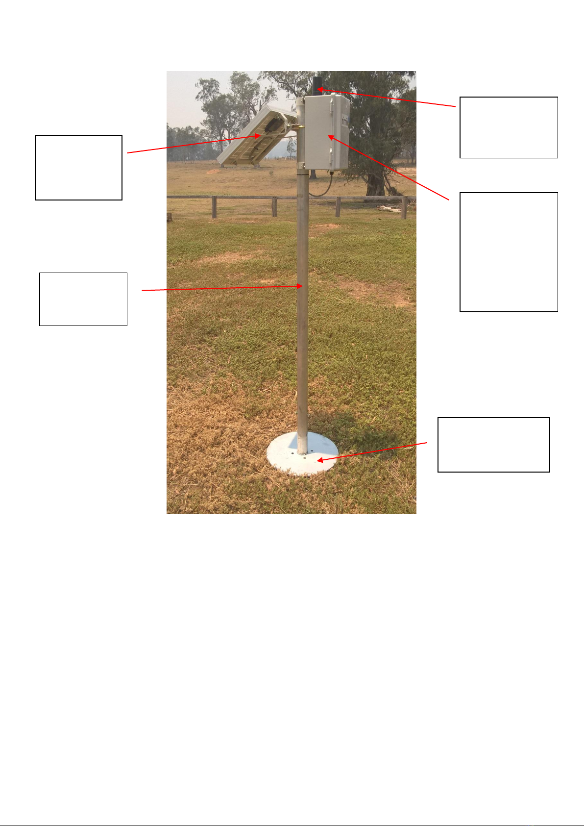
The DN300 unit has been designed for 24 hour operation at remote unpowered sites where solar
recharge is necessary. However, it can operate solely on mains power at mains powered sites with
or without a backup battery. Battery only operation is also possible for short term logger placement.
The battery life in this situation depends on the requirements of the connected sensors and use of
ultra low power mode with the DN300 Unit.
Where a solar panel is fitted the solar charger regulates the input voltage to approximately 18V DC
to capture the maximum current output from the panel. At mains powers sites where solar recharge
is not required, an 18V DC plug pack is the preferred option.
Where fitted, backup batteries are specified as 12V SLA (AGM or GEL type). The standard enclosure
can accept a number of different capacities i.e. 3AH, 7AH, 9AH and 12AH. The battery is generally
fitted vertically on the battery holder tray. The unit can also operate in a horizontal position. In that
case, a secondary battery plate may be required and particularly if using the 12AH capacity in order
to carry the additional weight.
Batteries and solar panel kits are rated for the duty they need to perform. Battery capacity is usually
determined by the load placed on the system by connected devices. Solar panel rating is
determined by the relationship between available sunlight and recharge requirements for the
battery. In general, where a low capacity battery is specified it will be matched with a lower rated
panel.
External relay power can be supplied via a 2 pin connector on the left side of the battery input (5).
In general the supply voltage is limited to 24 V AC/DC but in certain cases can be up to 60V DC.
Bay default, each DN Unit is configured to operate relay module on a maximum of 12V DC supplied
by the backup battery. Where external relay power is necessary to operate any equipment that
cannot be powered from the 12V DC backup battery e.g. 24V AC solenoid valves the connect board
is configured for external relay power and fitted with a 2 pin socket.
Three fuse positions are provided on the DN connect board, one each for the External Relay Power,
Battery, and Solar Panel. In case of a short circuit or reverse polarity connection, the fuse will fail. If
you unit will not start, charge or operate external relays, please check the fuses as a first step. IF
checking the battery fuse make sure that you are not running equipment manually or in a schedule
before you turn the unit of. Do not remove fuses while the DN unit is running.
Note that the Solar Panel and battery fuses are each 1A to protect the internal circuits. Do not
increase the fuse rating.
The External Relay Power fuse is rated at 5A in earlier DN connect board revisions and 7.5A in later
DN Connect board revisions. Some special purpose DN units may be rated to 10A. Please ensure
you do not insert a fuse larger than the rating listed on the connect board otherwise damage may
occur to the DN connect board in the event of inadvertent short circuit.

DN300 Operation & Maintenance Manual Revision A Page9
Input/Output Modules
There are many different modules available to suit almost all sensors, connected equipment and
communication systems.
The most common modules are digital and analogue input. Rimik can supply input modules with
three operating voltages 3.3V, 5V and 12V and analogue inputs with 0-5V, 0-10V, 0-20mA and 4-
20mA. Other voltage and current ranges are possible on request.
Digital outputs are available in the same voltage format or can operate on external supply such as
24V AC/DC using external relay power (5). The format for output can be simple output, pulsed
output, series switched relay, 2 wire and 3 wire pulsed relay. These are usually rated at 5A but
specialised switching modules are also available e.g. 10A.
Specialised control modules are also available for position control systems with other applications
under constant development.
Communication modules are available for RS232, RS485 and SDI-12. RS485 is used in some
proprietary protocols but more generally with industry standards such as ModBus.
Where the system is provided for a standard application or the client has specified the configuration
the DN300 unit may be supplied preconfigured. Where that is not the case, modules can be easily
fitted but some care must be taken to ensure there are mounted correctly (not offset) and that the
port is configured before connecting and operating external devices. Configuration of channels and
their associated ports is carried out with the Configuration Software Tool.
Modules are tightly fitted and in the event that they need to be replaced or reconfigured they can be
difficult to remove, particularly when there are several fitting on the connect board. Rimik can
provide a module removal tool for technicians to make this task easier. Please note to power down
the unit before attempting repairs or module changes.
Starting up and powering down the DN300
Starting the unit is a two-step process. A small power switch is located in the upper left of the
connect board (see Figure 2). To power up the system the switch must be moved to down position,
next press and hold the momentary RED start button to the right of the switch until LEDs flash on
the board. The start button only needs to be held for about 1 second for the unit to start. The
function of this button is to momentarily override the 5V operating circuit and allow the unit to
start. In operation the DN300 protects the battery capacity by powering down on low voltage
(9.5V). It does so by automatically breaking the 5V operating circuit.
To power down the unit simply move the switch to the up position. The unit will power down a
short time after the switch is moved due to built-in capacitance. The small delay allows the unit to
perform shut down functions. Powering down the unit is recommended whenever an operator
wishes to connect and disconnect devices and is absolutely necessary if changing modules.

DN300 Operation & Maintenance Manual Revision A Page10
Connecting to the DN300
Standalone or networked telemetry systems can be accessed online, however it is often more
convenient for technicians to connect directly to a field unit with a laptop to make changes, upgrade
firmware or investigate local issues. For non telemetry systems (independent field loggers), direct
connection is essential.
Rimik provide a software interface to enable local communication with the DN Units. This software
incorporates a number of functions that were previously handled by separate software programs.
To use the Rimik software interface the software must be installed on a laptop or PC. In addition the
technician will require a USB C to USB Mini communication cable. Plug the USB C into the laptop and
the USB Min into the socket on the module panel (see Figure 2, #1). You do not need to shut the
DN200 down. In addition the DN200 unit must be running in order to communicate with it.
DN Configuration Tool (DN CT)
The latest version of the DN Configuration Tool can be downloaded from www.rimik.com/resources.
This software interface allows users to communicate directly with a DN Unit via a USB C to USB Mini
cable. Direct communication enables the user to interact with the unit locally via a Windows based
laptop or tablet. The configuration tool allows the User to read and write to general settings, view
readings and download logged data. If logged in as a Technician other functions are available
including the following:
Update firmware locally
Read and configure channels
Read and configure modules
Reset the DN200 to factory default
Send and receive SDI-12 commands
Alter the security pin number
User a terminal window
Read and alter Telemetry module settings
Other functions will be incorporated over time including a Direct ModBus Terminal Window and
other pass through communication windows.
As new features are added, please ensure you stay up to date by checking our website for changes
to the current revision number and or changes to the name of the Tool.
Connection
Connect to the DN300 using the USB port provided using a USB C to USB Mini cable.
For information on how to interact locally with the DN300 please read the DN Configuration User
manual.
Firrmware Update
From time to time changes occur to operating systems. A version update file may contain fixes for
your device or include new functions at your request. All DN200 units except satellite models should

DN300 Operation & Maintenance Manual Revision A Page11
be capable of remote update over IP. If you are required to undertake a firmware update, you will
be supplied with a XXX.hex file from Rimik. Save it in a location that can be accessed by DN CT.
The DN CT software has an embedded Firmware Update tool. Click on “Firmware Update” in the
menu list to enter this function. You will need to read the DN Configuration Tool Technician Manual
for information on how to do this.
If you experience any issues with this process please contact Rimik or your local Distributer/Reseller.

DN300 Operation & Maintenance Manual Revision A Page12
Maintenance
A DataNode System can be accessed as often as required using any of the connection methods. The
most effective for daily checks are SMS, RF Telemetry and Modem communication. Being a remote
system, users would only access the system directly when on-site with the unit for other
maintenance purposes.
The system can be fully interrogated daily when connected to our online services via 4G (Cat M1
NBIot), LoRaWAN or Satellite. Direct communication is available to the 4G modem if necessary for
telecommunication network validation and modem interrogation. If RT Telemetry is fitted outside of
an IP connection it is possible to talk to remote units via a radio modem. In other cases direct
connection via serial cable allows the Technician to download data, investigate issues and alter
setting on site.
Note that all local capability is available via the remote connection provided the unit is online.
Via On-Site Maintenance
Regardless of other condition indicators, users should undertake periodic maintenance in order to
keep their system in peak condition. On-site maintenance is recommended at least every quarter.
Parameter
Maintenance Requirement
Mounting
Check to make sure all equipment is intact and firmly connected.
Movement in any piece of equipment should be eliminated.
Cable connections
Make sure that connections to the base of the enclosure are firm and
locked.
Gland Entries
Makes sure that these are tight and the cable will not slide.
Vents (if fitted)
Vents (when fitted) have an expanded foam insert inserted to stop
ingress of insects. Any ingress by insects should be eliminated.
Solar Panel
Be prepared to clean the panel. Regardless of deterrents, birds do try
to roost on or near the panel. The "glass" surface can be easily
cleaned using a cloth and clean water. We do not recommend the use
of any cleaning agents and certainly no fuel based solvents.
Connected Equipment
Check all cables and connected instruments to make sure nothing has
been dislodged.
Enclosure
On opening the enclosure a user should check the door seal to ensure
it is fully intact. Make sure there is no moisture inside. Check the
enclosure thoroughly to make sure no insects have entered or found
permanent lodging. If they have try to locate the entry point and seal
it. If necessary place a dry deterrent in the bottom of the enclosure to
stop future infestation. If surface sprays are used, do not spray them
onto any exposed connectors.
System On
Check DataNode indicator LED's
Status, Supply, Battery, RT Comms and Signal Strength, Charging and
charging fault.
Power and charging lights generally flash once per 5 seconds, and RT
flash when awake and transmitting.
Battery Voltage
This will depend on when the system is checked.
As the solar panel will only commence charging the battery when
enough sunlight is present, a correctly operating system should be
flashing green during the morning and reach fully charged state during

DN300 Operation & Maintenance Manual Revision A Page13
the afternoon. If available, a multimeter can be used to check the
battery voltage and compare this with the power flashing sequence.
Modem Function
If fitted the modem power and data LEDs will indicate according to
the table found in the section "Internet Communication With Bigpond
Mobile Internet Plan". In areas of good signal strength the Power LED
will remain ON. The Data LED will only switch on when it is connected
to the network or data is being transmitted to the modem from the
DataNode.
Direct Connection
Where necessary, directly connect to the DataNode via a laptop with a
Rimik serial cable and Interface software. Once connected all system
parameters can be checked and stored data downloaded.
The following on-site interface checks are not essential but are
recommended:
Date and Time (adjust if necessary)
Calibrated Stored Readings
Calibrated Readings
A user wishing to check calibrated readings against actual results must
have a means of measuring all parameters with a secondary device.
This might be a manual gauge reading for level or pressure,
alternatively a hand held device for temperature, RH etc.
Calibrated readings that deviate from the comparison device will need
to be investigated.
Logged Data
Download and check through logged data for evidence of correct
function. Note that the following appended notes may be found at
the end of a line according to the appropriate time period:
Network Time Update - Once per day at 9.00am
Successful upload - Once per hour
Alerts - Battery Voltage below 10.5 Volts

DN300 Operation & Maintenance Manual Revision A Page14
Troubleshooting
Problem
Likely cause(s)
Potential solutions
Monday Status
update not
delivered
No modem or network down
System Off
SMS Status update to modem and wait for
response.
See below.
System Off
Extreme weather
(Local lightening strike raises
ground plane voltage)
Battery failure
(Replace battery)
Not Charging
Check the battery voltage with a
multimeter prior to restarting the
DataNode.
If the battery voltage is below 9.5 volts
the system will not start and continue to
operate. Change the battery if that is the
case.
Restart the DataNode and make sure the
power and log LED's are flashing correctly.
Check the battery voltage with a
multimeter to make sure it is holding
voltage.
If it is daylight the panel should be
charging the battery. If this is the case,
the voltage should slowly increase over
time.
If possible download and analyse to late
series of logged data to determine how
the problem arose
Not Charging
Dirty panel
Wiring connections loose or
corroded
Clean panel and check that DataNode
system is charging correctly
Chek the solar panel voltage across the 2
pin plug when connected and when
disconnected from the DN300. It should
read approximately 20 volts across the
plug when disconnected and about 18V
when connected and in good light. Check
that all external and internal connections
are firmly seated and clean.
Sensor not reading
correctly
Shift in zero value reading
Individual senor has become
unstable
Check original zero value reading
(pressure transducer). Remove sensor
and check zero reading against stored
value.
Contact Rimik for repair or replacement if
problems persist
Alerts not
transmitted
System Off
Alerts not set up correctly
Attempt contact via RF or SMS, if no
response a site visit is required.
Check that alerts are turned on.
Move the sensor to an alert condition to
prove correct function (e.g. low level).
One LED not
flashing
Loose internal connection or
LED has blown
Contact Rimik for advice or repair

DN300 Operation & Maintenance Manual Revision A Page15
Notes:
Table of contents
Other Rimik Measuring Instrument manuals