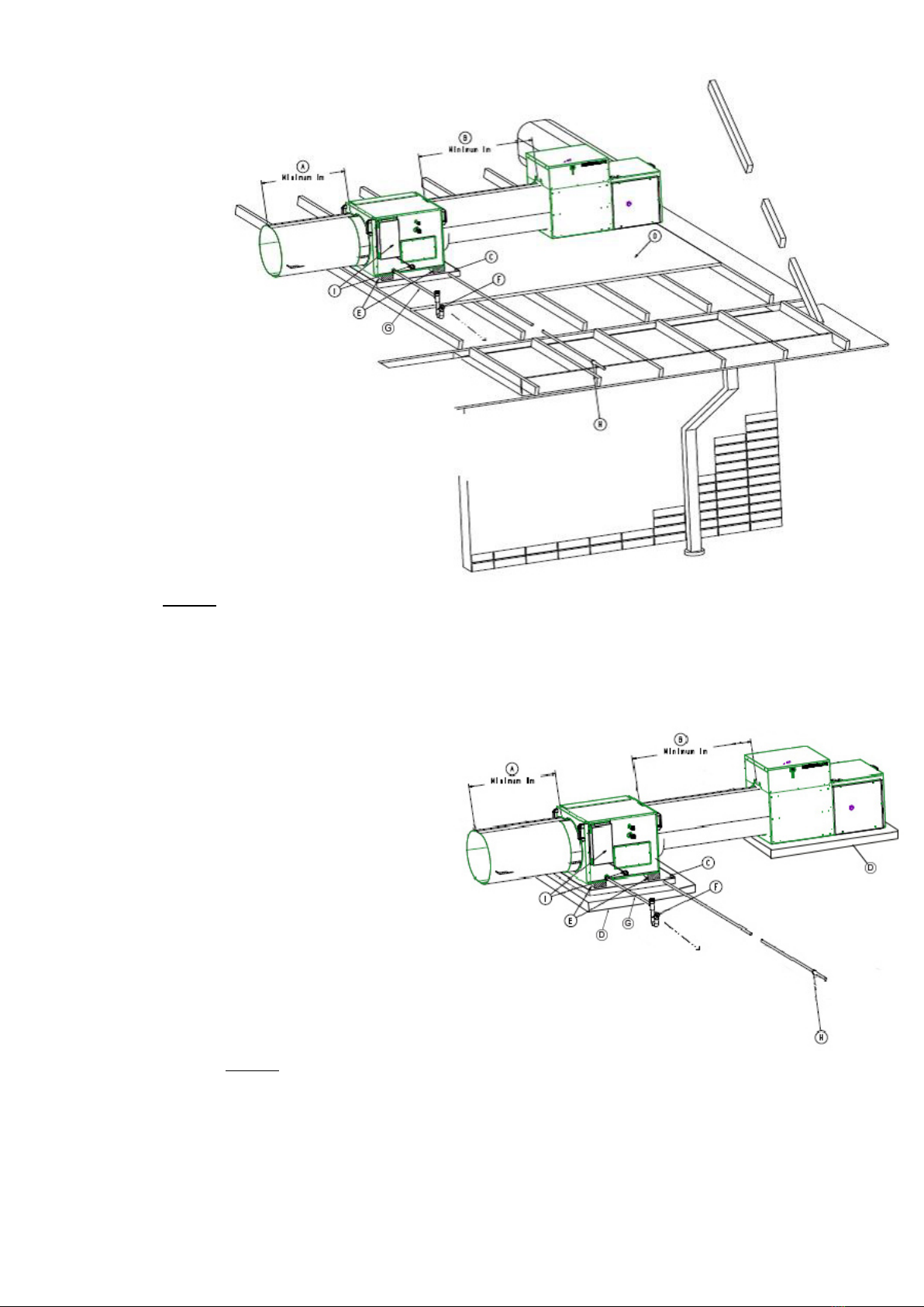
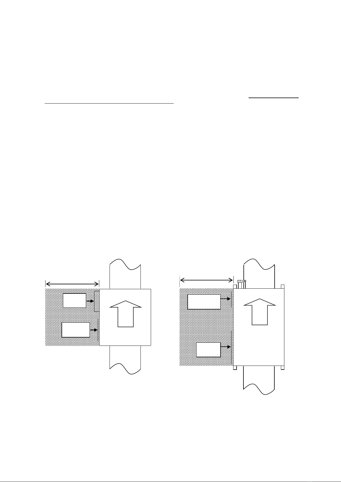
A. Ensure 1m minimum, or preferably 2½ times
the duct diameter, STRAIGHT duct length
before any take-offs occur
B. Ensure 1m minimum STRAIGHT duct between the
Gas Ducted Heater and ICE coil unit
C. Safety Drain Tray (field supplied), independently
drained
D. Working Platform (field supplied)
E. Unit Mounts (field supplied) to be fitted under unit
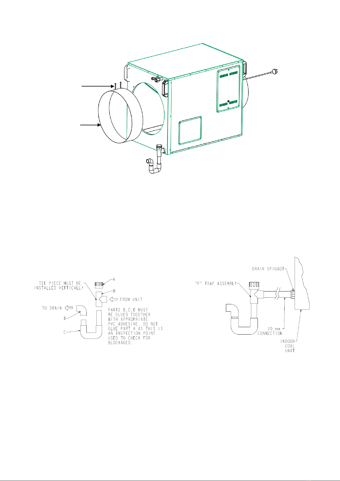
F. P Trap Assembly (supplied) on primary condensate
drain – fit as close as possible to unit
G. Condensate drain pipe to be pitched down and to be
terminated in an approved manner as specified by
local codes
H. Terminate the Safety Drain Tray in a position so as not
to cause a nuisance, but where the home owner can
see if water is dripping. Instruct owner to contact
Installer or Brivis if Safety Drain Tray outlet drips water
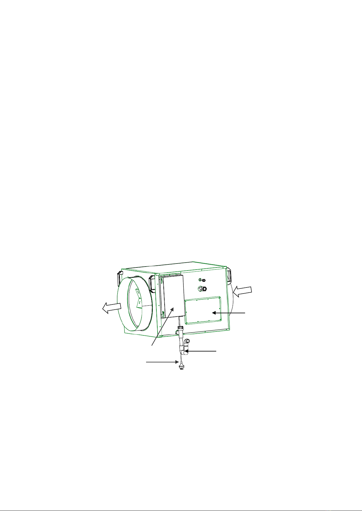
I. Electric box with standard 10 A power plug
•Run 2 core shielded communication cable from
indoor coil electric box
(Terminals Q, P) to the outdoor unit (S1,S2).
•Run 24VAC from the heater into the indoor coil
electric box (Terminals A1, A2)
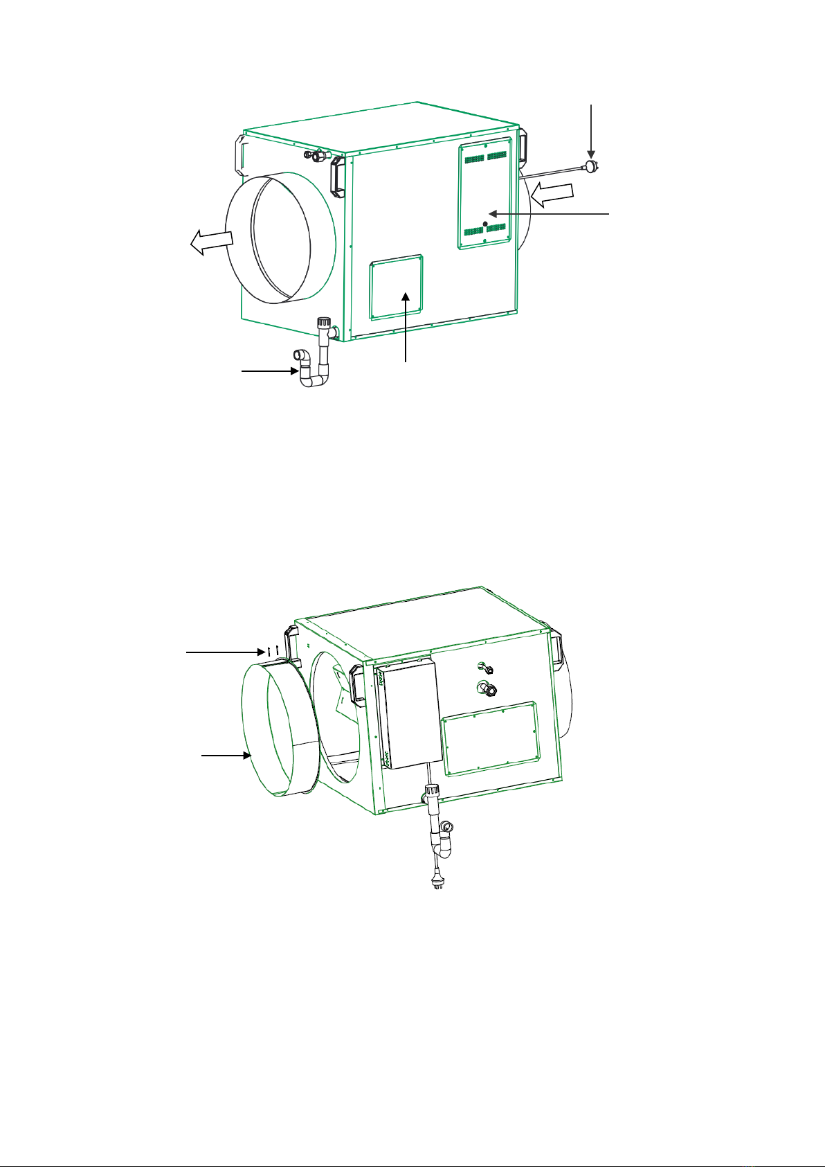
3.0 TYPICAL INSTALLATION
Fig. 6 - Typical Indoor Unit Installation
Fig. 7 - Typical Under Floor Installation
A. Ensure 1m minimum, or preferably 2½ times the
duct diameter, STRAIGHT duct length before any
take-offs occur
B. Ensure 1m minimum STRAIGHT duct between the
Gas Ducted Heater and ICE coil unit
C. Safety Drain Tray (field supplied), independently
drained
D. Working Platform (concrete slab)
E. Unit Mounts (field supplied) to be fitted under unit
F. P Trap Assembly (supplied) on primary
condensate drain – fit as close as possible to unit
G. Condensate drain pipe to be pitched down and to
be terminated in an approved manner as specified
by local codes
H. Terminate the Safety Drain Tray in a position so
as not to cause a nuisance, but where the home
owner can see if water is dripping. Instruct owner
to contact Installer or Brivis if Safety Drain Tray
outlet drips water
I. Electric box with standard 10 A power plug
•Run 2 core shielded communication cable from indoor coil electric box
(Terminals Q, P) to the outdoor unit (S1,S2).
•Run 24VAC from the heater into the indoor coil electric box (Terminals A1, A2)
IMPORTANT NOTE
1. Ensure unit is sitting on something that is ‘weather/waterproof’
2. Make sure there is adequate ventilation to help prevent condensation
3. Ensure the P-Trap and drain are working effectively
4. Always mount the coil on (field supplied) supports to create an air gap to prevent moisture/condensation
5. Always mount coil over safety tray