Rioned CityJet User manual
CityJet
user manual

2
Operating and maintenance manual
Identification number: vo . . . . .
Serial number: . . . . . . . . . . . . .
Type CityJet
Year of manufacture: . . . .
Manufacturer:
Rioned
Centaurusweg 45
5015 TC Tilburg
P.O. Box 5070
NL-5004 EB Tilburg
Tel. no.: +31 13-5479100
E-mail: [email protected]
Internet: www.rioned.com
For information about adjustments, maintenance or repairs not contained in this user manual, contact
Rioned.
Original user manual
Publication date: 1/2/19
Version: 21
All rights reserved. No part of this publication may be reproduced and/or made public by means of
printing, photocopying, microfilm or any other means whatsoever without the prior written permission of
Rioned.
Rioned reserves the right to make changes to parts at any time, without providing prior or direct
notification to the buyer. The content of this user manual may also be changed without prior notification.

3
Preface
This user manual is intended for the professional user. It is intended to enable the user to
operate the machine and must always be kept with the machine.
The photographs and drawings in the manual are intended to support the text.
In this user manual you will first find an introduction that describes, among other things, the
intended purpose of the machine. Then there is an explanation of how the machine is
constructed and how it works in general. This is followed by an overview of the most important
safety aspects.
Then the best way to start up and operate the machine is explained. The standard functions and
additional functions are described separately. The information in the Maintenance section
allows you to perform simple maintenance work yourself. Troubleshooting tips to help you
correct minor malfunctions yourself are also provided.
Finally, at the end of this user manual you will find an index to help you quickly find information
and a number of annexes containing, among other things, Rioned's contact details.

4

5
Table of contents
Preface ......................................................... 3
Table of contents......................................... 5
1 Introduction ....................................... 7
2 Description and principle of
operation.............................................9
2.1 Introduction...................................................................9
2.2 Machine.........................................................................9
2.2.1 Design and principle of operation................................9
2.2.2 Symbols on pressure gauge, pressure regulator
and valve controls ........................................................15
2.2.3 Accessories...................................................................15
2.3 eControl+..................................................................... 16
2.3.1 Design and principle of operation.............................. 16
2.3.2 eControl+......................................................................17
2.3.3 Lightbar.........................................................................18
2.3.4 Navigation bullets ........................................................18
2.3.5 Functions and symbols............................................... 22
2.3.6 Tachometer.................................................................. 23
2.4 Riomote control (option)............................................ 23
2.4.1 Introduction................................................................. 23
2.4.2 Preparation for use...................................................... 24
2.4.3 Replacing the battery................................................... 26
2.4.4 5-channel Riomote control.......................................... 27
2.4.5 7-channel Riomote control.......................................... 28
2.4.6 9-channel Riomote control .........................................29
3 Safety..................................................31
3.1 Introduction..................................................................31
3.2 General danger symbol ................................................31
3.3 Working safely ..............................................................31
3.4 Dangers of non-compliance with safety
instructions ..................................................................31
3.5 Use only by authorized personnel .............................. 32
3.6 Bystanders ................................................................... 32
3.7 Restrictions on use...................................................... 32
3.8 Thunderstorm ............................................................. 32
3.9 Spraying....................................................................... 32
3.10 Spray break ...................................................................33
3.11 Sewer gases ..................................................................33
3.12 Water tank ....................................................................33
3.13 Emergency stop............................................................33
3.14 Levers and valves .........................................................33
3.15 Personal protective equipment....................................33
3.16 Water discharge........................................................... 34
3.17 Other machine safety provisions................................ 34
3.17.1 Introduction................................................................. 34
3.17.2 Pressure regulator ....................................................... 34
3.17.3 Protective covers ......................................................... 34
3.18 Safety sticker.................................................................35
4 Operation: standard functions........ 37
4.1 Introduction..................................................................37
4.2 Checks before departure ..............................................37
4.3 Preparations at the workplace .................................... 38
4.3.1 Preparing the vehicle ...................................................38
4.3.2 Before starting..............................................................38
4.3.3 Workstations ................................................................39
4.4 Starting the engine...................................................... 40
4.4.1 Starting the engine with the eControl+...................... 40
4.4.2 Starting the engine with the Riomote control............ 42
4.4.3 Unblocking a sewer......................................................43
4.4.4 Spray nozzle warning...................................................43
4.4.5 Preparations for spraying ............................................43
4.4.6 Starting spraying......................................................... 44
4.4.7 Stopping spraying ........................................................45
4.4.8 Handling the high pressure hose............................... 46
4.5 Cleaning a wall, terrace or floor.................................. 46
4.5.1 Warnings for spray gun .............................................. 46
4.5.2 Preparations for spraying ........................................... 46
4.5.3 Pressurizing the system...............................................47
4.5.4 Starting spraying..........................................................47
4.5.5 Depressurizing the system..........................................47
4.6 Ending the work .......................................................... 48
4.6.1 Cleaning up, securing and draining ........................... 48
4.6.2 Additional steps during freezing temperatures ......... 48
5 Operation: extra functions ...............51
5.1 Introduction ................................................................. 51
5.2 Pulsator ........................................................................ 51
5.2.1 Introduction ................................................................. 51
5.2.2 Manual operation pulsator.......................................... 51
5.2.3 Starting the pulsator with the eControl+ .................... 51
5.2.4 Stopping the pulsator with the eControl+ ..................52
5.2.5 Setting the speed with the eControl+ when the
pulsator is switched on................................................ 53
5.2.6 Starting the pulsator with the Riomote control ..........54
5.2.7 Stopping the pulsator with the Riomote control ........54
5.3 Electric swivel arm latch .............................................. 55
5.4 Reel...............................................................................56
5.4.1 Safety ............................................................................56
5.4.2 Hydraulically reeling high pressure hose in/out.........56
5.4.3 Manually reeling high pressure hose out.................... 57
5.4.4 Hose guide ................................................................... 57
5.4.5 Reeling high pressure hose in/out with the
eControl+ .....................................................................58
5.4.6 Manually reeling out high pressure hose
controlled by eControl+ .............................................. 60
5.4.7 Reeling in/out with the Riomote control ....................61
5.5 Hose meter counter eControl+ .................................. 62
5.5.1 Introduction ................................................................ 62
5.5.2 Activating the eControl+............................................. 62
5.5.3 Switching the hose counter on and off ...................... 62
5.5.4 Resetting hose counter to 0 metres............................63
5.5.5 Switching between ‘metres’ and ‘feet’ ........................63
5.6 Electronic water level control ..................................... 64
5.7 Suction venturi............................................................ 64
5.8 Eco mode eControl+....................................................65
5.8.1 Introduction .................................................................65
5.8.2 Switching eco mode on and off...................................65
5.8.3 ECO Start/Stop ............................................................67
5.8.4 ECO Stop......................................................................67
5.9 Management function eControl+............................... 68

6
6 Maintenance......................................71
6.1 Safety instructions........................................................71
6.2 Making changes to the machine..................................71
6.3 Maintenance schedule .................................................71
6.4 Removal/installation of protective covers...................73
6.5 Maintenance before the work ......................................73
6.5.1 Check oil levels .............................................................73
6.5.2 Clean water filter.......................................................... 74
6.5.3 Check high pressure hose and other hoses ............... 74
6.5.4 Maintenance of remote control.................................. 74
6.6 Weekly maintenance ................................................... 74
6.7 Maintenance every 50 hours of operation.................. 74
6.8 Maintenance every 250 hours of operation or
at least once every six months.....................................75
6.8.1 Lubricate moving parts ................................................75
6.8.2 Clean pressure regulator..............................................75
6.9 Maintenance every 1000 hours of operation or
at least once a year.......................................................75
6.9.1 Change hydraulic oil.....................................................75
6.9.2 Clean suction valves of high pressure pump ..............75
6.9.3 Clean pressure valves of high pressure pump........... 76
6.9.4 Major scheduled maintenance ................................... 76
7 Malfunctions .....................................77
7.1 Fault messages, eControl+..........................................77
7.1.1 Emergency stop ...........................................................77
7.1.2 Engine temperature too high ......................................77
7.1.3 Heat exchanger temperature too high ........................77
7.1.4 Hydraulic oil temperature too high.............................78
7.1.5 Hydraulic oil level too low ...........................................78
7.1.6 Coolant level too low ...................................................79
7.1.7 Battery voltage too low ................................................79
7.1.8 Water level too low.......................................................79
7.1.9 Water level too high .................................................... 80
7.1.10 Troubleshooting........................................................... 81
8 Index ................................................. 87
9 Attachments ..................................... 91
Annex 1 EC declaration of conformity......................................... 92
Annex 2 Type plate .......................................................................93
Annex 3 Dimensions ................................................................... 94
Annex 4 Technical specifications.................................................95
Annex 5 Contact details................................................................97
INTRODUCTION
7
1 Introduction
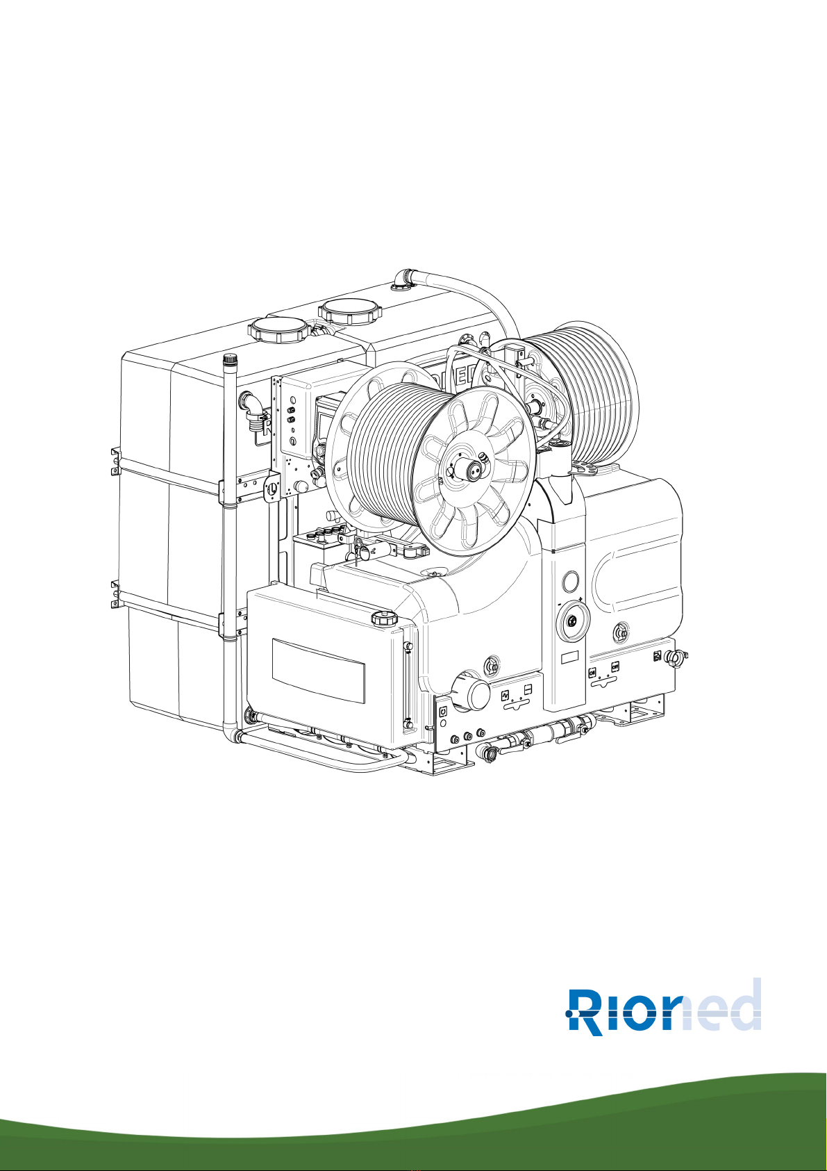
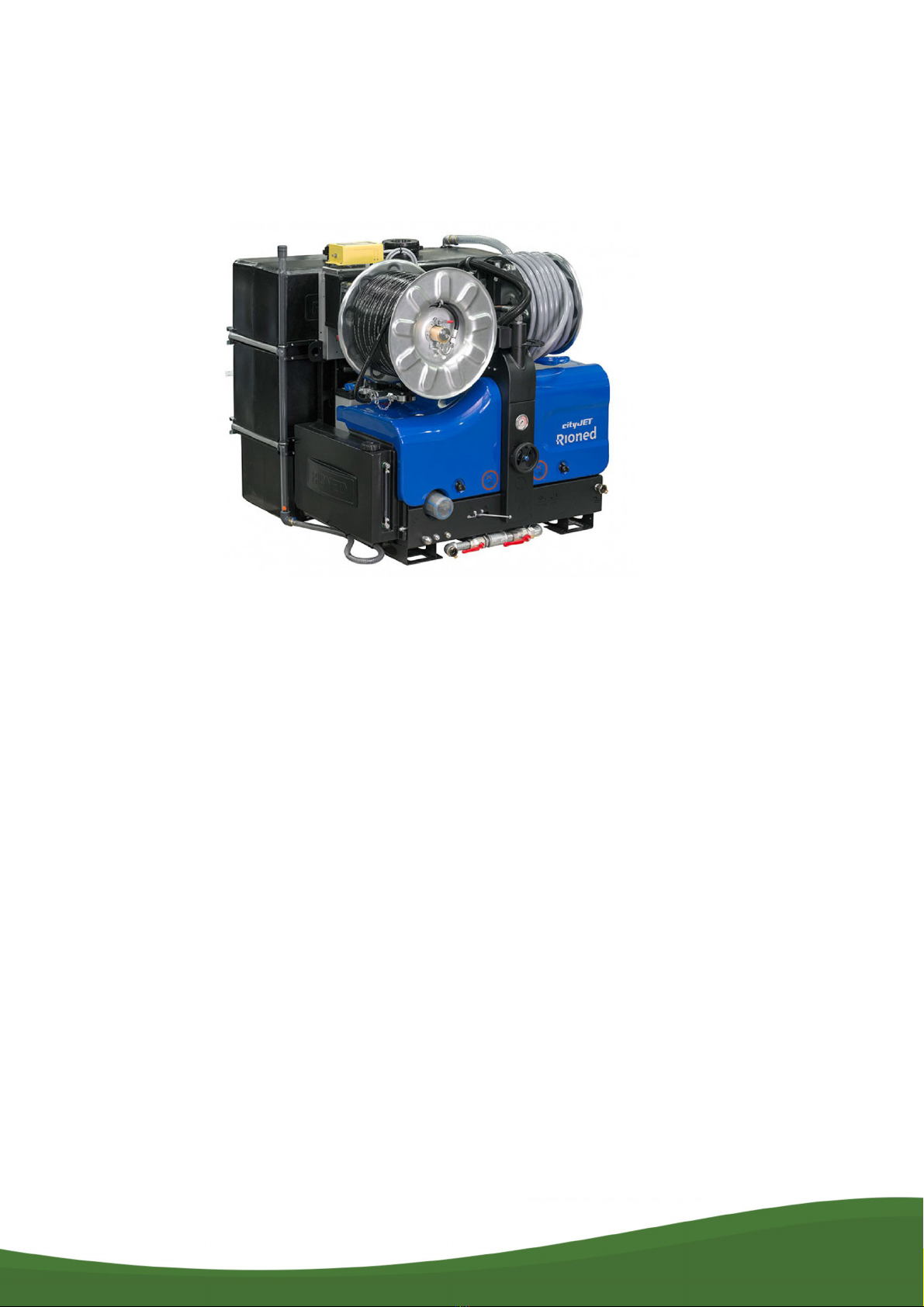
Congratulations on the purchase of the
CityJet
! The
CityJet
is intended for unblocking sewers and cleaning
walls, terraces and floors. With correct use, this machine will serve you well for years to come.
Read this user manual carefully before putting the machine in service, and always use the machine in
accordance with the instructions. If problems occur, consult Rioned.
This user manual contains all the information about operation and maintenance. If the machine is set up
and operated correctly and regularly maintained, we provide the warranty specified in the general terms
and conditions of delivery. The warranty is void and your safety and that of people in the vicinity cannot
be guaranteed if the operating and maintenance instructions are not followed or are not followed correctly.
The following requirements must be met when working with the machine:
Use in enclosed spaces:
> When working in an enclosed space, the space must be well ventilated.
> Make sure the combustion gases are properly discharged. Prevent CO poisoning!
Spray site:
ALWAYS follow the instructions below for the spray site:
> Demarcate the site clearly. The minimum distance between the spray site and the demarcation is six
metres.
> Remove anything within the demarcation that is not firmly anchored.
> NEVER spray from an unstable location. Examples: ladder, boat, or hanging scaffolding.
> If it is necessary to use artificial lighting, ALWAYS use waterproof light fixtures.

INTRODUCTION
8

DESCRIPTION AND PRINCIPLE OF OPERATION
9
2 Description and principle of operation
2.1 Introduction
In this chapter we first briefly describe the operation, the main components and the symbols used for the
machine and the accompanying accessories. You will then find a description of the machine's control
units in the ‘
eControl+
’ and ‘
Riomote control
’ sections.
2.2 Machine
2.2.1 Design and principle of operation
The engine drives the high-pressure pump via a V-belt The high pressure pump draws water from the
water tank via the water filter and pressurizes it. The water then exits the machine at high pressure via the
high pressure hose on the reel.
The machine consists of the following parts:
1. High pressure hose on reel
2. Filling reel
3. Securing end of filling hose
4. Pump cover
5. Engine cover
6. Filling valve, water tank
7. 12 V connection
8. Spray nozzles on holders
9. Battery
10. Water tank
11. Supply valve, filling reel
12. eControl+
13. Hose guide
14. High pressure valve
15. Navigation knob, eControl
16. Button, emergency stop
17. Lever, control slider, hydraulic reel
control
18. Hose holder
19. Fuel tank
20. Locks, covers
21. Drain valve, water filter
22. Connection, drain hose
23. Reel latch
24. Latch, swivel arm
25. Pressure gauge
26. Pressure regulator
27. Water filter
28. Supply valve, water filter
29. Indicator, water level
30. High pressure pump
31. Oil tank, hydraulic system
32. Engine
33. Receiver, Riomote control (option)
34. Battery charger, Riomote control (option)
35. Pulsator on/off


DESCRIPTION AND PRINCIPLE OF OPERATION
13
The following is a brief explanation of parts from the illustrations above that are not discussed further in
the manual.
Securing end of filling hose (3)
The end of the filling hose is attached to this connection.
Pump cover (4)
Removing this cover will make the pump, battery and oil tank accessible for maintenance and service.
Engine cover (5)
Removing this cover will make the engine accessible for maintenance and service.
12V connection (7)
The 12 volt connection is used to connect accessories, such as a work light.
Spray nozzles on holders (8)
Screw the spray nozzles onto the nozzle holders.
Battery (9)
The battery supplies the machine with power.
Supply valve, filling reel (11)
Open this valve when the water tanks are filled through the filling hose.
High pressure valve (14)
This valve regulates the supply of water to the high pressure hose. If the Riomote control (option) is
installed, the high pressure valve is always open. The water supply is then controlled by the valve on the
actuator. The high pressure valve acts as a safety valve in an emergency: this allows you to immediately
interrupt the supply of water to the high pressure hose.
Locks, covers (20)
The pump and engine cover are held in place with these locks.
Connection, drain hose (22)
Connect the drain hose here and place the end of the hose outside the vehicle when you want to empty
the water tanks. Then the vehicle will remain dry inside.
Reel latch (23)
This latch prevents the reel from turning. It is operated by twisting the wings.
Latch, swivel arm (24)
The latch of the swivel arm holds the swivel arm in place. There are four different positions:
> In the first position, the swivel arm is completely in the machine. This position is intended for driving
the vehicle. In the other positions the vehicle must NOT be driven.

DESCRIPTION AND PRINCIPLE OF OPERATION
14
> The other three positions are intended for positioning the high pressure hose as close as possible to
the correct working direction. This ensures that the high pressure hose rolls off the reel smoothly.
It is operated as follows:
1. Press the button on the swivel arm latch:
Swivel arm latch releases.
2. Swing the swivel arm to the desired position.
3. Release the button on the swivel arm latch: Swivel arm latch latches into the next hole it reaches.
Indicator, water level (29)
This indicates the water level in the water tank.
DESCRIPTION AND PRINCIPLE OF OPERATION
15
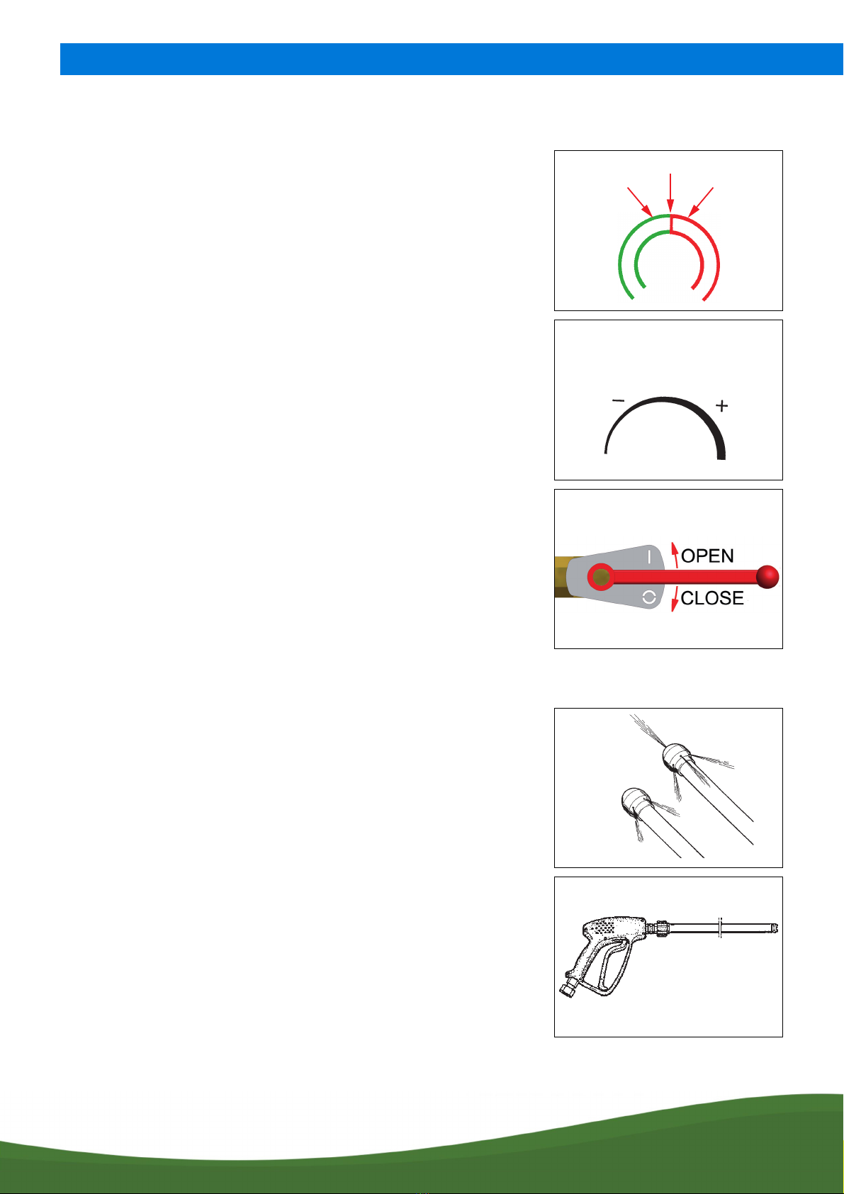
2.2.2 Symbols on pressure gauge, pressure regulator and valve controls
2.2.3 Accessories
Pressure gauge (25)
The maximum operating pressure is indicated on a sticker near the pressure
gauge.
Reduce the operating pressure with the handwheel of the pressure regulator until
the indicator of the pressure gauge is halfway between 0and the maximum
operating pressure.
Pressure regulator (26)
Operation of high pressure valve (14)
Move the lever up to open the high pressure valve. Move the lever down to close
the high pressure valve.
The following are included as standard with the machine:
1. Two nozzles for unblocking sewers: ‘Open nozzle’ and ‘Blind nozzle’, which
are fitted on the end of the high pressure hose.
2. One spray gun with lance for cleaning façades, terraces and floors.
The spray gun is attached to the end of the high pressure hose using the
open-end spanners. These open-end spanners are also supplied as standard.
Operating
range
Danger zone
Maximum allowable pressure
Less pressure More pressure
Spray nozzle, open
Spray nozzle, blind
Spray gun with lance

DESCRIPTION AND PRINCIPLE OF OPERATION
16
2.3 eControl+
2.3.1 Design and principle of operation
With the eControl+ you can operate the machine via the navigation knob. You can also use the eControl+
to control a number of options. The status is always shown on the display of the eControl+.
3. Two open-end spanners for tightening and loosening the spray gun.
4. This user manual
5. Engine documentation
6. One suction hose with strainer.
7. Attachment: high pressure pump
8. Attachment: exploded view drawings and diagrams.
Open-end spanners
DESCRIPTION AND PRINCIPLE OF OPERATION
17
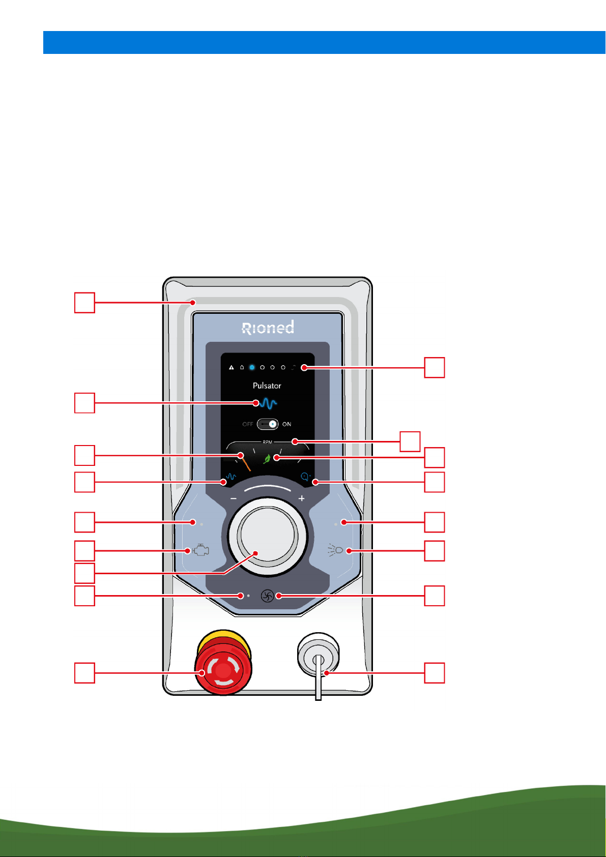
2.3.2 eControl+
The following illustrations and text provide a more detailed description of the various parts of the
eControl+.
36. Lightbar
37. Navigation bullets
38. Function icons
39. Tachometer
40. Tachometer pointer
41. Iconeco mode
42. Pulsator icon
43. High pressure reel icon
44. Motor LED
45. Engine on/off button
46. High pressure LED
47. High pressure on/off button
48. Not applicable
49. Not applicable
50. Navigation knob
51. Button, emergency stop
52. Key (3 positions: eControl+ off, manual
operation and Riomote control (option))
36
38
37
39
40
42
44
45
48
51
41
43
46
47
49
52
50
DESCRIPTION AND PRINCIPLE OF OPERATION
18
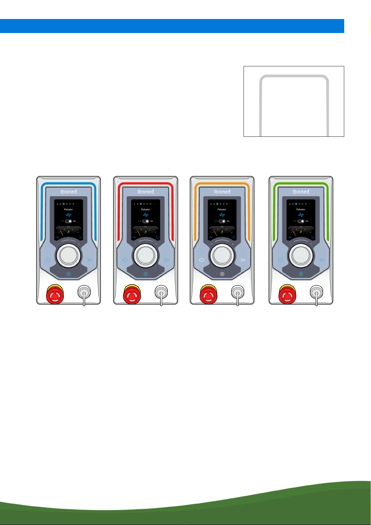
2.3.3 Lightbar
In the following cases it changes to one of these four colours:
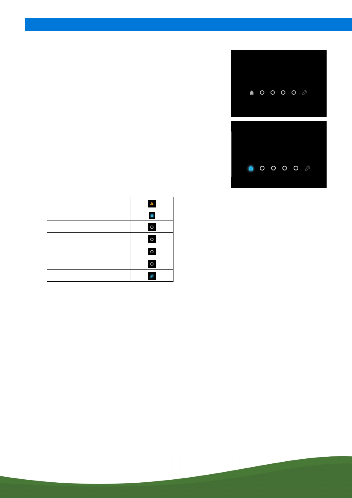
2.3.4 Navigation bullets
The navigation bullets show how many menus are available. They are normally shown in one of two states:
The navigation bullets represent the following, from left to right:
The lightbar around the display is switched off (always grey) by default:
BLUE RED ORANGE GREEN
The Riomote control
is set on the
eControl+
There is a fault The diesel engine is
being preheated or
the high-pressure
pump is running dry
or the oil level is too
low
Spraying has been
stopped by the ECO
Start/Stop or the
ECO Stop
DESCRIPTION AND PRINCIPLE OF OPERATION
19
Inactive (grey):
Active (blue):
Depending on where you are in the menu, one navigation bullet is visible or – in
a pop-up – all navigation bullets disappear.
Fault
Home
Pulsator
Reel
Hose counter
Eco mode
Management

DESCRIPTION AND PRINCIPLE OF OPERATION
20
Fault
The first navigation bullet (Fault ) is only visible when a fault message is suppressed, for example ‘too
little water in the water tank (run dry)’. Only then can you navigate to this bullet. In other cases, the bullet
is hidden.
Fault (inactive, grey):
Fault (active, blue):
Table of contents
Other Rioned Pressure Washer manuals


