EVGA nForce 750i SLI User manual
1-1
Getting Started
Getting Started
Chapter1
Thankyouforchoosingthe750i(V1.X) ATXmainboard.
ThemainboardisbasedonNVIDIA nForce750i SLI
(C72P)&430i(MCP51)chipsetsforoptimal system
efficiency.DesignedtofittheadvancedIntel CoreTM2
Extreme,CoreTM2Quad,CoreTM2Duo, Pentium Dual-
Coreand Celeron processors,themainboarddelivers
ahigh performanceand professionaldesktopplatform
solution.
PDFcreated withpdfFactoryProtrialversion www.pdffactory.com
750iMainboard
1-2
MainboardSpecifications
Processor
-Intel CoreTM2Extreme,CoreTM2Quad,CoreTM2Duo,Pentium
Dual-Coreand Celeron processorsin theLGA775 package
-SupportsIntel SpeedStepTechnology(EIST)
-SupportsIntel Hyper-Threading Technology(HT)
FSB
-400/533/800/ 1066/ 1333/1800 (OC)MHz
Chipset
-NorthBridge:NVIDIA nForce750iSLIchipset(C72P)
-SouthBridge:NVIDIA nForce430ichipset(MCP51)
Memory
-DDR2533/667/ 800/1200(OC)SDRAM
-4DDR2DIMMslots(8GBMax)(240-Pin/ 1.8V)
LAN
-Supports10/100/1000 FastEthernetbyRealtek RTL8211BL
-CompliantwithPCI2.2
-SupportsACPIPowerManagement
IEEE1394
-Chip integrated byVIA VT6308P
-Transferrateisup to400 Mb/s
Audio
-ChipintegratedbyRealtek ALC888S
-Flexible8-channelaudiowithjacksensing
-CompliantwithAzalia1.0spec
-MeetMicrosoft Windows VistaTM Premiumspec
IDE
-2IDEportsbyNVIDIA nForce430i
-SupportsfourIDEdevices
-SupportsUltraDMA33/ 66/100/ 133mode
-SupportsPIO, BusMasteroperationmode
SATA
-4SATAportsbyNVIDIA nForce430i
-SupportsfourSATAdevices
-Supportsstorageand datatransfersup to3Gb/s
-1eSATAportbyJMicron JMB363
PDFcreated withpdfFactoryProtrialversion www.pdffactory.com
1-3
Getting Started
RAID
-4SATAII portssupport RAID0/1/ 0+1/5orJBODmodebyNVIDIA
nForce430i
-1eSATAportsupportRAID0/1mode byJMicron JMB363
Floppy
-1floppyportsupports1FDDwith360KB,720KB, 1.2MB,1.44MB
and2.88MB
BackPanel
-1PS/2mouse/keyboardport
-1opticalS/PDIF-out port
-1coaxialS/PDIF-outport
-1debugLED
-1clearCMOSbutton
-1IEEE1394port
-6USB ports
-1eSATAport
-1LANjack
-6audiojacks
Connector
-1CD-in connector
-1frontpanelaudioconnector
-1serialportconnector
-1IEEE1394connector
-1USB connector
-1S/PDIF-outconnector
Slots
-2PCIexpress x16 slots
-1PCI express x1slot
-2PCIslotssupport 3.3V/ 5VPCIbusinterface
FormFactor
-ATX(30.5cmX24.5cm)
Mounting
-9mounting holes
PDFcreated withpdfFactoryProtrialversion www.pdffactory.com

750iMainboard
1-4
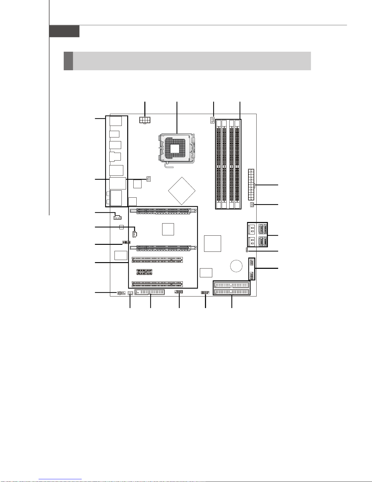
750i (V1.X) ATXMainboard
MainboardLayout
PCI1
PCI_E1
PCI_E2
PCI_E3
PCI2
IDE1
IDE2
FDD1
J1394_1
JAUD1
BATT
+
JUSB1
SYSFAN3
JCOM1
T: LINE-IN
M:LINE-OUT
B:MIC
T:RS-OUT
M:CS-OUT
B:SS-OUT
SATA3_4SYSFAN2
JPWR2
JCD1
JPWR1
CPUFAN1
SATA1_2
JFP1JFP2
T:MOUSE/
B: USBPORTS
KEYBOARD
T:LANJACK
B:USB PORTS
T:1394PORT
B: USBPORTS/ESATAPORT
JOC1
DIMM1
DIMM2
DIMM3
DIMM4
NVIDIA
C55
NVIDIA
MCP51
VIA
VT6308P
NVIDIA
NF200
FINTEK
F71882FG
REALTEK
ALC888S
JMICRON
JMB363
REALTEK
RTL8211BL SYSFAN1
CLEARCMOSBUTTON
T:OPTICALS/PDIF-OUT
B: COAXIALS/PDIF-OUT
DEBUGLED
JSPDIF
PDFcreated withpdfFactoryProtrialversion www.pdffactory.com
1-5
Getting Started
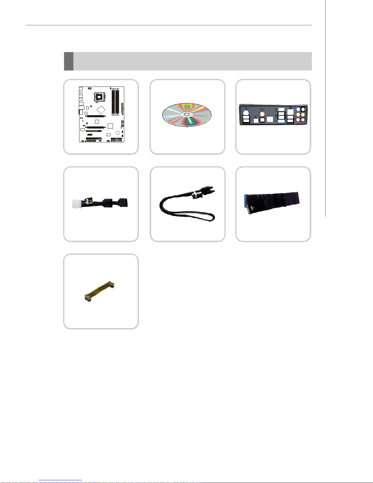
*The picturesareforreferenceonly.Yourpackingcontentsmayvarydependingon
the modelyou purchased.
PackingChecklist
Mainboard Driver/UtilityCD Back I/OShield
PowerCable SATACable StandardCablefor
IDEDevices
2-WaySLIbridgecable
PDFcreated withpdfFactoryProtrialversion www.pdffactory.com


2-1
HardwareSetup
HardwareSetup
Chapter2
Thischapterprovidesyou withtheinformation about
hardwaresetupprocedures.Whiledoingthe installation,
becarefulinholdingthecomponentsandfollowthe
installationprocedures.Forsomecomponents,ifyou
install inthewrong orientation,thecomponentswillnot
workproperly.
Useagroundedwrist strapbeforehandlingcomputer
components.Staticelectricitymaydamagethe
components.
PDFcreated withpdfFactoryProtrialversion www.pdffactory.com
750iMainboard
2-2
Quick ComponentsGuide
Memory,
p.2-7
JPWR1,
p.2-9
CPUFAN1,
p.2-16
CPU,
p.2-3
IDE1/2,
p.2-14
FDD1,
p.2-15
SATA1/2/3/4,
p.2-15
SYSFAN1,
p.2-16
J1394_1,
p.2-16
Slots,
p.2-28
JAUD1,
p.2-18
JCD1,
p.2-17
JFP1/2,
p.2-17
JUSB1,
p.2-19
JCOM1,
p.2-19
BackPanel,
p.2-11
JPWR2,
p.2-10
SYSFAN3,
p.2-16
JOC1,
p.2-20
SYSFAN2,
p.2-16
JSPDIF,
p.2-18
PDFcreated withpdfFactoryProtrialversion www.pdffactory.com
2-3
HardwareSetup
CPU(CentralProcessingUnit)
ThismainboardsupportsIntel processorsin theLGA775 package.Whenyouare
installingtheCPU, makesuretoinstallthecoolertoprevent overheating.Ifyou do not
havetheCPUcooler,consultyourdealerbeforeturning onthecomputer.
1.Overheatingwill seriouslydamagethe CPUand system.Alwaysmakesure
thecoolingfancanworkproperlytoprotecttheCPUfromoverheating.
Makesurethatyou applyaneven layerofthermalpaste(orthermaltape)
between theCPUand the heatsinktoenhanceheatdissipation.
2.Whilereplacing the CPU,always turnoff theATXpowersupplyorunplug
the powersupply spowercordfromthe grounded outlet firsttoensurethe
safetyofCPU.
3.Thismainboardisdesigned tosupportoverclocking.However,please
makesureyourcomponentsareable totoleratesuchabnormal setting,
whiledoing overclocking.Anyattempttooperatebeyondproductspecifi-
cationsisnotrecommended.Wedonotguarantee the damagesorrisks
caused byinadequateoperation orbeyondproductspecifications.
Important
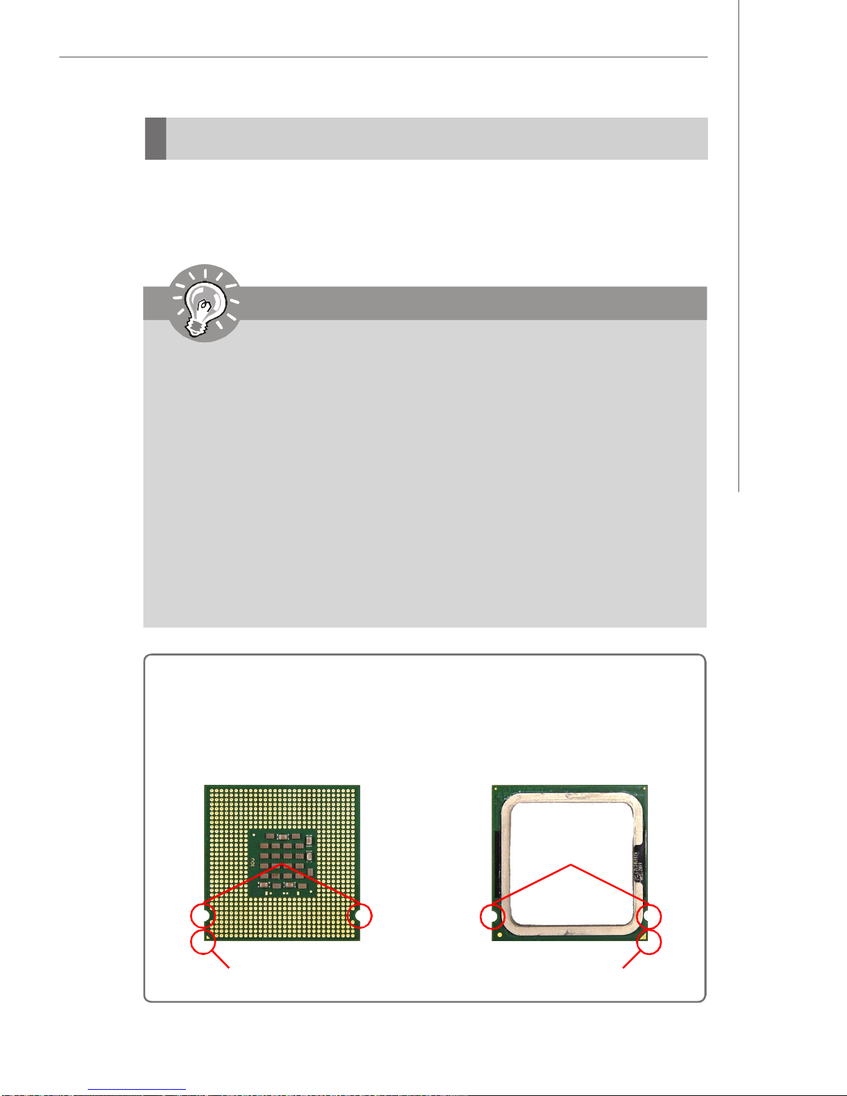
Introduction toLGA775 CPU
YellowtriangleisthePin1indicator
Alignment Key
The pin-pad sideofLGA775CPU.
YellowtriangleisthePin1indicator
Alignment Key
ThesurfaceofLGA775CPU.Re-
membertoapplysomethermalpaste
onitforbetterheat dispersion.
PDFcreated withpdfFactoryProtrialversion www.pdffactory.com
750iMainboard
2-4
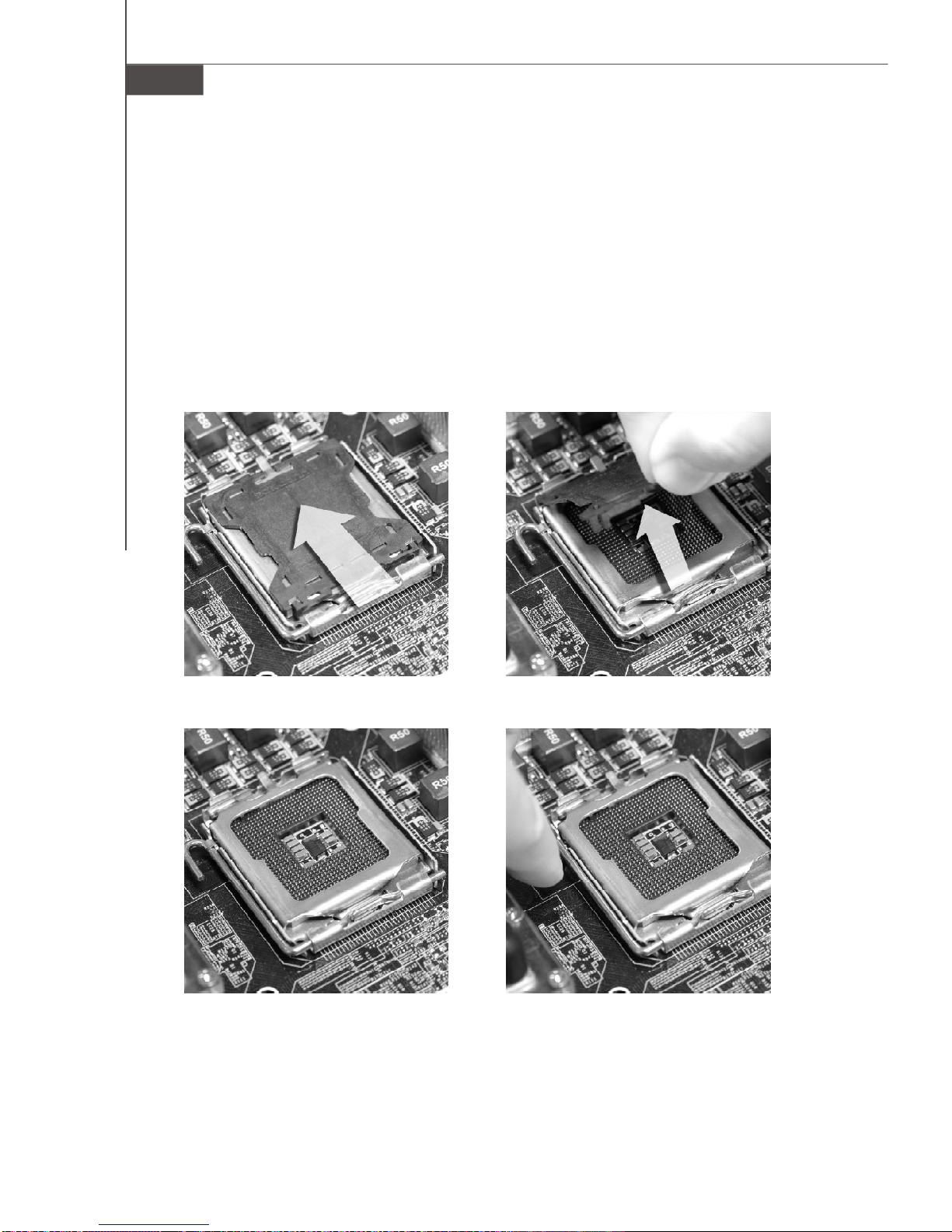
CPU&Cooler Installation
When you areinstallingtheCPU,makesuretheCPUhasacoolerattachedon thetop
toprevent overheating.Meanwhile, do notforget toapplysomethermalpasteonCPU
beforeinstallingtheheatsink/coolerfanforbetterheat dispersion.Followthesteps
belowtoinstalltheCPU&coolercorrectly. Wrong installation will causethedamage
ofyourCPU&mainboard.
2.Removethe capfromleverhinge
side(asthe arrowshows).
1.TheCPUsockethasaplasticcap
onittoprotectthe contactfrom
damage.Beforeyouinstall the
CPU,alwayscoverittoprotect
thesocketpin.
4.Opentheloadlever.3.Thepinsof socketreveal.
PDFcreated withpdfFactoryProtrialversion www.pdffactory.com

2-5
HardwareSetup
6.Afterconfirming theCPUdirec-
tion forcorrectmating,put down
the CPUinthesockethousing
frame.Besuretograsponthe
edgeof theCPUbase.Notethat
the alignmentkeysarematched.
5.Lifttheloadleverup andopen
theloadplate.
1.Confirmif yourCPUcoolerisfirmlyinstalledbeforeturningon yoursystem.
2.Donottouchthe CPUsocketpinstoavoiddamaging.
3.Theavailabilityofthe CPUland side coverdependson yourCPUpacking.
Important
Alignment Key
8.Coverthe loadplateontothe
package.
7.VisuallyinspectiftheCPUis
seatedwellintothe socket.If not,
takeout theCPUwithpureverti-
calmotionand reinstall.
PDFcreated withpdfFactoryProtrialversion www.pdffactory.com
750iMainboard
2-6
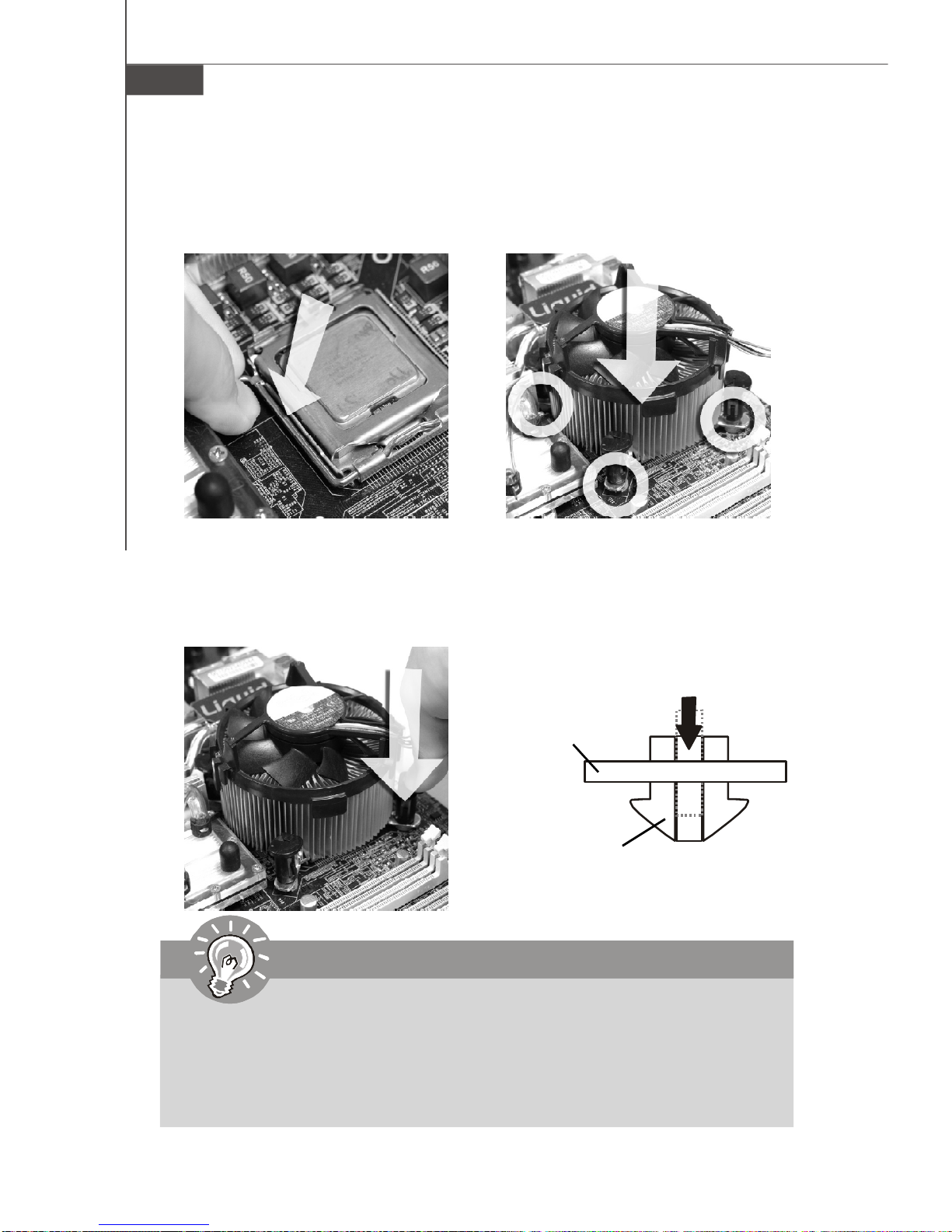
10.Align the holeson the mainboard
withtheheatsink.Pushdown
thecooleruntil itsfourclipsget
wedged intotheholesofthe
mainboard.
12.Turnoverthemainboardtocon-
firmthattheclip-endsarecor-
rectlyinserted.
9.Press downtheloadleverlightly
ontotheloadplate,and thense-
curethe leverwiththehookun-
derretentiontab.
1.WheneverCPUisnotinstalled,alwaysprotect yourCPUsocket pin withthe
plasticcap covered (showninFigure1)toavoiddamaging.
2.Mainboardphotosshowninthissection arefordemonstration of the CPU/
coolerinstallation only.Theappearanceofyourmainboardmayvaryde-
pending onthe modelyou purchase.
11.Press thefourhooksdownto
fastenthecooler.Then rotatethe
locking switch(refertothecor-
rect directionmarkedonit)tolock
thehooks.
LockingSwitch
Mainboard
Hook
Important
PDFcreated withpdfFactoryProtrialversion www.pdffactory.com

2-7
HardwareSetup
Memory
Dual-Channel modePopulation Rule
InDual-Channelmode,thememorymodulescantransmitand receivedatawithtwo
databuslinessimultaneously.EnablingDual-Channelmodecanenhancethesystem
performance.The following illustrationsexplain thepopulationrulesforDual-Channel
mode.
DIMM1
DIMM2
DIMM3
DIMM4
DIMM1
DIMM2
DIMM3
DIMM4
DIMM1
DIMM2
DIMM3
DIMM4
DIMM1
DIMM2
DIMM3
DIMM4
Empty
Installed
TheseDIMM slotsareusedforinstalling memorymodules.
Single-Channel:All DIMMsinGREEN.
Dual-Channel:ChannelAinGREEN; ChannelBinBlack.
DDR2
240-Pin/1.8V
64x2=128-Pin 56x2=112-Pin
PDFcreated withpdfFactoryProtrialversion www.pdffactory.com

750iMainboard
2-8
Installing Memory Modules
1.Thememorymodulehasonlyonenotchonthecenterand will onlyfitin theright
orientation.
2.Insertthememorymodule verticallyintotheDIMMslot.Thenpushitin until the
goldenfingeronthe memorymoduleisdeeplyinserted inthe DIMMslot.The plastic
clipateachsideoftheDIMM slot will automaticallyclosewhenthememorymodule
isproperlyseated.
3.Manuallycheckifthememorymodulehasbeenlockedin placebytheDIMM slot
clipsatthesides.
Important
Youcanbarelyseethegoldenfingerifthememorymodule isproperlyin-
serted inthe DIMM slot.
Volt Notch
Important
1. DDR2memorymodulesarenotinterchangeablewithDDRandtheDDR2
standardisnotbackwardscompatible. Youshould always install DDR2
memorymodulesinthe DDR2DIMM slots.
2.InDual-Channelmode,makesurethatyou install memorymodulesofthe
sametypeand densityindifferentchannelDIMM slots.
3.Toenablesuccessful systemboot-up,always insertthe memorymodules
intothe DIMM1first.
4.Duetothe chipsetresourcedeployment,thesystemdensitywillonlybe
detectedup to7+ GB(notfull 8GB)when eachDIMMisinstalled witha2
GBmemorymodule.
PDFcreated withpdfFactoryProtrialversion www.pdffactory.com
2-9
HardwareSetup
PowerSupply
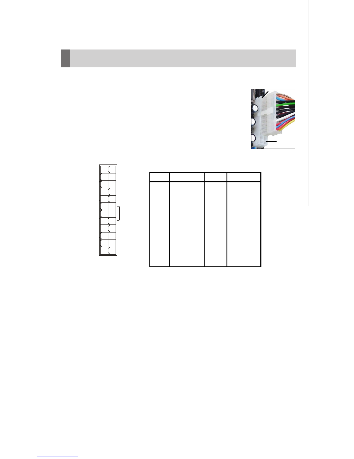
ATX24-Pin Power Connector:JPWR1
ThisconnectorallowsyoutoconnectanATX24-pinpowersupply.
ToconnecttheATX24-pin powersupply,makesuretheplugofthe
powersupplyisinsertedin theproperorientationand thepinsare
aligned.Then pushdownthe powersupplyfirmlyintotheconnector.
Youmayusethe20-pin ATXpowersupplyasyoulike.If you’dlike
tousethe20-pin ATXpowersupply,pleaseplug yourpowersup-
plyalong withpin 1&pin 13 (refertotheimage attherighthand). pin12
pin13
PinDefinition
PIN SIGNAL
13 +3.3V
14 -12V
15 GND
16 PS-ON#
17 GND
18 GND
19 GND
20 Res
21 +5V
22 +5V
23 +5V
24 GND
PIN SIGNAL
1 +3.3V
2 +3.3V
3 GND
4 +5V
5 GND
6 +5V
7 GND
8 PWROK
9 5VSB
10 +12V
11 +12V
12 +3.3V
JPWR1
12
1
24
13
PDFcreated withpdfFactoryProtrialversion www.pdffactory.com
750iMainboard
2-10
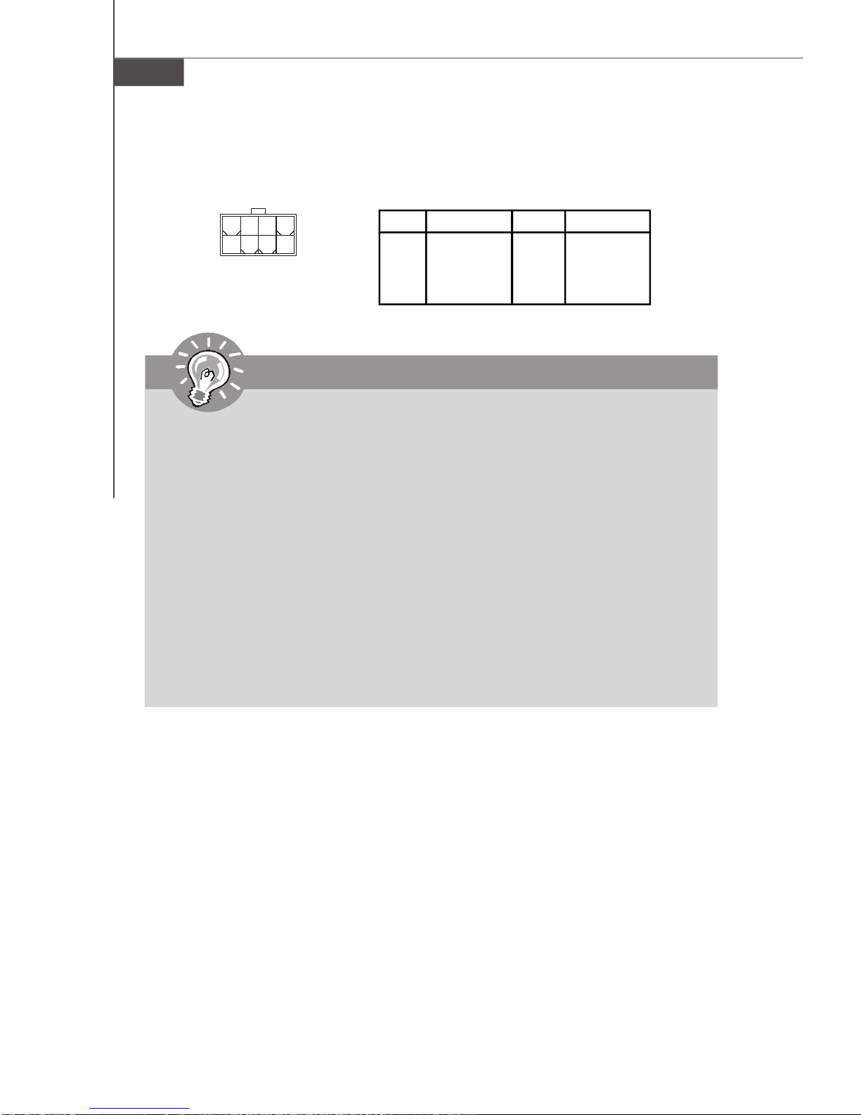
SSI8-Pin CPUPowerConnector:JPWR2
Thisconnectorprovides12Vpoweroutputtothe CPUs.
Important
1.Makesurethatallthe connectorsareconnectedtoproperATXpower
suppliestoensurestableoperationof themainboard.
2.Powersupplyof450watts(and above)ishighlyrecommended forsystem
stability.
3.nForcechipsetisverysensitivetoESD(ElectrostaticDischarge),there-
forethisissue mostlyhappenswhiletheusersintensivelyswap memory
modulesunderS5(power-off)states,and thepowercode isplugged while
installingmodules.Due toseveralpinsareverysensitivetoESD,sothis
kind ofmemory-replacementactionsmightcausesystemchipsetunable
toboot. Pleasefollowthe following solution toavoidthissituation:Unplug
the ACpowercableorunplug the powerconnectorsbeforethe1stinstal-
lation orduring systemupgrade procedure.
PinDefinition
PIN SIGNAL
5+12V
6+12V
7+12V
8+12V
PIN SIGNAL
1GND
2GND
3GND
4GND
JPWR2
5
1
8
4
PDFcreated withpdfFactoryProtrialversion www.pdffactory.com

2-11
HardwareSetup
BackPanel
Mouse/Keyboard
The standardPS/2 mouse/keyboardDINconnectorisforaPS/2 mouse/ keyboard.
USBPort
TheUSB (UniversalSerial Bus)port isforattachingUSB devicessuchaskeyboard,
mouse,orotherUSB-compatibledevices.
OpticalS/PDIF-Out
ThisSPDIF (Sony&PhilipsDigitalInterconnectFormat)connectorisprovidedfor
digitalaudiotransmissiontoexternalspeakersthrough anopticalfibercable.
CoaxialS/PDIF-Out
ThisSPDIF (Sony&PhilipsDigitalInterconnectFormat)connectorisprovidedfor
digital audiotransmissiontoexternalspeakersthrough acoaxialcable.
ClearCMOS
ThereisaCMOSRAMonboardthathasapowersupplyfromexternalbatteryto
keep thesystemconfigurationdata. Withthe CMOSRAM,thesystemcan automati-
callyboot OSeverytimeit isturnedon.If youwanttoclearthesystemconfiguration,
usethebuttontocleardata.Press thebuttontoclearthedata.
Mouse/
Keyboard
Clear
CMOS
IEEE1394
LAN
eSATAUSB USB
Line-In
Line-Out
Mic
RS-Out
CS-Out
SS-Out
Makesurethatyou poweroff the systembeforeclearing CMOSdata.
Important
Optical
S/PDIF-out
Coaxial
S/PDIF-out Debug
LED
PDFcreated withpdfFactoryProtrialversion www.pdffactory.com

750iMainboard
2-12
IEEE1394Port
The IEEE 1394portonthebackpanelprovidesconnectiontoIEEE 1394devices.
eSATAA
ThiseSATA(ExternalSerialATA) portisusedtoconnecttheexternalSATAdevice.
Youcanalsousethe optional externalSATAcabletoconnectSATAdeviceand
eSATAport.
LAN
The standardRJ-45LANjackisforconnectiontotheLocal Area Network(LAN). You
can connectanetworkcabletoit.
AudioPorts
Theseaudio connectorsareused foraudiodevices.Itiseasytodifferentiatebe-
tweenaudioeffectsaccordingtothecolorof audiojacks.
Line-In(Blue)- LineIn/Side-Surround Out in 7.1channelmode,isused
forexternalCD player,tapeplayerorotheraudiodevices.
Line-Out(Green)- LineOut, isaconnectorforspeakersorheadphones.
Mic(Pink)- Mic,isaconnectorformicrophones.
RS-Out(Black)- Rear-Surround Outin4/5.1/7.1channelmode.
CS-Out(Orange)- Center/ SubwooferOutin5.1/7.1channelmode.
SS-Out(Gray)- Side-Surround Out7.1channel mode.
LinkIndicatorActivityIndicator
Right
LED
Left
Color LEDState Condition
Yellow
Green
Orange
Off LANlinkisnotestablished.
On(steadystate) LANlinkisestablished.
On(brighter&pulsing) ThecomputeriscommunicatingwithanothercomputerontheLAN.
Off 10Mbit/ secdatarateis selected.
On 100Mbit/secdatarateisselected.
On 1000Mbit/secdatarateisselected.
PDFcreated withpdfFactoryProtrialversion www.pdffactory.com

2-13
HardwareSetup
Debug LED
Pleaserefertothe table belowtogetmoreinformationaboutthe DebugLEDmessage.
Post Status
FF Poweronand firstinitializeCPU.
D0,D4,D5 Initializememoryportdevice.
08 Initializekeyboard.
C0,C1,C2 EarlyCPUInitializeStart-DisableCache, Set up bootstrap
processorinformation.
C4, C6 InitializeHT(FSB).
2A,31 Initializeonboarddevices.LoadOptionROM(VGAand RAID
option ROM)formBIOStomemory.
37 Displaying sign-onmessage,CPUinformation,setupkey
messageand anyOEMspecificinformation.
38 InitializeUSB deviceand differentdevices.
3C Mid POST initializationof chipsetregisters. Detectdifferent
devices(parallelports,serialportsandcoprocessorinCPU…etc.)
75, 78 InitializeINT13 devicesandIPLdevices.(include SATA/PATA
HDD and CD ROM).
87 Entersetup screen.BIOSsetup if needed/requested.
A7 Displaythesystemconfigurationscreenifenabled.
A9 Waitforuserinputatconfigurationdisplayif needed.
B1 SavesystemcontextforACPI(Advanced Configuration andPower
Interface). PreparegivecontroltoOSloader(INT 19H).
00 PasscontroltoOSLoader(typicallyINT 19H).
AA EnterOS(VistaorWindowsXP).
PDFcreated withpdfFactoryProtrialversion www.pdffactory.com

750iMainboard
2-14
Connectors
IDEConnector:IDE1/2
ThisconnectorsupportsIDEharddiskdrives, opticaldiskdrivesandotherIDEdevices.
IDE1(PrimaryIDEConnector)
Thefirst harddriveshould alwaysbeconnectedtoIDE1. IDE1canconnect amaster
andaslavedrive.
IDE2(SecondaryIDEConnector)
IDE2canalsoconnectamasterand aslavedrive.
Important
If youinstalltwoIDEdevicesonthesamecable,you mustconfigurethe
drivesseparatelytomaster/slavemode bysettingjumpers.RefertoIDE
devicesdocumentationsuppliedbythevendorsforjumpersettinginstructions.
IDE2
IDE1
PDFcreated withpdfFactoryProtrialversion www.pdffactory.com
Other manuals for nForce 750i SLI
3
Table of contents
Other EVGA Motherboard manuals

EVGA
EVGA X58 SLI CLASSIFIED User manual

EVGA
EVGA Z97 User manual

EVGA
EVGA 112-CK-NF72-K1 User manual

EVGA
EVGA X79 Classified User manual

EVGA
EVGA X58 Classified3 User manual

EVGA
EVGA Z77 FTW User manual

EVGA
EVGA nForce 780i SLI FTW User manual

EVGA
EVGA Z68 FTW User manual

EVGA
EVGA EVGA X79 DARK System manual

EVGA
EVGA 133-P4-NF51-AX User manual

EVGA
EVGA Z77 Stinger User manual

EVGA
EVGA P55 FTW 200 User manual

EVGA
EVGA X299 Micro User manual

EVGA
EVGA 132-CK-NF79-A1 User manual

EVGA
EVGA P67 FTW User manual

EVGA
EVGA X79 SLI User manual

EVGA
EVGA Z97 User manual

EVGA
EVGA Classified SR-X User manual

EVGA
EVGA P67 SLI User manual

EVGA
EVGA Z170 STINGER User manual


