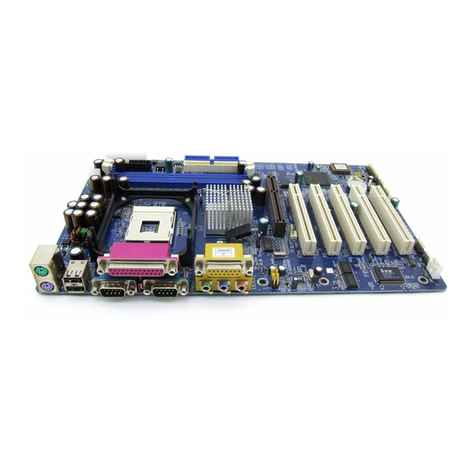
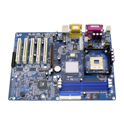
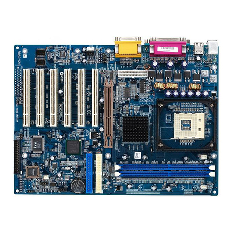
Shuttle AV42 User manual

AV42
Intel Pentium 4/Celeron
478-pin Processor
with 400/533 MHz FSB
Based DDR MAINBOARD
User's Manual

Shuttle®AV42
Intel Pentium 4/Celeron
478-pin Processor
with 400/533 MHz FSB
Based DDR Mainboard
Manual Version 1.0
Copyright
Copyright©2002 by Shuttle®Inc. All Rights Reserved.
This publication, including all photos, illustrations, and software, is protected under interna-
tional copyright laws, with all rights reserved. Reproducing any of the material contained
herein is prohibited without the consent of the publisher.
Disclaimer
This manual has repeatedly been rectified for less to criticize; however, it is inevitable to avoid
sliping up on something. Please inform us if there is anything that needs to be corrected or
improved. Information in this document is subject to change without notice. Shuttle®Inc.
makes no representations or warranties with respect to the contents hereof, and specifically
for any particular purpose. Shuttle®Inc. reserves the right to revise or change this publication
without obligation to notify any person of such revision or changes.
Trademarks
Shuttle is a registered trademark of Shuttle Inc.
VIA is a registered trademark of VIA Corporation.
Intel, Pentium, and Celeron are registered trademarks of Intel Corporation.
PS/2 is a registered trademark of IBM Corporation.
AWARD is a registered trademark of Award Software Inc.
Microsoft and Windows are registered trademarks of Microsoft Corporation.
General Notice: Other product names used in this manual are ascribed to their respective
owners and acknowledged.
M673

- 1 -
WHAT'S IN THE MANUAL ....................................................................... 5
Quick Reference .......................................................................................................... 5
About This Manual....................................................................................................... 5
1 INTRODUCTION.................................................................................... 6
1.1 TO DIFFERENT USERS....................................................................................... 6
FIRST-TIME DIY SYSTEM BUILDER................................................................... 6
EXPERIENCED DIY USER................................................................................... 6
SYSTEM INTEGRATOR ........................................................................................ 6
1.2 ITEM CHECKLIST: ................................................................................................ 7
2 FEATURES............................................................................................. 8
2.1 SPECIFICATIONS.................................................................................................. 8
3 HARDWARE INSTALLATION.............................................................. 11
3.1 STEP-BY-STEP INSTALLATION ...................................................................... 11
STEP 1 CPU Installation......................................................................................12
STEP 2 Set Jumpers ...........................................................................................14
STEP 3 Install DDR SDRAM System Memory..................................................14
STEP 4 Install Internal Peripherals in System Case .........................................15
STEP 5 Mount the Mainboard on the Computer Chassis................................16
STEP 6 Connect Front-Panel LEDs/Switch/USBs...........................................17
STEP 7 Connect IDE and Floppy Disk Drives ..................................................18
STEP 8 Connect Other Internal Peripherals ......................................................18
STEP 9 Connect the Power Supply ...................................................................19
STEP 10 Install Add-on Cards in Expansion Slots ...........................................19
STEP 11 Connect External Peripherals to Back-Panel....................................20
STEP 12 System Boot Up For the First-Time...................................................21
STEP 13 Install Drivers & Software Components.............................................22
3.2 JUMPER SETTINGS ...........................................................................................23
TABLE OF CONTENTS
- 2 -
JUMPERS & CONNECTORS GUIDE ...............................................................24
Jumpers
Clear CMOS Setting (JP1).................................................................................26
BIOS Written Protection (JP3) ............................................................................26
CPU FSB Setting (JP5).......................................................................................26
Back-Panel Connectors
PS/2 Mouse & Keyboard Connectors................................................................27
USB1/2 Port Connectors .....................................................................................27
COM1/2 Port Connectors ....................................................................................27
Parallel Port Connector........................................................................................27
Line-Out Port Connector ......................................................................................28
Line-In Port Connector .........................................................................................28
Mic-In Port Connector...........................................................................................28
MIDI/Game Port Connector..................................................................................28
Front-Panel Connectors
MSG LED Connector (Green/Power LED)........................................................29
HDDLED Connector(HDD LED).......................................................................29
ATX Power On/Off Switch Connector (PWR BTN)............................................30
Hardware Reset Connector (RST)......................................................................30
Extended USB Headers (USB2&3) ...................................................................31
Front-Panel Audio Header (AUDIO) ...................................................................31
Internal Peripheral Connectors
Enhanced IDE and Floppy Connectors ..............................................................32
Other Connectors
ATX Power Supply Connector (ATX1) ...............................................................33
Cooling Fan Connectors - CPUFAN1 & CASFAN1 .........................................34
Audio CD_IN Connectors (CD1/2) .....................................................................34

- 3 -
Single-ColorMSG LED(SJ1) .............................................................................35
IR Header (SIR).....................................................................................................35
3.3 SYSTEM MEMORY CONFIGURATION ............................................................36
INSTALL MEMORY ..............................................................................................36
UPGRADE MEMORY..........................................................................................36
4 SOFTWARE UTILITY.......................................................................... 37
4.1 Mainboard CD Overview ..................................................................................37
4.2 Install Mainboard AV42 Software ..................................................................37
4.2.A Install VIA Driver......................................................................................38
4.2.B Install Audio Device Driver...................................................................38
4.2.C Install USB 2.0 Driver ............................................................................ 39
4.3 View the User's Manual ...................................................................................39
5 BIOS SETUP ........................................................................................ 40
5.1 ENTER the BIOS..................................................................................................40
5.2 THE MAIN MENU .................................................................................................41
STANDARD CMOS FEATURES .......................................................................43
ADVANCED BIOS FEATURES..........................................................................45
ADVANCED CHIPSET FEATURES..................................................................48
INTEGRATED PERIPHERALS...........................................................................51
POWER MANAGEMENT SETUP .....................................................................54
PNP/PCI CONFIGURATIONS.............................................................................58
PC HEALTH STATUS ..........................................................................................60
FREQUENCY/VOLTAGE CONTROL ................................................................61
LOAD FAIL-SAFE DEFAULTS ...........................................................................62
LOAD OPTIMIZED DEFAULTS ..........................................................................62
SET SUPERVISOR/USER PASSWORD .........................................................62

- 4 -
SAVE & EXIT SETUP ..........................................................................................63
EXIT WITHOUT SAVING......................................................................................63

- 5 -
Quick Reference
Hardware Installation >> Step-by-Step .......................................................Page 11
Jumper Settings >> A Closer Look............................................................. Page 23
Software Utility >> How to Install................................................................ Page 37
BIOS Setup >> How to Configure............................................................... Page 40
About This Manual
For First-Time DIY System Builder ................................................................Page 6
For Experienced DIY User ...............................................................................Page 6
For System Integrator.......................................................................................Page 6
WHAT'S IN THE MANUAL

- 6 -
1.1 To Different Users
First-Time DIY System Builder
Welcome to the DIY world! Building your own computer system is not as diffi-
cult as you may think. To make your first computer DIY experience successful,
right from the start, we have designed the 3.1 Hardware Installationsection
in a step-by-step fashion for all the first-time DIY system builders. Prior to instal-
lation, we also suggest you to read the whole manual carefully to gain a com-
plete understanding of your new Shuttle AV42mainboard.
Experienced DIY User
Congratulate on your purchase of the Shuttle AV42mainboard. You will find
that installing your new Shuttle AV42 mainboard is just easy. Bundled with an
array of onboard functions, the highly-integrated AV42 mainboard provides
you with a total solution to build the most stable and reliable system. Refer to
sections 3.2 Jumper Settings andChapter 4 Drivers/Software Utilitiesto
find out how to get the best out of your new mainboard. Chapter 5 BIOS
Setup alsocontainsthe relevant information onhow to tune upyoursystem to
achieve higher performance.
System Integrator
You have wisely chosen this mainboard to construct your system. This
mainboard incorporates all the state-of-the-art technology of the P4X333
chipset from VIA. It integrates the most advanced functions you can find to
date in a compact ATX board.
1 INTRODUCTION

- 7 -
1.2 Item Checklist:
Check all items with your AV42 mainboard to make sure nothing is missing.
The complete package should include:
-One piece of the AV42 mainboard
-One piece of ATA133/100/66 Ribbon Cable
-One piece of Floppy Ribbon Cable
-One piece of twin-port USB Cable (optional)
-AV42 User's Manual
-One piece of Bundled CD-ROM with containing:
ØAV42 user's manual in PDF format
ØVIA driver
ØAudio device driver
ØUSB 2.0 driver
ØAward Flashing Utility
DIMM1
IT8705F
0239-FXS
MFL6W0
CPUFAN1
IDE1
1
AGP1
PCI1
CNR1
UM240445
0240
93718CF
CASFAN1
P4X333
0236CETAIWAN
2IA1019567
ROM2
A
TX
1
PANEL
1
SIR
1
AUDIO
USB2
1
BT1
R217 A
KA7500 B
SJ1
1
ID
E
2
1
1
DIMM2
DIMM3
JP3
1
J
P5
JP1
1
USB3
1
1
MKM
VT8235
0234CDTAIWAN
23A3031771
1
FDD1
PCI2
PCI3
PCI4
PCI5
1
27078S1234CRMC ALC101
1
CD2
CD1
UM740439
0238
950901BF

- 8 -
This mainboard is carefully designed for the demanding PC user who wants high perfor-
mance and maximum intelligent features in a compact package.
2.1 Specifications
-CPU Support
Intel Pentium 4/Celeron Processor with 400/533 MHz FSB.
-Chipset
Features VIA P4X333 N.B. and VIA VT8235 S.B..
-CPU FSB Configuration
AV42 provides jumper JP5 to configure front side bus at 400/533MHz.
-AC'97 Audio Codec
Compliant with AC'97 2.2 specifications.
Supports 18-bit ADC and DAC resolution and four analog line-level stereo
inputs.
-Versatile Memory Support
Three 184-pin DIMM slots to support up to 3GB of PC2100.
Compliant with DDR SDRAM module.
-Expansion Slots
Provide five 32-bit PCI slots, one AGP slot that supports up to 4X AGP de-
vice, and one CNR (Communications and Networking Riser) slot.
-6 USB 2.0 Interfaces Onboard
Ø2 x USB connectors on back-panel and two sets of dual USB port headers
on board.
-I/O Interface
Provides a variety of I/O interfaces:
Ø1 x Floppy interface for 3.5-inch FDD with 720KB, 1.44MB, or 2.88MB
format or for 5.25-inch FDD with 360K or 1.2MB format.
Ø2 x DB9 serial connectors 16C550 UART compatible.
Ø1 x Infrared communication port.
(Serial port COM2 can also be redirected to an external IrDA Adapter
for wireless connection.)
Ø1 x DB25 parallel connector that supports SPP, EPP, and ECP.
2 FEATURES

- 9 -
Ø1 x PS/2 Mouse connector.
Ø1 x PS/2 Keyboard connector.
Ø1 x Line-Out port.
Ø1 x Line-In port.
Ø1 x Mic-In port.
Ø1 x DB15 MIDI/Game port.
-PCI Bus Master IDE Controller Onboard
Two UltraDMA133/100/66 BusMaster Dual-ChannelIDEports providesup-
porttoamaximumoffourIDEdevices(oneMasterandoneSlaveperchannel).
The IDE Bus implements data transfer speeds of up to 133/100/66 MB/sec
and also supports Enhanced PIO Modes.
80-pin Cable Backward Compatible Legacy ATAPI Devices, ATAPI IDE CD-
ROM, CD-R, CD-RW, and LS-120 Supports.
-ATX Power Supply Connector
ATX power supply unit can connected to the onboard 20-pin Pentium 4
standard ATX power connector, supporting Suspend and Soft-On/Off by
dual-function power button.
-Advanced Configuration and Power Interface
Features four power-saving modes: S1 (Snoop), S3 (Suspend to RAM), S4
(Suspend to DISK), and S5 (Soft-Off). ACPI provides more efficient energy-
saving features controlled by your operating system that supports OS direct
Power Management (OSPM) functionality.
-System BIOS
Provides licensed Award BIOS V6.0 PG on 2Mb Flash core and supports
Green PC, Desktop Management Interface (DMI).
-ATX Form Factor
System board conforms to the ATX specification.
Board dimension: 305mm x 190mm.
-Advanced Features
ØLow EMI - Built in spread spectrum and automatic clock shut-off of
unused PCI/SDRAMS slots to reduce EMI.
ØDual Function Power Button - The system can be in one of two states,
one is Suspend mode and the other is Soft-Off mode. Pushing the power
button for less than 4 seconds places the system into Suspend mode.

- 10 -
When the power button is pressed for longer than 4 seconds, the system
enters Soft-Off mode.
ØCPU Clock Setting - This item allows users to adjust CPU Host Clock in
BIOS.
ØCPU Multiplier Setting - This item allows users to adjust CPU Multiplier
in BIOS.
-Intelligent Features
ØVoltage Monitoring - Monitors various voltages of key elements, such as
the CPU, and other critical system voltage levels to ensure stable current
passing through mainboard components.
ØFan Status Monitoring -To prevent CPU from overheating, the CPU fan
is monitored for RPM and failure. (CPU Cooling FAN with RPM sensor is
required.)
ØTemperature Monitoring - This item allows users to make sure whether
the CPU or system runs in a suitable temperature.

- 11 -
Before removing or installing any of these devices including CPU, DIMMs,
Add-On Cards, Cables, please make sure to unplug the onboard power
connector.
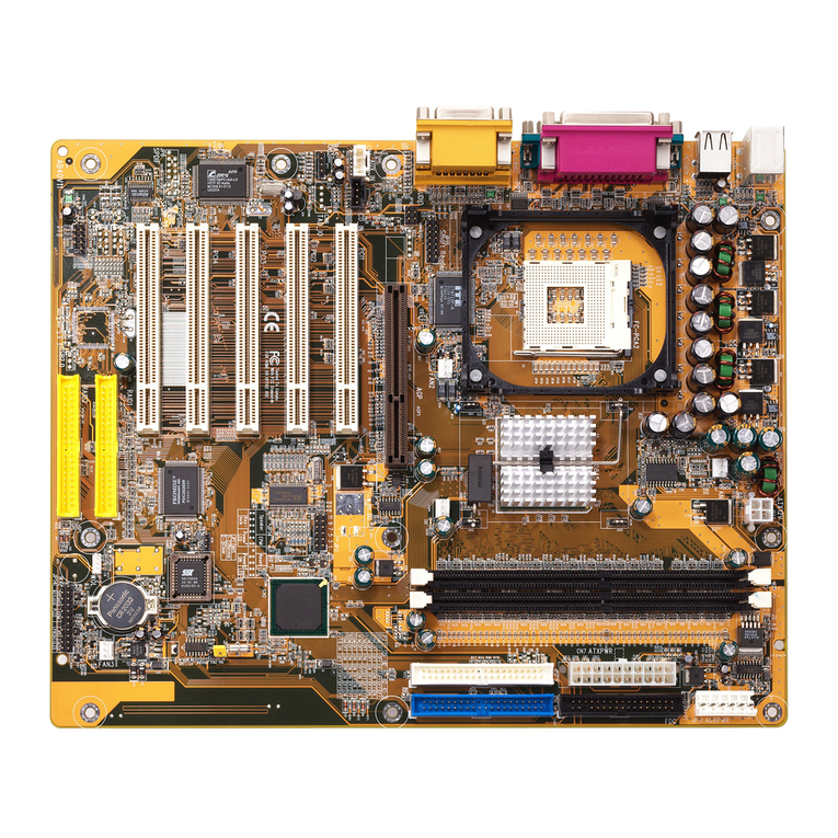
This section outlines how to install and configure your mainboard. Refer to the following
mainboard layout to help you to identify various jumpers, connectors, slots, and ports.
Then follow these steps designed to guide you through a quick and correct installation of
your system.
3.1 Step-by-Step Installation
3 HARDWARE INSTALLATION
Accessories Of the AV42 Mainboard
D
I
M
M
1
IT8705F
0239-FXS
MFL6W0
C
P
U
F
A
N
1
IDE1
1
AGP1
PCI1
CNR1
UM240445
0240
93718CF
CASFAN1
P4X333
0236CE TAIWAN
2IA1019567
ROM
2
A
T
X
1
PANEL
1
SIR
1
A
UD
IO
USB2
1
B
T
1
R
217A
KA7
500
B
SJ1
1
I
D
E
2
1
1
D
I
M
M
2
D
I
M
M
3
J
P
3
1
J
P
5
J
P1
1
USB3
1
1
MKM
VT8235
0234CD TAIWAN
23A3031771
1
FDD1
PCI2
PCI3
PCI4
PCI5
1
27078S1234C
RMC
ALC101
1
CD2
CD1
UM740439
0238
950901BF
Floppy Connector
Five PCI Slots
Audio CD_IN2 Connector
Audio CD_IN1 Connector
Two USB Ports
Parallel Port (LPT1)
Serial Ports (COM1&2)
Line-Out/Line-In/Mic-In &
Front-Panel Audio Header
PS/2 Keyboard & Mouse
Connectors
IR Header
Onboard Audio CODEC
MIDI/Game Ports
CASFAN1
One CNR Slot
Single-Color MSG LED
Front-Panel Connector
Extended USB Headers
(USB2&3)
Clear CMOS - JP1
BIOS Written
Protection - JP3
One AGP Slot
Two IDE Connectors
Three 184-Pin DIMM
Sockets
ATX Power Connector
CPUFAN1
Socket 478
CPU FSB - JP5

- 12 -
Step 1
CPU Installation:
This mainboard supports Intel Pentium 4/Celeron Socket 478 series CPU.
Please follow the steps as follows to finish CPU installation.
Note the CPU orientation when you plug it into CPU socket.
1. Pull up the CPU socket lever to 90-degree angle.
2. Locate Pin 1 in the socket and look for a black dot or cut edge on the CPU
upper interface. Match Pin 1 and cut edge, and insert the CPU into the
socket. CPU Pin 1 and cut edge
CPU socket lever up to
90-degree angle

- 13 -
3. Press down the CPU socket lever and finish CPU installation.
Note: The CPU might be damaged if you do not match the CPU
socket Pin 1 and cut edge well.
4. Intel Pentium 4/Celeron processor requires a set of heatsink and fan to cool
downthe processor.Youneed topurchase aheatsink andfanif theyare not
bundled with your CPU. Required is that install the set and plug its cable
in the CPU fan power connector. Note that there are kinds of CPU fan
connectors. Normally, if your mainboard supports a hardware monitoring
function,a 3-pinfan powerconnector canhave yoursystem detectthe CPU
fan's speed. A CPU fan with a 2-pin or 4-pin fan power connector does not
support the detection of the CPU fan's speed, and must directly be con-
nected to the system's power supply unit.

- 14 -
Step 2.
Set Jumpers
This mainboard is jumperless! The default jumper settings have been set for
the common usage standard of this mainboard. Therefore, you do not need
to reset the jumpers unless you require special adjustments as any of the
following cases:
Clear CMOS setting
BIOS written protection
CPU FSB setting
For first-time DIY system builders, we recommend that you not change the
default jumper settings if you are not totally familiar with the mainboard
configuration procedures. The factory-set default settings are tuned for opti-
mum system performance. For the advanced users who wish to customize
their system, section3.2 Jumper Settings will provide detailed information
on how to configure your AV42 mainboard manually.
Step 3
Install DDR SDRAM System Memory
To install memory, insert DDR SDRAM memory module(s) in DIMM slot(s).
Note that DDR SDRAM modules are directional and will not go in the DIMM
slots unless properly oriented. After the module is fully inserted into the
DIMM slot, lift the clips of both sides of the DIMM slot to lock the module in
place.
DDR SDRAM

- 15 -
Step 4
Install Internal Peripherals in System Case
Before you install and connect the mainboard into your system case, we
recommend that you first assemble all the internal peripheral devices into the
computer housing, including but not limited to the hard disk drive (IDE/
HDD), floppy disk drive (FDD), CD-ROM drive, and ATX power supply unit.
This will greatly facilitate in making the connections to the mainboard de-
scribed below.
To install IDE & FDD drives, follow this procedure:
1. Set the required jumpers on each device according to the instructions
provided by the manufacturer. (IDE devices, HDD, and CD-ROM have to
set jumpers to Master or Slave mode depending on whether you install
more than one device of each kind.)
2. Connect IDE cable and FDD cable on the back-panel of the internal
peripheral devices to the corresponding headers on board. Note that the
cable should be oriented with its colored stripe (usually red or magenta)
connected to pin#1 both on the mainboard IDE or FDD connector and on
the device as well.
3. Connect an available power cable from your system power supply unit to
the back-panel of each peripheral device. Note that the power cable is
directional and cannot fit in if not properly positioned.

- 16 -
Step 5
Mount the Mainboard on the Computer Chassis
1. You may find that there are a lot of different mounting hole positions
both on your computer chassis and on the mainboard. To choose
correct mounting holes, the key point is to keep the back-panel of the
mainboard in a close fit with your system case, as shown below.
2. After deciding on the proper mounting holes, position the studs between
the frame of the chassis and the mainboard. The studs are used to fix the
mainboard and to keep a certain distance between the system's chassis
and the mainboard, in order to avoid any electrical shorts between the
board and the metal frame of the chassis. (If your computer case is already
equipped with mounting studs, you will need to tighten screws to attach
the mainboard.)
Note: In most computer housings, you will be able to find 4 or more attach-
ment points to install mounting studs and then fix the mainboard. If
there are not enough matching holes, then make sure to install at
least 4 mounting studs to ensure proper attachment of the main-
board.

- 17 -
Step 6
Connect Front-Panel LEDs/Switch/USBs
You can find there are several different cables already existing in the system
case and originating from computer's front-panel devices (MSG LED, HDD
LED, PWR BTN, RST switch, or USB devices etc.). These cables serve to
connect the front-panel LEDs, switch, and USB connectors to mainboard's
front-panel connector groups (Panel and USB2&3), as shown below.
1. Green-LED and Power-LED (MSG LED)
2. HDD-LED (HDD LED)
3. ATX Soft Power On/Off (PWR BTN)
4. Hardware Reset Switch Button (RST)
5. Extended USB Headers (USB 2&3)
USB 2&3
1
PANEL
PWR BTN
MSG LED
-
+
1
HDD LED
RST
VREG_FP_USBPWR0
USB_FP_P0+
GND
KEY
USB_FP_P0-
5
1
USB 2&3
VREG_FP_USBPWR0
USB_FP_P1+
GND
USB_FP_P1-
USB_FP_OC0
HDDLED
3
1
1
24
MSG LED
PWRBTN
+
_
RST

- 18 -
Step 7
Connect IDE and Floppy Disk Drives
1. IDE cable connectors
2. Floppy cable connector
Step 8
Connect Other Internal Peripherals
1. Audio CD_IN1/2 connectors
IDE1
IDE2
1 1
1
FDD1
C
D
2
C
D
1
1
AUDIO
2. Front-panel audio header
Table of contents
Other Shuttle Motherboard manuals

Shuttle
Shuttle Spacewalker AB30 User manual

Shuttle
Shuttle FT20 User manual

Shuttle
Shuttle Spacewalker AK31 User manual

Shuttle
Shuttle FS51 User manual

Shuttle
Shuttle FV24 User manual

Shuttle
Shuttle AN51R User manual

Shuttle
Shuttle FN45 User manual

Shuttle
Shuttle ME21 User manual

Shuttle
Shuttle HOT-681 User manual

Shuttle
Shuttle AK35GT User manual

Shuttle
Shuttle MB47N User manual

Shuttle
Shuttle HOT-595 User manual

Shuttle
Shuttle AB60/R User manual

Shuttle
Shuttle SH610R4 Series User manual

Shuttle
Shuttle MV21 User manual

Shuttle
Shuttle FN95 User manual

Shuttle
Shuttle ME62 User manual

Shuttle
Shuttle MV43P User manual

Shuttle
Shuttle av61 User manual

Shuttle
Shuttle FN85 User manual