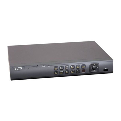
Risco VUpoint RVNVR04002FB User manual

VUpoint
Network Video Recorder
Models: RVNVR04002FB/ RVNVR04002QB/ RVNVR08002QB/ RVNVR16002FB/ RVNVR324K1FB
EN
Installation Guide
FR
IT
ES

Language
Page
3
23
43
63
EN
FR
IT
ES

VUpoint
Network Video Recorder
Models: RVNVR04002FB/ RVNVR04002QB/ RVNVR08002QB/ RVNVR16002FB/ RVNVR324K1FB
EN
Installation Guide

4
Safety Precautions
These instructions are intended to ensure that the user can use the product correctly to
avoid danger or property loss.
WARNINGS:
Installation or usage of this product that is not in accordance with the intended
use as defined by the supplier and as described in the instructional materials
can result in damage, injury, or death.
Make sure this product is not accessible by children and those for whom
operation of the system is not intended.
All installation and operation should conform to your local electrical safety
codes. The power shall conform to the requirement in the SELV (Safety Extra
Low Voltage) and the Limited power source is rated 12V DC in the IEC62368-1.
If the device is permanently connected to an electrical power supply, then the
connection should include an easily-accessible disconnection device, such as a
circuit breaker. Do not connect the two power supplying sources to the device
at the same time; it may result in device damage!
Do not ever attempt to repair your device by yourself, as doing so could result
in damage, injury or death –always contact your installer / supplier agent for
service.
CAUTIONS:
Make sure the power supply voltage is correct before using the NVR.
Do not drop the NVR or subject it to physical shock.
To avoid heat accumulation, good ventilation is required for a proper operating
environment.
Keep the NVR away from water and any liquid.
While shipping, the NVR should be packed in its original packing.
NOTE: We assume no liability or responsibility for all the fires or electrical shock
caused by improper handling or installation. We are not liable for any problems caused
by unauthorized modification or attempted repair.

5
Introduction
Thank you for purchasing the RVNVR04002FB/ RVNVR04002QB/
RVNVR08002QB/ RVNVR16002FB/ RVNVR324K1FB Network Video Recorder.
This Quick Start Guide will help you become familiar with your NVR in a very
short time.
Components and Accessories
NVR:
Installation Guide

6
4/16 Channel NVR Rear Panel Components
Figure 1 RVNVR04002FB/RVNVR16002FB NVR Components
NOTE: For Australia/USA, the approved AC/DC adapter shall be used
according to the country’s regulations.
4 Channel PoE NVR Rear Panel Components
Figure 2 RVNVR04002QB Components
NOTE: For Australia/USA, it is required to replace the AC power cable
according to the country’s regulations.
8 Channel PoE NVR Rear Panel Components
Figure 3 RVNVR08002QB NVR Components
NOTE: For Australia/USA, the approved AC/DC adapter shall be used
according to the country’s regulations.
Power Input Port
PoE Ports to
Connect to
Network Camera
Ethernet Port
VGA Port
HDMI Port
USB Port

7
Channel NVR Rear Panel Components
Figure 4 RVNVR324K1FB NVR Components
NOTE: For Australia/USA, it is required to replace the AC power cable
according to the country’s regulations.
Power Switch
AUDIO OUT,
RCA Connector
Alarm In/Out
Power Input
Network Port
VGA Port
AUDIO IN,
RCA Connector
HDMI Port
USB Port
Ground

8
HDD Installation
DANGER
Shut down the device and then unplug the power cable before you open the
case to replace the HDD!
All figures listed below are for reference only!
For first time installation, please check if the HDD was previously installed.
Please use HDD of 7200rpm or higher.
4/16 Channel
Loosen the screws on
the bottom of the chassis.
Align the HDD with
the four holes in the
bottom.
Turn the device
upside down and then
secure the screws
(supplied) firmly.
Connect the Data
cable and power cable to
the HDD and the
mainboard respectively.
Put back the cover
and then attach the
screws to the rear panel.
The installation is
complete.

9
32 Channel
Loosen the screws on
the rear panel and side
panel.
Align the HDD with
the four holes in the
bottom.
Turn the device
upside down and then
secure the screws
(supplied) firmly.
Connect the Data
cable and power cable to
the HDD and the
mainboard respectively.
Put back the cover
and then attach the
screws to the rear panel
and side panel. The
installation is complete.

10
NVRs and the RISCO Cloud Installer Application
The RISCO Cloud Installer Application provides an interface to your NVR. This
enables you to add an NVR or edit an existing one.
IMPORTANT –An NVR must first be physically installed before adding the
NVR to the system.
Adding an NVR
To add an NVR:
1. Log into the RISCO Cloud Installer Web Interface (for instructions, refer to
the RISCO Cloud Quick Installer Guide).
Figure 5 Sites List Page
2. From the Sites List page, select the Site you wish to add an NVR.
3. From the page that opens, click the IP CAMERAS Sub Tab and then the
NVR Side Tab.
Figure 6 NVR Page

11
4. Click the Add New NVR button; the Add New NVR side panel opens.
Figure 7 Add NVR Side Panel
5. Enter a name for the NVR.
6. Enter the MAC address of the NVR.
7. Click the Add button; the NVR will be added to the network.
Figure 8 NVR Added

12
All the cameras that are connected to the NVR’s LAN will be automatically
detected and displayed on the side panel.
8. Select the boxes of the IP Cameras to be added to the NVR.
NOTE: Only the IP Cameras in the list that are enabled can be added. In rare cases,
when IP Cameras are on the same LAN and are connected to another site, they will
be displayed but not enabled.
Figure 9 Select Camera for NVR
9. Click Next. A Wizard will guide you through the settings of each of the
selected cameras. You can quit the Wizard at any stage.
The Wizard screens contain mostly read-only information. For each camera
you should select only the required recording mode.

13
Figure 10 Add Camera
10. Recording Mode: If “Motion Detected” is selected, the NVR will record only
if motion is detected by the camera. If continuous is selected, the camera
will record continuously.
11. Click Save & Continue. Repeat the procedure for the other cameras until all
cameras you have selected for the NVR are setup. The following screen
provides a summary of the cameras that have been connected successfully
or that failed to be connected to the NVR.
12. For Wi-Fi Cameras, the following screen opens.
Figure 11 Connecting to Wi-Fi

14
13. Select the required network and then enter the password.
Figure 12 Selecting Wi-Fi network
14. Click Connect; the connect to Wi-Fi screen opens.
Figure 13 Connecting to Wi-Fi
15. Press OK.

15
Figure 14 Summary of Cameras Added to NVR
16. The defined NVR is displayed in the NVR page and is now added to the
site.
Figure 15 NVR Page

16
Editing an NVR
You can edit a selected NVR and add or remove cameras from the NVR.
To edit an NVR:
1. From the NVR page, click the NVR Name; the Edit NVR screen opens.
Figure 16 Edit NVR Screen
Field
Description
Name
Change the name of the NVR, if required
Firmware
Click Check to confirm if a new firmware version is available.
Local Access
Click Set and then select UI/CGI to enable access to the NVR’s web
interface for a time period of 60 minutes.
NOTE: You can delete the NVR from the site by clicking Delete NVR from the
bottom right of the screen.
RVNVR080020

17
Figure 17 Edit NVR Settings
2. Click Save to save the current settings or click Edit Cameras to edit Site
cameras; the Cameras list that appears provides information on the cameras
that are connected to the NVR and the cameras that are on the NVR
network but were not added to the NVR.
RVNVR080020

18
Figure 18 Edit NVR Cameras
3. If you wish to add a camera to the NVR, select the checkbox of the camera
that you wish to add and click Add Cameras. The Add Camera side panel
opens.
Cameras that
are already
connected to
the NVR
}
Cameras that
can be added
}

19
Figure 19 Add Camera
4. From the screen that opens, select the Camera Type and the Recording
Mode. If “Motion Detected” is selected, the NVR will record only if motion
is detected by the camera. If continuous is selected, the camera will record
continuously.
5. After making your selection, click Save & Continue.

20
The following screen provides a summary of the cameras that have been
newly added to the NVR.
Figure 20 Cameras Added to NVR
6. Click OK.
1 camera added to the NVR
This manual suits for next models
4
Table of contents
Languages:
Other Risco Network Hardware manuals
Popular Network Hardware manuals by other brands
Idis
Idis DR-8364D installation manual
Nortel
Nortel BayStack 100-S release note
NetComm
NetComm Freshtel NB9W Firmware update instructions
Multilink
Multilink Power Stone Instruction and programming manual
Idis
Idis DirectIP DR-1304P installation manual
Digital Watchdog
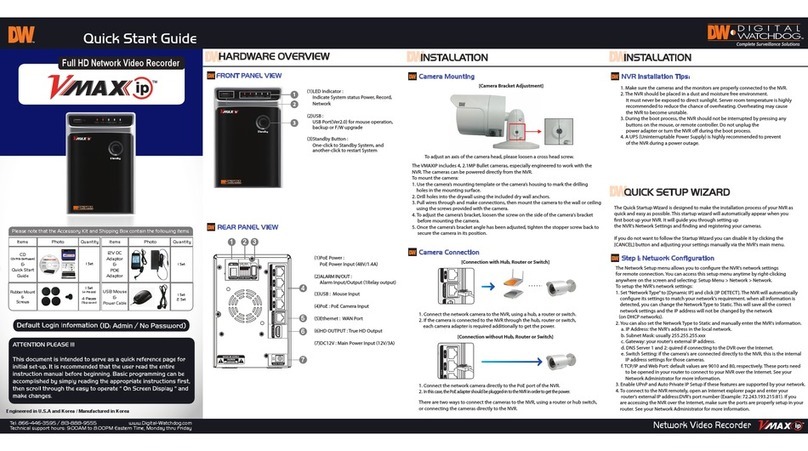
Digital Watchdog VMAX IP quick start guide


