8 - CP1/2/4
CPU Board - Installation and configuration
GENERAL INFORMATION
Control unit for one or more bollards in the Vigilant and Force series, available in
several versions:
CP1 unit for 1 Vigilant 500/I bollard (Fig.1)
CP2 unit for 2 Vigilant 500/I bollards (Fig.2)
CP4 unit for 4 Vigilant 500/I bollards (Fig.3)
CP1S unit for 1 Vigilant 800/I or Force 525/I-Force 825/I bollard (Fig.1)
CP2S unit for 2 Vigilant 800/I or Force 525/I-Force 825/I bollards (Fig.2)
CP4S unit for 4 Vigilant 800/I or Force 525/I bollards (Fig.3)
All the units above can also be provided with a pre-cabled emergency battery unit
(UPS) CP1K-CP2K-CP4K and CP1SK-CP2SK-CP4SK.
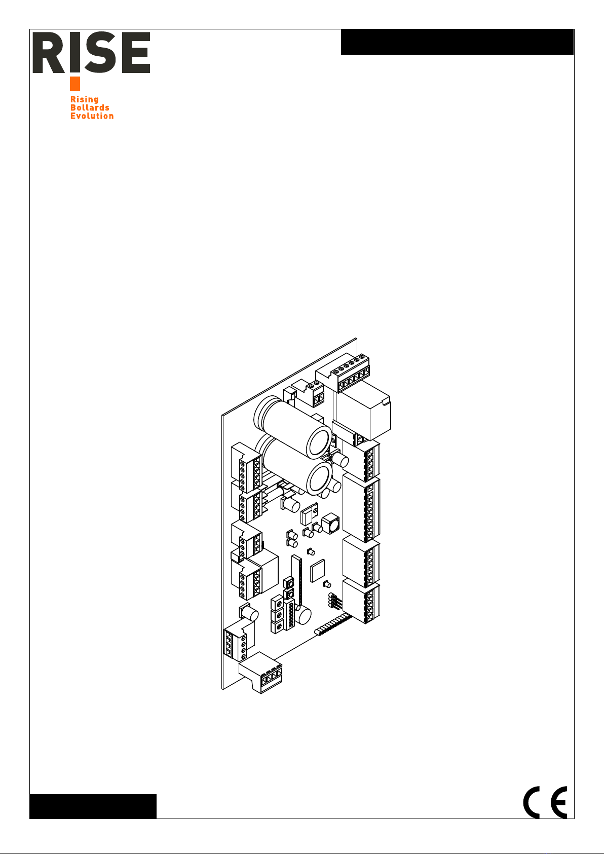
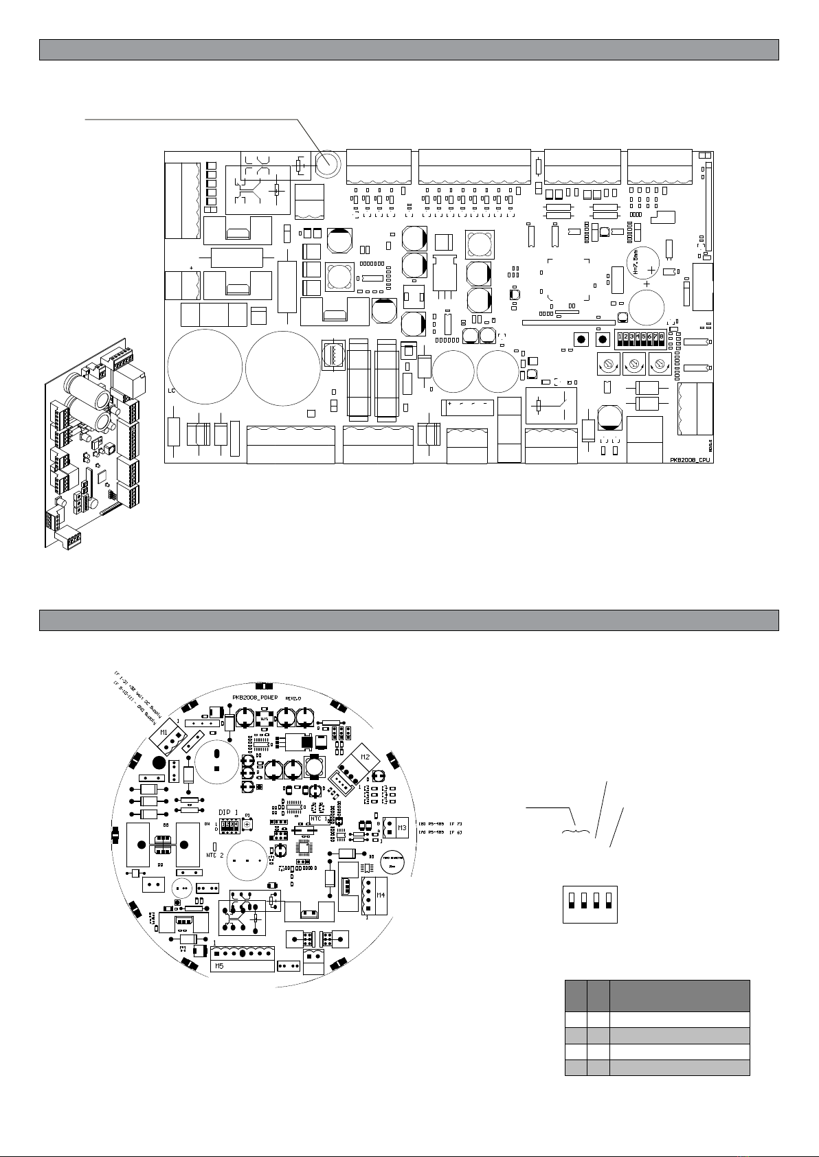
All the units have CPU control logics (Fig.4).
All the Force and Vigilant bollards have a POWER control board situated under the cover
of the cylinder (Fig. 5).
Connect the control unit and bollard using the cable with IP68 quick connector, which
comes in various lengths according to the distance between the unit and the bol-
lard.
ELECTRICAL CONNECTIONS
Refer to the wiring diagram for the number of bollards to be connected to the unit:
Fig.6 Connection of CP1/CP1S/CP1K/CP1SK to 1 bollard.
Fig.7 Connection of CP2/CP2S/CP2K/CP2SK to 2 bollards.
Fig.8 Connection of CP4/CP4S/CP4K/CP4SK to 4 bollards.
If using more than 1 bollard, EACH BOLLARD MUST BE ASSIGNED A DIFFERENT
ADDRESS ON THE POWER BOARD using the DIP1 switch shown in Fig. 5.
When connecting a single bollard, the wires should be attached directly to the extractable
connectors on the CPU board (as shown in the diagrams).
In the case of units CP2 and CP4, the CPU board is connected to a terminal block in line
that replicates the numbers of the connectors on the CPU board.
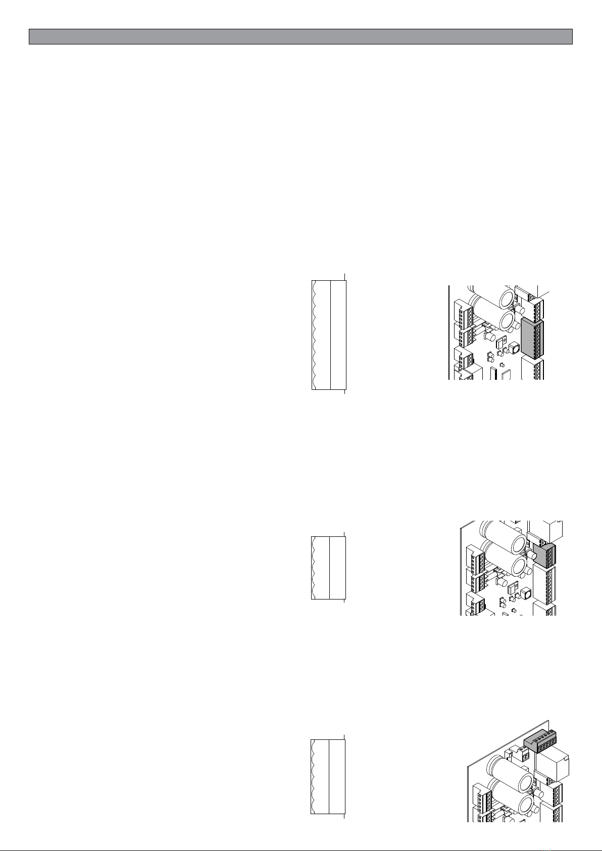
A note on 250V power supply: the unit supplied is usually for a mains voltage of 230V. If
the mains voltage is more than 230V (240/250V), simply remove the wire (marked 230V)
between the transformer and the output of the fuse holder (L), and in its place connect the
wire marked 250V, as shown in Figures 1/2/3.
The CPU control board is the same for all versions of the unit. The functions of the various
inputs/outputs and operating logics are described further on.
In the interest of simplicity, please refer to the illustrations of the CP1 board. The connec-
tions and functions are, in any case, the same for the CP2 and CP4 units.
IMPORTANT: The units for 2 and 4 bollards have an ABC terminal block for controlling
use of the bollard even when the board is broken or there is no power supply. Refer to the
section on the “ABC Terminal Block”.
At the end of this manual are various wiring diagrams for all the units. These illustrate the
connections between the CPU and the power supply, the transformer, the electric brake
batteries and an optional relay (KA1) for automatic lowering in the event of a power cut*.
Instructions are also given on how to connect the M10 terminal block to the control relay
of the green/red light.
The bollard is normally held in place by an electric brake. In the absence of power supply
on CP1/2/4 board, the batteries feed the electric brake allowing the descent of the bollard.
This function is performed automatically when the relay KA1 is installed.
Advice for installation
a) The electrical installation and the operating logic must conform with the regula-
tions in force.
b) It is advisable to keep the power cable (motor, power supply) separate from the
control cables (buttons, photocells, radio); to avoid interference it is preferable to
provide and use two separate sheaths (see EN 60204-1 15.1.3).
c) Check all the connections made again before powering up.
d) Check that the Dip Switch settings are as desired.
e) The N.C. inputs that are not used must remain free.
ATTENTION!
The faston and/or M5 connector is disconnected from the batteries upon delivery
of the unit.
Reconnect to the batteries only after connecting the power.
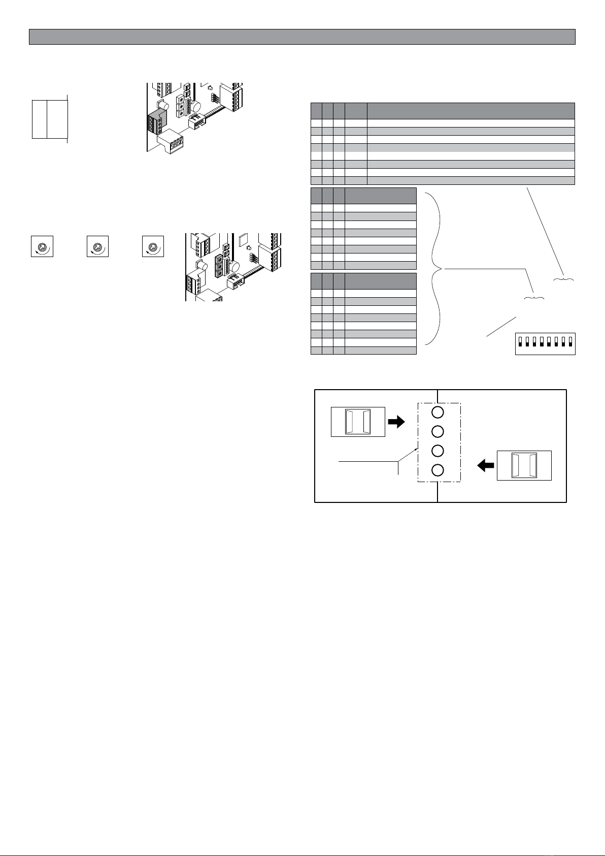
FUNCTION OF THE CPU INPUTS/OUTPUTS
Inputs/Outputs function
There are terminal boards for connection:
Terminal board M9 - pin 9.1-9.9
8 digital control inputs of which:
4 inputs to control the rising/descent of the bollards in “STEP by STEP” mode (when
the key is pressed, if the bollard is down it is lifted and vice-versa)
2 inputs for general control:
Input 9.6: “ALL DOWN” all the bollards connected to the control unit go down IR-
RESPECTIVE OF THEIR POSITION
Input 9.7: “ALL UP” all the bollards connected to the control unit rise IRRESPECTIVE
OF THEIR POSITION. It is recommended to have these controls always available to
synchronise the bollards or to make an emergency descent.
Input 9.8: "PROTECTION INVERSION”. Input with N.O. contact for photocell or ex-
ternal control device. During ascent maneuver, the intervention of this input causes the
immediate reversal of the maneuver. To be used as additional protection to other protec-
tions (loops and / or photocells).
All the inputs are of the “clean contact” (N.O.) type so they may be controlled by all
the control modules in clean contact with output relays such as radio control receiv-
ers, transponder receivers, numerical keypad receivers, normal up/down buttons
and any module with a clean contact relay at output: it is sufcient to connect the
common wire of the terminal board M9 pin 9.1 - Com in to the desired control.
Terminal board M13 - pin 13.1-13.5
Input terminal block N.C. contacts for Protection devices (loops or Photocell).
Always use the contact M13.1/M13.2 for general controls. In the case of step by step
functions
on conguring the "SP1", up to 4 independent safety devices for each bollard can be
used.
ALWAYS FOLLOW the conguration order related to the bollard:
LOOP INPUT 1> BOLLARD 1
LOOP INPUT 2> BOLLARD 2
LOOP INPUT 3> BOLLARD 3
LOOP INPUT 4> BOLLARD 4
General controls: LOOP INPUT 1> BOLLARD 1+2+3+4
Terminal board M6 - pin 6.1-6.6
Emergency terminal board: for making the bollards go down in the event of a power
cut and/or faulty boards there is a RED button on the board for making an emergency
descent (electronic faults); in this case the software is bypassed and the bollards are
positioned at ground level by holding the button down for the necessary time; on the
electromechanical box that houses the control unit there may be further terminals
for releasing and lifting the bollards, for removing the cover and changing the power
boards, the motor, etc. … in the case where these are faulty and no electronic com-
mand or software is working - (at least the motor brake must be working, the wiring
must not be interrupted and the batteries must be charged).
M9
9.1
9.2
9.3
9.4
9.5
9.6
9.7
9.8
9.9
- COM IN Control
UP DOWN 1
UP DOWN 2
UP DOWN 3
UP DOWN 4
ALL DOWN
ALL UP
INVERSION PROTECT
RESERVED 2
RESERVED
PROTECTION AGAINST INVERSION
ALL UP
ALL DOWN
STEP/STEP BOLLARD 4
STEP/STEP BOLLARD 3
STEP/STEP BOLLARD 2
STEP/STEP BOLLARD 1
M9 CONTROL COMMON
M13
- COM IN Induction Loop
IN Induction Loop 1
RESERVED
RESERVED
RESERVED
13.1
13.2
13.3
13.4
13.5 LOOP INPUT 4
LOOP INPUT 3
LOOP INPUT 2
LOOP 1 INPUT / MASTER
COMMON LOOP
M6
6.1
6.2
6.3
6.4
6.5
6.6
[F 3] + MOTORS EMERGENCY 24VDC
[F 5] + BRAKE 1 EMERGENCY 24VDC
[F 5] + BRAKE 2 EMERGENCY 24VDC
[F 5] + BRAKE 3 EMERGENCY 24VDC
[F 5] + BRAKE 4 EMERGENCY 24VDC
[F 4] + EMERGENCY CONTROLS 24VDC
+ 24Vdc EMERGENCY control (wire 4)
+ 24Vdc Brake 4 in EMERGENCY
+ 24Vdc Brake 3 in EMERGENCY
+ 24Vdc Brake 2 in EMERGENCY
+ 24Vdc Brake 1 in EMERGENCY (wire 5)
+ 24Vdc Motor in EMERGENCY (wire 3)