RITE-HITE FLASHFOLD 1390 User manual

This Manual Covers Serial No. 42994 and Units Shipped to Date, Refer to 1390B for Units Prior to 3-13-2008.
PRINTED IN U.S.A. Publication No. 1390E
FLASHFOLDTM
Bottom-Up Curtain

TABLE OF CONTENTS
INSTALLATION INSTRUCTIONS . . . . . . . . . . . . . . . . . . . . .3
FRAME INSTALLATION . . . . . . . . . . . . . . . . . . . . . . . . . . . .5
LIMIT SWITCH ADJUSTMENTS . . . . . . . . . . . . . . . . . . . . . .9
TROUBLESHOOTING / MAINTENANCE . . . . . . . . . . . . . .10
ELECTRICAL DRAWINGS . . . . . . . . . . . . . . . . . . . . . . . . .12
SERVICE PARTS/LIST . . . . . . . . . . . . . . . . . . . . . . . . . . . .15
ARCHITECTURAL DRAWING . . . . . . . . . . . . . . . . . . . . . . .19
WARRANTY . . . . . . . . . . . . . . . . . . . . . . . . . . . . . . . . . . . . . . .last page
NOTICE TO END USER
Our mission is to “Improve Industrial Safety, Security and
Productivity Worldwide Through Quality and Innovation.”
Thank you for purchasing the FLASHFOLD™ barrier unit by
RITE-HITE®MACHINE GUARDING. The FLASHFOLD is
intended to provide isolation to employees from flying debris
and flash protection in welding areas or machine guarding
areas. This curtain is intended to open from the bottom and
close or separate going up to provide safety and access to work
areas.
The FLASHFOLD, which is supplied with a motor assembly,
frame, curtain and offers an optional interlock switch, curtain
guides and a control box. The information contained in this
manual will allow you to operate and maintain the door in a
manner which will insure maximum life and trouble free operation.
When ordering parts through Aftermarket or Warranty
department, always include your model serial or SO# to be sure
that you receive the correct parts. The SO# and serial # for your
product is located on a label on the side of the control box. The
actual parts used on your door may be different than shown in
this manual due to special engineering or product improvement.
Your local representative provides a Planned Maintenance
Program (P.M.P.) which can be fitted to your specific operation.
Call your local representative or RITE-HITE MACHINE
GUARDING at 1-563-587-4401 or toll free at 1-800-553-5560. If
any procedures for the installation, operation or maintenance of
the FLASHFOLD system have been left out of this manual or
are not complete, contact Technical Support at 1-563-589-2722.
FEATURES
- Automatic, ergonomically correct, allows hands free operation.
- Heavy-Duty, U.V. protected curtain fabric protects operator
from intense light and flying debris.
- Smooth, fast opening operation.
TOOLS AND MATERIAL REQUIRED
7/16” & 9/16” [11 & 14] Open End Wrench or Ratchet Wrench
7/16” & 9/16” [11 & 14] Socket Set
Allen Wrench Set
13mm Socket
Phillips Screwdriver
Straight Screwdriver (small 1/8” [3] blade)
Hammer Drill (Optional)
Extension Cord (Optional)
3/8” or 1/2” [10 or 13] Masonry Bits (Optional)
Drill (3/8” or 1/2”) [10 or 13] w/Phillips Bit
5/16” [8] Hex Driver Bit For Drill
Tape Measure 25’ [7620] Minimum
Wire Strippers and Side Cutters
Retaining Ring Pliers
Carpenters Level
Water Level
Multi-Meter
Step Ladder
Hardware for mounting, shimming and anchoring to the floor are
not provided.
LOCKOUT/TAGOUT PROCEDURES
The Occupational Safety and Health Administration requires
that, in addition to posting safety warnings and barricading the
work area, the power supply has been locked in the OFF posi-
tion or disconnected. It is mandatory that an approved lockout
device is utilized. An example of a lockout device is illustrated.
The proper lockout procedure requires that the person responsi-
ble for the repairs is the only person who has the ability to
remove the lockout device.
In addition to the lockout device, it is also a requirement to tag
the power control in a manner that will clearly note that repairs
are under way and state who is responsible for the lockout con-
dition. Tagout devices have to
be constructed and printed so
that exposure to weather condi-
tions or wet and damp locations
will not cause the tag to deterio-
rate or become unreadable.
Rite-Hite does not recommend
any particular lockout device,
but recommends the utilization
of an OSHA approved device
(refer to OSHA regulation
1910.147). Rite-Hite
Corporation also recommends
the review and implementation
of an entire safety program for
the Control of Hazardous
Energy (Lockout/Tagout). These
regulations are available
through OSHA publication
3120.
2PUB. NO. 1390E APRIL 2014
FLASHFOLD™MODEL 1390
PRODUCT INTRODUCTION
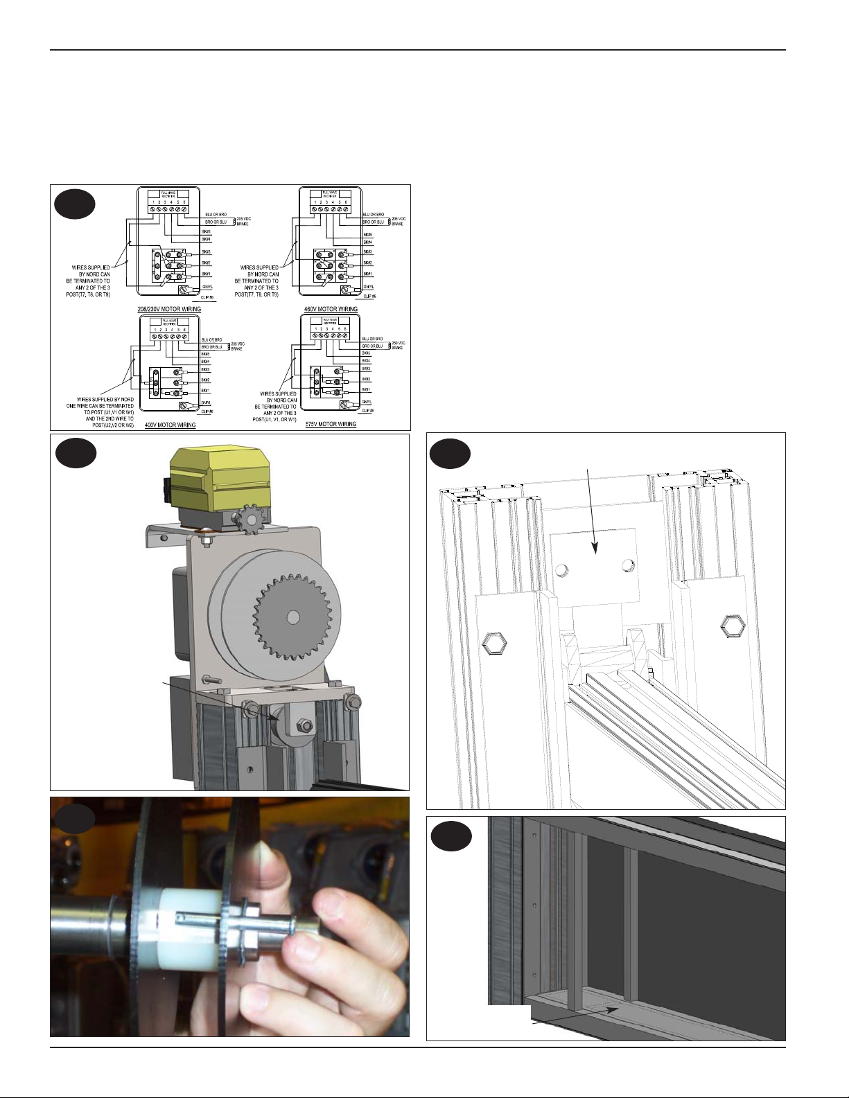
All wiring should be installed by a qualified electrician in
accordance with all national and local electrical codes. If the
rigid conduit is installed, bonding must be maintained between
conduit and ground connections by using ground bushings
and a jumper wire. Solid 3/4” conduit is recommended
IMPORTANT!!!

NOTE: The FLASHFOLD can be installed as a free standing
unit or mounted to a wall or a machine structure in a
machining, welding type of environment:
1. Which workstation will I be working at and which side of
the workstation is the unit to be located?
2. Check that floor is in sound condition, does not have
cracks or flaws and is there anything buried in the floor
where the anchors go?
3. Does the installation allow for clearance for robotic,
machining, welding or other types of operation?
4. Does the installation meet all applicable robotic,
machining, welding or other workstation safety
requirements such as is contained in the following:
a. OSHA Instruction CPL 2-1.24 (Mechanical Power Presses)
b. UL Standard for Safety UL 325 (Door, Drapery, Gate,
Louver and Window Operators and Systems)
c. ANSI RIA R 15.06-1986 (Industrial Robots and Robot
Systems-Safety Requirements)
5. Are any special work permits required?
6. Are there any overhead obstructions?
7. Is a qualified electrician ready to bring in the power and
wire up the controls?
8. Can electrical power to the workstation be shut off without
interfering with other plant operations?
9. Can material handling equipment (forklifts) be detoured
during installation.
10. How will the work area be barricaded?
11. Does the customer wish to be present to observe?
12. Check floor across the width using a long level.
NOTE: The floor must be level so that the header and
curtain container will be level and the header
guides will be plumb.
13. Based on the floor or wall mounting brackets provided,
anchor as follows.
Concrete Floor: Anchors, minimum 3/8” x 2 3/4” [10x70] long.
2”x4” [51x102] Wood Wall Minimum : 3/8” x 1 1/2” [10x38]
Lag screws.
Steel Wall 7ga Minimum:
Weld, 3/8” [10] Tap/Drill, 1/2” [13] Thru Bolt or 1/4”-14 [6]
Self Tap/Drill
Quantity Description
Crate Containing the following
1 Header
2/4 Container Covers
1 Curtain Container
a/r Curtain Container Floor
2 Header Guides
1 Curtain
1 Motor/Brake/Gearbox Assembly w/13’ of cable
1 Motor Mount
1 Drive Shaft Assembly
1 Drive Shroud
1 Control Box w/ Owner’s Manual (optional)
4 Curtain Guides (optional)
1 Reversing Edge (optional)
1 Reversing Edge Chain (optional)
1 Reversing Edge Cable (optional)
1 Interrupt Switch Assembly (optional)
1 Photoeye Assembly (optional)
2/4 Long Side Mounting Brackets (optional)
Parts Box Containing the Following
1 Owners Manual
1 Non-Drive Guide Cap
4 Short Side Mounting Brackets (only if long are
not chosen)
1 Belt Idle (long)
1 Drive Belt (short w/2 loops)
2 Idle Belt Attachment Brackets
2 Idle Belt Attachment Plates
1 Limit Switch Sprocket Large w/Set Screws (2)
1 Chain (#35) Limit Switch (15 3/4”)
1 Limit Switch Chain Link (#35)
1 3/16” x 1/4” x 4 1/2” Key
1 Retaining Ring
4 M8 x 1.25 x 25mm Bolts
4 3/8-16 X 3/4” Bolts
4 3/8” Lock Washers
8 1/4” Lock Washers
20 1/4-20 x 3/4” Hex Head Bolts
20 1/4” “T” Nuts
30 #12-14 x 3/4” Self Tap/Drill Screws
NOTE: Curtain guides are rough placed at this point, and
will need to be set in proper position later.
1. Floor space the size of the unit is required for installation
2. Remove the curtain container from the crate and position
in front of the machine with the bottom braces toward the
weld unit, Figure 3.1.
3. Remove curtain container cover toward weld unit facing up.
4. Remove header guides and position them next to the
curtain container, Figure 3.1. Groove w/o tabs toward the
top on right side. Non-drive side w/Interrupt switch will be
4” [102] longer.
PUB. NO. 1390E APRIL 2014 3
FLASHFOLD™MODEL 1390
INSTALLATION INSTRUCTIONS
Weld
Unit
Curtain Container
Back Side Faces Up
Right Side-Groove
w/o Tabs on Bottom
Front Faces the Floor
Left Side-Groove
w/Tabs on Bottom
When working with electrical or electronic controls, make sure
that the power source has been locked out and tagged according
to OSHA regulations and approved local electrical codes.
WARNING!!!
!
3.1

5. Slide curtain guides into the top of the header guides.
6. Loosen the 1/4” [6] bolts and nuts on the container,
Figure 4.1.
7. Slide the “T” nuts into the groove on the header guides
and place flush with the bottom of the curtain container
and tighten all bolts. In special ordered situations the
curtain container may need to be mounted some pre-
determined distance of the floor, Figures 4.2 & 4.3.
8. Locate the mounting brackets supplied in the parts box,
and assemble brackets to the header guides with the
required 1/4-20 [6] bolts and “T” nuts, Figure 4.4.
9. Attach the belting pressure plate to the idle belt
attachment bracket with the (2) 1/4-20 x 3/4” [6x19] bolts
and lock washers provided, Figure 4.5. Repeat on non-
drive side.
10. Install idle belt attachment bracket on the inside of the
drive header guide flush with the bottom, using two 1/4-20
x 3/4” [6x19] bolts and “T” nuts, Figure 6.
11. Tip both header guides to stand unit up.
HEADER GUIDE INSTALLATION
1. Locate the header and position in front of the machine.
Determine drive and non-drive side, Figure 6.1.
2. Locate the drive (shorter w/2 loops) belt and fasten to the
drive side of the header by removing the center pin on the
bolt, looping belt through and tightening nut.
3. Locate the idle (longer) belt and route through the header
so 2’ [610] hangs out the drive side and the rest out the
non-drive side.
NOTE: To ease belting installation, elevate one end
of the header so the belt slides downhill.
4. Set blocks onto the curtain container frame so the header
can rest on them, Figure 5.2.
4PUB. NO. 1390E APRIL 2014
FLASHFOLD™MODEL 1390
FRAME INSTALLATION
Pre-Installed
1/4” [6] Hex
Bolts with T-Nuts
Slide Header Guide Over T-Nuts
Header Guides Flush with
Bottom of Curtain
Container Unless Specified
Attach belting to idle belting
pressure plate on drive side
Single Outside Floor
Mount Bracket
Floor Mount Bracket for Both
Sides of Header Guides
Brackets may be Turned
90° for Mounting to Wall
or Weld Unit
4.1 4.4
4.2
4.5
4.3

5. Install idle belt attachment bracket to the inside at the top
of the non-drive header guide and fasten the idle belting
to the bracket. Make sure belting is tight and not twisted,
Figure 6.4.
OPTIONAL INTERRUPT SWITCH PLACEMENT
NOTE: The interrupt switch is a cam style switch. It is
at the top of the non-drive curtain guide.
1. Place the curtain in the up position.
2. Adjust position of switch in curtain guide until switch is
aligned with the curtain, Figure 5.4.
3. Secure switch assembly.
4. Wire switch directly into the control circuit, Page 12.
DRIVE SYSTEM INSTALLATION
1. Remove the drive shroud from the mounting plate.
2. Slide the drive mount plate onto the guides with the (4)
1/4-20 x 3/4” [6x19] allen head, “T” nuts. (DO NOT tighten
yet)
3. Fasten the drive mount plate to the top of the header
guides using the (2) 3/8-16 x 3/4” [10x19] hex head bolts
and lock washers. Tighten the 3/8” [10] bolts and then the
previous 1/4” [6] bolts.
PUB. NO. 1390E APRIL 2014 5
FLASHFOLD™MODEL 1390
HEADER INSTALLATION
Header Non-Drive Idle Pulley
Block for header to sit
on curtain container
Install header assembly
in header guides and
lower onto blocks.
Belting Run
Thru Header
(4)- M8 x 1.25 [32]
Bolts & 5/16” [8]
Lock Washers
(2) 3/8” Hex
Head Bolts
w/Lock Washers Snap Ring
5.1
5.2
5.3
5.4
5.5
Frame and Header Installation
Belting
Optional Reversing Edge

4. Install motor assembly onto the drive bracket using (4)
M8-1.25 x 25mm bolts, lock washers and a 13mm socket,
Figure 5.5. Tighten to 230 in-lb [26N-m] torque.
5. Locate pulley shaft assembly and install into gearbox with
the 3/16” x 1/4” x 3 1/2” [8x6x89] key and snap ring
provided, Figure 5.5. Wiring, Figure 6.1.
6. Route the drive belting from the header attachment point
up to the idler pulley onto the backside of the idler pulley,
to the front side of the drive pulley and over the top,
Figure 6.2. Fasten with the 1/4” x 1 3/4” [6x44] clevis pin
provided with 1 1/2 pre-wraps in place, Figure 6.3.
7. Locate the 4” [102] wide black painted steel strip and
place them on the bottom of the curtain container so the
seams fall onto a brace, Figure 6.5.
CURTAIN INSTALLATION
1. Raise the header approximately 3’-4’ [914-1219] off the
floor.
2. Locate and unroll the curtain with windbars pre-installed in
front of the unit with the hook/loop fasteners toward the
unit and the ABS pressure strips away from the unit,
Figure 7.1.
3. If the unit is equipped without a reversing edge, wrap the
curtain around the header and fasten with the hook/loop
fastener.
4. If the unit is equipped with a reversing edge, hook & loop
fasten the curtain to each side of the header.
6PUB. NO. 1390E APRIL 2014
FLASHFOLD™MODEL 1390
DRIVE INSTALLATION
Curtain Container
Steel Strips
Non-Drive Header Guide Idler Pulley/Belting
and Pressure Plate w/ 1/4-20 x 1/2” [6x13] Bolts
Drive Header
Guide Idler Pulley
Belt Routing
Back
Unit
Side
Front Side
6.1
6.4
6.2
6.5
6.3

PUB. NO. 1390E APRIL 2014 7
FLASHFOLD™MODEL 1390
CURTAIN/GUIDE INSTALLATION
Wrap Curtain Around the
Header and use the Hook
and Loop Fastener to
Assemble
If optional curtain guides are
equipped, they are fastened with 1/4-
20 x 3/4” [6x19] bolts and “T” nuts to
all holes on curtain guide to all (4)
pieces. They are installed by lifting to
the top of the sideframe and slid into
the groove. Leave a 1/8” [3] gap
between the end of the curtain guide
and the top of the curtain container
to allow for the front and rear cover
installation. If overhead clearance is
not available, the unit may need to
be tipped down to gain access.
7.1 7.2
7.3
Drive and Curtain Installation
Place the bottom of the curtain into
the bottom of the curtain container
and tek screw the ABS strip, and the
steel strip at the bottom braces on
the frame of the curtain container.
Install the container covers removed
earlier.
Fasten with the #12-14 x 3/4” [19]
self tap/drill screws provided at the
top and bottom of the covers.

8PUB. NO. 1390E APRIL 2014
FLASHFOLD™MODEL 1390
COVER INSTALLATION
Reversing Edge Housing
Reversing Edge
Cable
Reversing Edge
Chain Bracket
Position so the FlashFold
stickers are in the upper
outside corners and the
pinch point sticker is in
the middle at the top.
8.2
8.1
8.4
8.3
Install non-drive
header guide top cap
with (2) 3/8”-16 [10]
hex head bolts.
Place reversing edge on top of curtain bar and
fasten evenly spaced every 12” -18” [305 - 457]
Route reversing edge cable/chain in the groove on
the header guides and fasten with bolt on motor
plate. Chain will curl to the inside of the guide on
right hand motor and opposite on left hand motor.

1. The limit switch is pre-mounted to the top of the motor
mount bracket with the small sprocket attached.
2. Locate the large sprocket, chain and connector in the
parts box.
3. Slide the large sprocket onto the belt pulley shaft and
using a straight edge align with the small sprocket on the
limit switch shaft.
4. For ease of installing chain onto the sprockets allow the
connector link to fall onto the large sprocket, Figure 6.2.
5. Move unit to the near open position.
6. Loosen the two phillips screws and remove cover.
7. Adjust open limit switch by loosening the center screw
and turn the cam locking screw labeled #2 until you hear
the contact click, Figure 9.1.
8. To adjust the closed limit switch, move unit to the near
closed position. Pay attention to rotation of the cam so
when limit is adjusted, it will be on the proper side of the
large cam. Turn the cam locking screw labeled #1 until
you hear the contact click, Figure 9.1.
9. The limit switches are normally closed.
10. For a Right Hand Drive unit, turn the #2 open limit switch
screw clockwise to raise the door and counter-clockwise
to lower the curtain.
11. For a Right Hand Drive unit, turn the #1 close/photoeye
limit switch screw counter-clockwise to raise the curtain
and clockwise to lower the curtain.
12. For a Left Hand Drive unit, turn the #2 open limit switch
screw counter-clockwise to raise the curtain and
clockwise to lower the curtain.
13. For a Left Hand Drive unit, turn the #1 close/photoeye
limit switch screw clockwise to raise the curtain and
counter-clockwise to lower the curtain.
14. Be sure to tighten the center locking screw when
complete.
POWER UP/START UP
1. Assemble components necessary to control 3 phase
power at either 230 or 460 volts.
2. If the curtain goes in the wrong direction, the phase is
reversed. Immediately stop the unit, disconnect power,
lock out and tag power source, and reverse motor leads.
Reconnect power and check operation.
FLASHFOLD™MODEL 1390
PUB. NO. 1390E APRIL 2014 9
LIMIT SWITCH INSTALLATION
Contact Blocks
#1 Close Limit
Switch Screw
#2 Open Limit
Switch Screw
Open Limit
Switch Cam
Close Limit
Switch Cam
Center Adjustment Screw
Contact Block
Wiring Layout
Do not connect or install any activation device until
power up/start up process is completed.
IMPORTANT!!!
9.1
9.2
Cover and Limit Switch Installation
Install drive shroud over
the limit switch and
pulley assembly using
(4) 1/4-20 x 3/4” [6x19]
bolts and (2) “T” nuts.

10 PUB. NO. 1390E APRIL 2014
FLASHFOLD™MODEL 1390
TROUBLESHOOTING
ITEM DESCRIPTION
Brake Check the following concerning the brake:
a) Brake does not release, check connection in junction box.
b) Curtain travels past limit switches, check brake air gap.
Curtain
The curtain provides a barrier against sparks, harmful light emissions and physical contact with the
machine by the operator. The curtain is manufactured of hypalon fire retardant material. Barrier
bars are sewn in to add rigidity. Full width vision or weld screen is available. c
heck the following:
a) Curtain runs in the opposite direction of the button pushed. Check the motor phasing, switch two of
the three lead wires with the power removed.
b) Curtain remains open and does not close, check for activation device failure or activity.
c) Tracks off to the side, check for plumb header guides and a level curtain container.
d) Make sure unit is secured to the floor, wall or structure.
Curtain container The curtain container is the base of the unit and stores the curtain in the open position.
Curtain Guides (optional) The curtain guides, manufactured from an aluminum angle and help guide the curtain in the event
of wind or negative pressure.
Header guides The header guides made of extruded aluminum and are bolted to the curtain container to make up
the units frame.
Interrupt Switch (Optional) The interrupt switch keeps the machine from functioning unless the curtain is in position. The
switch mounts in the bottom of the curtain guide and is activated by the curtain when it comes into
the closed position.
Limit Switch Check the following concerning the limit switches:
a) Curtain does not stop at limit switch, check for loose connections and is limit switch hold down bolt
tight.
b) Check for continuity when the limit is activated.
Motor
The motor assembly includes the motor, gearbox, and brake. The motor assembly lowers the
curtain before the machine cycle begins and raises the curtain back up when the machine cycle is
complete.
Check the following concerning the motor:
Motor will not run, check for loose connections at motor junction box.
Photoeyes
Check the following concerning the optional photoeyes:
a) Make sure nothing is blocking the path of the photoeyes.
b) Check photoeye alignment
Standard Operating Conditions Operate the curtain under normal conditions. Observe the curtain opening to make sure that it
opens fully and does not open so far that it comes out of the curtain guides. Observe the closing
action to make sure that the curtain operates smoothly, and fully closes without excessive curtain
ripple near the bottom.
RITE-HITE MACHINE GUARDING PLANNED MAINTENANCE
Model 1390 FLASHFOLD™
CUSTOMER:
RHC# SERIAL# DATE:
Periodic Cycle Check:
Planned Maintenance
Activation Devices
Chain
Curtain
Electrical Connections
Frame and Hardware
Interrupt Switch (optional)
Labels and Instructions
Limit Switch
Belting
Curtain Basket
Reversing Edge (optional)
Recommended P.M. Intervals
(Time Shown In Months)
1
•
•
Inspect and Perform the Following (See Manual)
Check for proper operation.
The break-in period is 30 days or 50,000 cycles.
Tension must be maintained.
Operate to verify proper operation. Clean with warm
non abrasive soapy water. Check for damage or
wear and repair any tears.
Perform visual inspection and tighten.
Perform visual inspection and tighten. Blow dust
and dirt from the frame assembly.
Verify switch shuts off the proper machine
components when activated.
Replace if missing.
Make sure barrier curtain stops at the proper open
and closed positions. Inspect chain and sprockets
for wear, and lubricate.
Check for wear, proper operation and tension.
Vacuum curtain basket as needed.
Check reversing edge function.
4
•
•
•
•
•
•
•
•
8
•
•
12
•
•
•
•
•
•
•
•
•
•
•
18
•
24
•
•
•
•
•
•
•
•
•
30
•
36
•
•
•
•
•
•
•
•
•
•
•

PUB. NO. 1390E APRIL 2014 11
NOTES PAGE
FLASHFOLD™MODEL 1390
This page intentional left blank.

12 PUB. NO. 1390E APRIL 2014
FIELD WIRING DIAGRAM
FLASHFOLD™MODEL 1390

PUB. NO. 1390E APRIL 2014 13
ELECTRICAL WIRING DIAGRAM
FLASHFOLD™MODEL 1390
Electrical Drawings

14 PUB. NO. 1390E APRIL 2014
CONTROL BOX LAYOUT
FLASHFOLD™MODEL 1390
1
6,24
7,22
6,23
25
19
25
25 26
8,9,10
30,31
2
15,16
5210E031 Rev. C
10/04/2011
Control Box Layout
ITEM QTY DESCRIPTION PART NUMBER
1 1 Control Box Assembly 1746....
2 1 Circuit Breaker, Overload, 1.6-5A 16660008
3 1 Contactor, Interlock, MCS 17000010
4 2 Contactor 24VAC, 16amp, 50/60Hz, 1NO 17000020
5 2 Contactor Auxiliary, 2NO 17000021
6 2 Contact, 3 Across N.O. 17200012
7 1 Contact, 3 Across N.C. 17200013
8 1 Controller, Vital 1, Jokab 17500011
9 1 Controller, Pnoz, Pilz 17500012
10 2 Fuse, .5AMP, 60)V, Time Delay(>= 380V) 51000001
11 1/2 Fuse 1AMP, 250V, Time Delay 51000002
12 1 Fuse Holder, 2 Pole, 600V, 30A 51000003
13 1/2 Fuse Holder, 1 Pole,300V,12A 51000004
14 2 Fuse, 1AMP, 600V, CC, Time Delay (< =240V) 51000023
15 1 Power Supply, Din, 24VDC,18W 65700006
16 1 Relay SPDT 12VAC 10A (Rev Edge only) 66450002
17 1/2 Relay DPDT 24VAC 5A (Stand, Rev Edge or Photoeye option) 66450003
18 1 Relay SPDT 24VAC 10A (photoeye option) 66450004
19 1 Resistor, 200 Ohm, 10 Watt (Rev Edge only) 66550017
20 2/3 Relay Socket 2 Pole (Standard, Rev Edge or Photoeye option) 70350001
21 1 Relay Socket 1 Pole (Photoeye or Rev Edge option) 70350002
22 1 Switch, Push button, Red 22.5MM 72700006
23 1 Switch, Push button, Green 22.5MM 72700085
24 1 Switch, Push button, Yellow 22.5MM 72700086
25 4 Terminal, End, Stop, Screwless 73100024
26 23/25/29 Terminal, PH, Cage, 20A, 3 Hole (2-Photoeye option or 4-Rev Edge) 73100085
27 3 Terminal, PH, Cage, 20A, 3 Hole, Bar 73100086
28 4 Terminal, PH, Cage, 20A, Jump, 2P 73100081
29 2 Terminal, PH, Cage, 20A, 3 Hole, Gnd 73100087
30 1 Transformer 100VA 208/230/460V 24/115V 73550029
31 1 Transformer 100VA 380/415/575V 24/115V 73550030
4
11,13 9
817,20 16,18,21
15,16 15
3
5
29
29

PUB. NO. 1390E APRIL 2014 15
FLASHFOLD™MODEL 1390
SERVICE PARTS
15
17
33
5,6 29
1,2,3
28
16
32
30
36
31
33
37
26
18-20
36
16
7
32
34
24,42
17
17
17
16
7
34
27
44
11
22
23 47
45,46
4
89,10 12
14
13
25
35
41
40 48,49
Service Parts

16 PUB. NO. 1390E APRIL 2014
SERVICE PARTS LIST
FLASHFOLD™MODEL 1390
ITEM QTY DESCRIPTION PART #
1 1 Container, Curtain Ass’y 1721....
(Includes Covers, Floor & HDW)
2 1 Container, Curtain Weldment 1722....
3 a/r Container, Curtain Covers 1873....
4 a/r Container, Curtain Floor 7172....
5 1 Header Ass’y (w/wo rev edge) 5218....
6 1 Header Weldment 5219...
7 2 Header Guides (Ext Hght plus 4 3/8”) 44850144
8 3 Idle Pulley Assembly 65750040
9 1 Reversing Edge 7273....
10 1 Reversing Edge Housing 52930005
11 1 Reversing Edge Cable Carrier Chain 16600022
12 1 Reversing Edge Cable Carrier 14500371
Chain Female Bracket
13 1 Belt, Curtain 1261....
14 1 Belt, Drive 1262....
15 1 Curtain Ass’y (w/wo rev edge) 2853....
16 a/r Curtain Guide 1465....
17 a/r Curtain Barrier Bar 6450....
18 1 Drive Assembly 5530....
19 1 Motor 208/230/460V 55250076
20 1 Motor 575V 55250078
*22 1 Motor Drive Mount Drive 14501000
23 1 Rotary Limit Switch Kit 53700227
24 1 Sprocket Drive (on drive shaft) 70800013
25 1 Sprocket Driven (on limit shaft) 70800012
ITEM QTY DESCRIPTION PART #
26 1 Shroud Drive Pulley Guard 69200090
27 1 Retaining Ring 67020016
28 1.427’ Chain Drive #35 16600019
29 1 Chain Connector Link #35 54400008
*30 1 Drive Pulley Assembly 53700365
31 1 Interrupt Switch 53700362
32 0/2/4 Mounting Bracket Long Side 14500729
33 4 Mounting Bracket Short Side 14500728
34 2 Bracket, Idle Belt Attachment 14500734
35 1 Header Guide, Non-Drive Top Cap 65000368
36 2 Plate Belt Attachment 65000367
37 a/r Kit, Photoeye 53700366
38 8 Washer, Lock, 1/4” 74110004
39 4 Screw, 1/4-20 x 1/2” 67860002
40 2 Screw, 3/8-16 x 3/4” 67880008
41 10 Screw, Self Tap/Drill, #12-14 x 3/4” 67850004
42 2 Screw, Set, 1/4-20 x 1/4“ 67860038
43 -
44 1 Nut, Lock, 1/4” 55610001
45 a/r Nut, T, 1/4-20 55610017
46 4 Screw, 1/4-20 x 3/4” 67860003
47 4 Screw, M8-1.25 x 30mm 67930029
48 1 Rectifier, Bridge, 230/460V 66270009
49 1 Rectifier, Bridge, 575V 66270012
* If date < 12/12/2011, then use # 30.

PUB. NO. 1390E APRIL 2014 17
ARCHITECTURAL DRAWING
FLASHFOLD™MODEL 1390
Architectural Drawings

18 PUB. NO. 1390E APRIL 2014
NOTES PAGE
FLASHFOLD™MODEL 1390
This page intentional left blank.

PUB. NO. 1390E APRIL 2014 19
NOTES PAGE
FLASHFOLD™MODEL 1390
This page intentional left blank.

20 PUB. NO. 1390E APRIL 2014
RITE-HITE MACHINE GUARDING WARRANTY
FLASHFOLD™MODEL 1390
LIMITED WARRANTY
RITE-HITE Company, LLC and its affiliates (collectively “RITE-HITE”) warrants that the FlashFold unit sold to the Owner will be free of defects in
design, materials and workmanship (ordinary wear and tear excepted) for the periods set forth below (“Limited Warranty”).
One (1) Year on all mechanical and electrical parts.
One (1) Year labor, based on approved travel and labor repair times.
REMEDIES
Parts. RITE-HITE’s obligations under this Limited Warranty is limited to repairing or replacing, at RITE-HITE’s option, any part which is determined
by RITE-HITE to be defective during the applicable warranty period. Such repair or replacement shall be RITE-HITE’s sole obligation and the
Owner’s exclusive remedy under this Limited Warranty.
Labor. RITE-HITE will provide warranty service without charge for labor in the first year of the warranty period. Thereafter, a charge will apply to any
repair or replacement under this Limited Warranty.
CLAIMS. Claims under this Limited Warranty must be made (i) within 30 (thirty) days after discovery and (ii) prior to expiration of the applicable
warranty period. Claims shall be made in writing or by contacting the representative from whom the Product was purchased directly. Owner must
allow RITE-HITE or its agent, a reasonable opportunity to inspect any Product claimed to be defective and shall, at RITE-HITE’s option, either (x)
grant RITE-HITE or its agent access to Owner’s premises for the purpose of repairing or replacing the Product or (y) return of the Product to the
RITE-HITE, f.o.b. RITE-HITE’s factory.
NOT WARRANTED. RITE-HITE does not warrant against and is not responsible for wear items such as fuses, batteries, bulbs, vision and seals.
No implied warranty shall be deemed to cover, damages that result directly or indirectly from: (i) the unauthorized modification or repair of the
Product, (ii) damage due to misuse, neglect, accident, failure to provide necessary maintenance, or normal wear and tear of the Product, (iii) failure
to follow RITE-HITE’s instructions for installation, failure to operate the Product within the Product’s rated capacities and/or specified design
parameters, or failure to properly maintain the Product, (iv) use of the Product in a manner that is inconsistent with RITE-HITE’s guidelines or local
building codes, (v) movement, settling, distortion, or collapse of the ground, or of improvements to which the Products are affixed, (vi) fire, flood,
earthquake, elements of nature or acts of God, riots, civil disorder, war, or any other cause beyond the reasonable control of RITE-HITE, (vii)
improper handling, storage, abuse, or neglect of the Product by Owner or by any third party.
DISCLAIMERS. THIS LIMITED WARRANTY IS EXCLUSIVE AND IN LIEU OF ALL OTHER REPRESENTATIONS AND WARRANTIES, EXPRESS
OR IMPLIED, AND RITE-HITE EXPRESSLY DISCLAIMS AND EXCLUDES ANY IMPLIED WARRANTIES OF MERCHANTABILITY OR FITNESS
FOR PURPOSE. RITE-HITE SHALL NOT BE SUBJECT TO ANY OTHER OBLIGATIONS OR LIABILITIES, WHETHER ARISING OUT OF BREACH
OF CONTRACT, WARRANTY, TORT (INCLUDING NEGLIGENCE AND STRICT LIABILITY) OR OTHER THEORIES OF LAW, WITH RESPECT TO
THE PRODUCTS SOLD OR SERVICES RENDERED BY RITE-HITE, OR ANY UNDERTAKINGS, ACTS, OR OMISSIONS RELATING THERETO.
LIMITATION OF LIABILITY. IN NO EVENT SHALL RITE-HITE BE RESPONSIBLE FOR, OR LIABLE TO ANYONE FOR, SPECIAL, INDIRECT,
COLLATERAL, PUNITIVE, INCIDENTAL, OR CONSEQUENTIAL DAMAGES, EVEN IF RITE-HITE HAS BEEN ADVISED OF THE POSSIBILITY OF
SUCH DAMAGES. Such excluded damages include, but are not limited to, personal injury, damage to property, loss of goodwill, loss of profits, loss
of use, cost of cover with any substitute product, interruption of business, or other similar indirect financial loss. Rite-Hite 2.1.14
RITE-HITE DOORS, INC. is covered by one or more of the following U.S. patents, including patents applied for, pending, or issued:
5,579,820, 5,638,883, 5,794,678, 5,887,385, 5,915,448, 5,944,086, 6,089,305, 6,145,571, 6,148,897, 6,192,960, 6,212,826, 6,321,822, 6,325,195,
6,330,763, 6,360,487, 6,481,487, 6,560,927, 6,598,648, 6,612,357, 6,615,898, 6,688,374, 6,698,490, 6,837,296, 6,901,703, 6,942,000, 6,964,289,
7,034,682, 7,045,764, 7,111,661, 7,114,753, 7,151,450, 7,578,097, 7,699,089, 7,748,431, 7,757,437, 8,037,921, 8,167,020, 8113265.
RITE-HITE®, RITE-HITE®DOORS, RITE-HITE® MACHINE GUARDING, DEFENDER™, FLASHFOLD™, VERTIGUARD™, SLIDEAIR™,
ROLLSHILED™, ROLLTOP™ are trademarks of RITE-HITE®.
RITE-HITE MACHINE GUARDING
4343 Chavenelle Drive
P.O. Box 1200
Dubuque, Iowa 52002-2654
Toll Free Sales: 800-553-5560
Sales: 563-589-4401
Sales Fax: 563-589-2776
Service: 563-589-2722
Service Fax: 563-589-2737
Representatives in All Major Cities
www.frommeltsafety.com
www.ritehite.com
Table of contents
Other RITE-HITE Industrial Equipment manuals
Popular Industrial Equipment manuals by other brands

HEIDENHAIN
HEIDENHAIN VM 182 operating instructions

BOCI
BOCI BLT6102H product manual

ermengineering
ermengineering AFP-200 Use and maintenance manual

Hoshizaki
Hoshizaki Upright Series quick start guide

Matsing
Matsing MS-MBA-3-F4A3 instruction manual

James Walker
James Walker KlickFix On-site Refurbishment Guide