RITE-HITE Eclipse 620G User manual

Eclipse®Dock Shelter
(620G, 620NH)
Installation/Service/Owner's Manual
Document Name: 620G0001
Illustration Name: 620G0002
Manual Part #: 39500129
Model #: 620G, 620NH
Publication: AMEN00141 2019-11-22
NOTICE TO USER . . . . . . . . . . . . . . . . . . .2
SAFETY. . . . . . . . . . . . . . . . . . . . . . . . . . . .3
INSTALLATION
Overview. . . . . . . . . . . . . . . . . . . . . . . . . . . 4
Preparation. . . . . . . . . . . . . . . . . . . . . . . . . 5
Mounting Methods . . . . . . . . . . . . . . . . . . . 5
Side Frames . . . . . . . . . . . . . . . . . . . . . . . . 6
Canopy Header . . . . . . . . . . . . . . . . . . . . . 8
Side Curtains . . . . . . . . . . . . . . . . . . . . . . 12
Weighted Seal, Wear Panel . . . . . . . . . . . 13
Bumpers . . . . . . . . . . . . . . . . . . . . . . . . . . 17
Collapsible Style Draft Pad. . . . . . . . . . . . 17
MAINTENANCE . . . . . . . . . . . . . . . . . . . .19
PARTS
Exploded View – 620G. . . . . . . . . . . . . . . 20
Exploded View – 620NH. . . . . . . . . . . . . . 22
WARRANTY . . . . . . . . . . . . . . . . . . . . . . .24

Eclipse®Dock Shelter (620G, 620NH) Installation/Service/Owner's Manual Rite‑Hite®
2Publication: AMEN00141 2019-11-22
NOTICE TO USER
Thank you for purchasing a Rite‑Hite product.
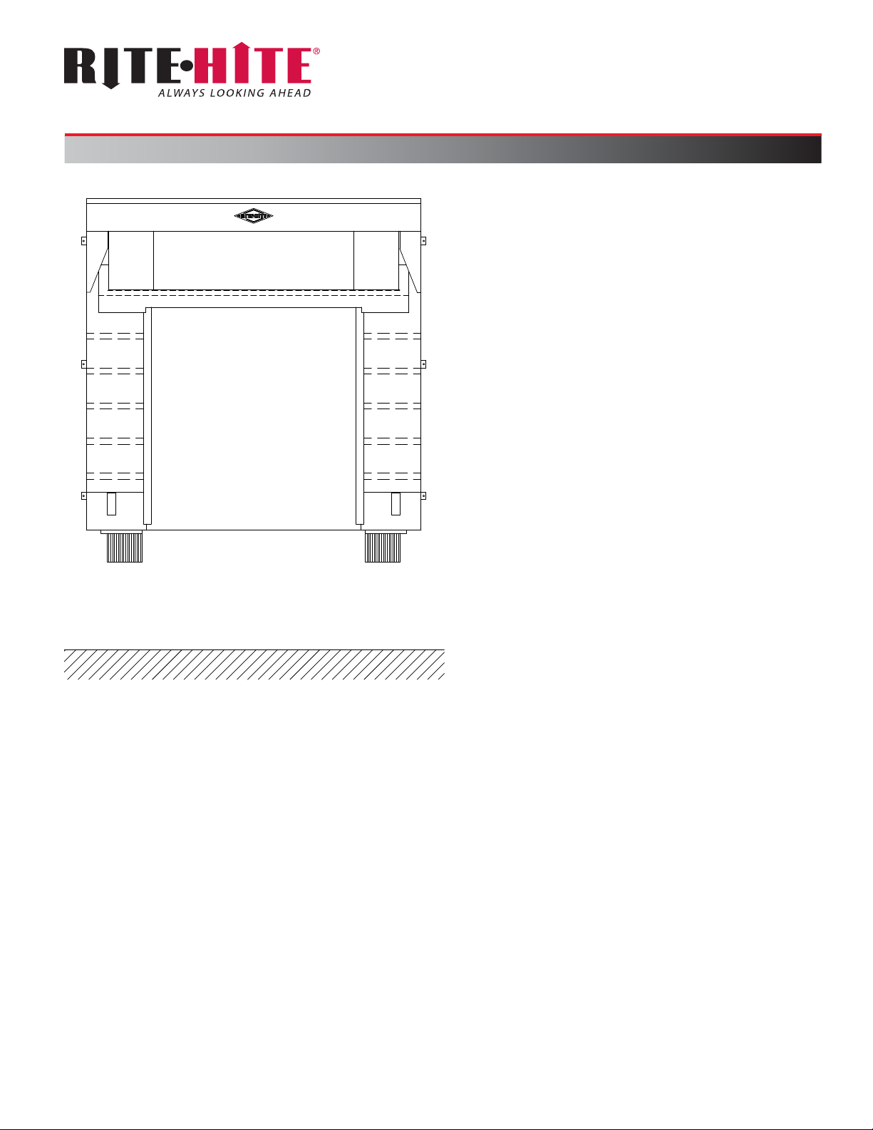
The Eclipse®620G and 620NH Dock Shelters provide a
durable, eective environmental seal between the trailer
and building.
Instructions apply to both 620G and 620NH unless
otherwise noted.
The English version of this manual shall prevail over any
error in, or conicting interpretation of, any translations.
Rite‑Hite reserves the right to substitute and/or modify
parts and drawings. If separate prints are included with
the unit, they supersede the manual.
For best results, have this product serviced by an
authorized Rite‑Hite representative.
A Planned Maintenance Program (P.M.P.), customized to
your specic operation is available and recommended.
For a P.M.P., contact your local Rite‑Hite representative
or Rite‑Hite technical support at (U.S.) 1‑888‑456‑3625,
(S.A.) +55 21 99616 4421.
The Rite‑Hite products in this manual are covered by one or more of the
following U.S. patents: 6014844, 6044597, 6205721, 6233885, 7146673,
7185463, 7246467, 7287353, 7584517, 7695048, 7757442, 7877831,
7882663, 8042307, 8141305, 8156995, 8307588, 8327587, 8353136,
8458960, 8495838, 8540007, 8752335, 8800086, 8839842, 8887447,
8915029, 8943630, 8991467, 9003724, 9003725, 9010039, 9079713,
9162832, 9170044, 9187271, 9193543 9534372, 9534373, 9551181,
9592972, 9624049, 9751703, 9797127, 9797128 and may be covered
by additional pending U.S. and foreign patent applications.
Manufactured by Rite‑Hite Environmental Enclosure Corporation.

Rite‑Hite®Installation/Service/Owner's Manual Eclipse®Dock Shelter (620G, 620NH)
Publication: AMEN00141 2019-11-22 3
SAFETY
Safety Identifications
DANGER
Indicates a hazardous situation which, if not
avoided, will result in death or serious injury.
WARNING
Indicates a hazardous situation which, if not
avoided, could result in death or serious injury.
CAUTION
Indicates a hazardous situation which, if not
avoided, could result in minor or moderate injury.
NOTICE
Indicates a situation which can cause damage to the
equipment, personal property and/or the environment,
or cause the equipment to operate improperly.
NOTE:A note is used to inform you of important
installation, operation, or maintenance information.
Lockout Procedure
Barricade work area and post safety warnings.
Power supply and control must:
• Be disconnected or locked in OFF position
using a lockout device approved by local
codes.
• Have signage that;
−Clearly states repairs are being made.
− Identies person responsible for lockout condition.
NOTE:Only this person should be able to remove
warnings and lockout device.
−Withstands environmental conditions (weather,
wet, and damp, etc.) and remains readable.
General
WARNING
To prevent unauthorized use, barricade the work
area at dock and ground level while service work
is being performed.
190820

Eclipse®Dock Shelter (620G, 620NH) Installation/Service/Owner's Manual Rite‑Hite®
4Publication: AMEN00141 2019-11-22
INSTALLATION
Overview
1. Unpack and inspect unit.
2. Install side frames and bracket anchors.
3. Install side arms, front bar and canopy top.
4. Install side curtains and pocket straps.
5. Install gutter, roller seal, and wear panels.
6. Install draft pads.
Instructions assume that the installer is outside the building facing the loading dock.
Figure 1

Rite‑Hite®Installation/Service/Owner's Manual Eclipse®Dock Shelter (620G, 620NH)
Publication: AMEN00141 2019-11-22 5
INSTALLATION
Preparation
Verify all components were received. Notify your Rite‑Hite
Representative if parts are missing or damaged.
Mounting Methods
NOTE:Any additional fasteners, backer plates and
materials for additional structure are supplied by others.
Concrete Block or Brick Wall
Through bolt fastening is required.
• Bore a hole through the building wall.
• Use a 3/8in [9mm] diameter threaded rod with
a washer, nut, and jam nut on each end.
• Install a backer plate inside the building wall when
the wall will not support the bolt.
Concrete Tilt-Up Walls (Precast)
Use 3/8in [9mm] lag bolts with expansion shields,
3/8in [9mm] 1 piece anchor bolts with expansion collar, or
equivalent fastener.
If building wall is too thin to eectively hold the lag bolt or
anchor bolt, through bolt method of attachment is required.
NOTE:To determine anchor length, use anchor
manufacturer’s recommendation for minimum anchor
embedment.
Metal Sided Building
Through bolt fastening is required.
• Use a 3/8in [9mm] diameter bolt with a washer and
lock nut to fasten the unit to the structural member of
the building or to the backer plates. If necessary, use a
3/8in [9mm] diameter threaded rod with a washer and
lock nut on each end.
• Install a backer plate that is fastened directly to
structural member when it is not possible to fasten
directly to structural building members.
NOTE:See "Figure 2" for recommendations.
Uninsulated Wall Building
Building Structural Member
Filler Boards*
Min. 3/8in Fasteners*
Corrugated
Metal Siding
Head Frame
2x6 or Structural Steel Channel Backer
Angle Bracket*
Insulated Wall Building
Building Structural Member
Angle Bracket*
2x6 or Structural Steel Channel Backer*
Insulation
Filler Boards*
Head Frame
Pipe Spacers*
Corrugated
Metal Siding
Min. 3/8in Fasteners*
*Supplied by others.
Figure 2

Eclipse®Dock Shelter (620G, 620NH) Installation/Service/Owner's Manual Rite‑Hite®
6Publication: AMEN00141 2019-11-22
INSTALLATION
Side Frames
D
G
F
E
H
J
J
B
C
A
1. Before mounting side frames, install canopy mounting
brackets (A) to top of side frames (B).
• Position bracket so notches at top of bracket are
ush with the top of the wood, side pad backer (C).
• Secure in place with 6 hex head wood screws (J)
provided.
NOTE:Brackets (A) are not part of the overall unit
width. Unit width when mounting side frames should
be measured from outside edge of side frames.
Brackets add ≈ 1/4in [6mm] to unit's overall footprint.
Allowance is accounted for in the header installation.
2. Measure and mark:
• Measure dock door opening width (D). Divide in
half and mark the centerline of the opening at
dock level (E).
• Measure unit width and divide in half. Compare to
PAF (Product Application Form) specs.
• Measure from door centerline (E) to half of the head
frame dimension (F) and mark the outside wall (at
the bottom of the door opening or at dock level).
This mark is for the outside edge of the side frame.
• Measure (at dock level) from this mark (outside
edge of the side frame) across the door opening to
the unit width (G). Mark this measurement for the
outside edge of the second side frame.
• Consult PAF or sales representative for mounting
height to the bottom of the side pads (H). Measure
up from grade on the dock face and mark.
NOTE:Typically, the bottom of the side pad is
mounted at dock height. Some applications may
require mounting them at a dierent location.
Example: When dock bumpers are mounted
above dock height or above the pit oor (on vertical
leveler applications) it may be required to mount
the bottom of the side pads/side frames at a height
even with the top of the bumpers.
3. Dry fit and shim:
• Using carpenter’s level, plumb up the wall the height
of the side frame and mark the outside edges of the
side frames on the wall at top.
• Measure full width, etc. Using a plumb bob or
carpenter’s level make sure that the outside wall
is plumb from the highest point on the side frame
location to dock level.
• Shim side frames as required.
Figure 3

Rite‑Hite®Installation/Service/Owner's Manual Eclipse®Dock Shelter (620G, 620NH)
Publication: AMEN00141 2019-11-22 7
INSTALLATION
Side Frames Continued
Flush Mounting
Flush Mount
Bracket
Oset =
‑1/4in [‑6mm] to
1/4in [6mm]
‘L’ Bracket
Oset Mounting
‘L’ Bracket
Bent
‘L’ Bracket
Oset =
1/2in to 3 1/2in
[13mm ‑ 89mm]
‘L’ Bracket
‘L’ Bracket Oset =
4in [102mm] or
Greater
9in
[225mm] max.
Equal
9in
[225mm] max.
Equal
4. Install brackets:
NOTE:
– Side frames are supplied with brackets that
match the application (Figure 4).
– If blockouts were supplied with the unit,
reference the blockout installation manual
(Document 1321‑0008) and this manual to
ensure proper installation of the blockouts and
the side frames.
• Position the side frames on their marks.
• Mark the side frame for bracket installation (3 on
each side of each side pad) (Figure 5).
Example: Line up the mounting hole on the
bracket with a mortar joint on the wall and attach
the mounting bracket to the side frame backer
board.
• Attach the brackets to the side frame backer. Use
(supplied) 1/4in x 1 1/4in wood screws for wood
backers.
NOTICE
4in [102mm] width side frames require protective
bumpers to be installed below the side pads.
Reference "Bumpers" on page 17.
If the 4in [102mm] side frame (including blockout) has
an overall projection greater than 40in [1016mm], the
bottom, front of the blockout must be secured to either
the bumpers, the building foundation, or any other
solid rigid structure underneath the blockout. This is
required to stabilize the side frames.
5. Attach the side frames to the building wall, ensuring
they are aligned with the marks made in step 1.
NOTICE
It is critical to mount the side frames plumb and per
the building style (Mounting Methods, page 5).
Figure 4
Figure 5

Eclipse®Dock Shelter (620G, 620NH) Installation/Service/Owner's Manual Rite‑Hite®
8Publication: AMEN00141 2019-11-22
INSTALLATION
Canopy Header
NOTE:Installation procedure is the same for Standard
Pitch and Integral Hood, except that the canopy mounting
bracket is longer for the Integral Hood.
Side View
A
Bracket for Reference Only
Side Arm
Front Bar
1. Attach the side arms to the front bar. Before inserting
the attachment bolts, confirm orientation of the side
arms is correct (A).
C
B
2. Lift the side arm/front bar assembly together and
position across the installed side frames and
mounting brackets. Position it on top so the side arms
on the top frame are facing the wall and land between
the mounting brackets on side frames (Figure 7).
3. Connect bracket and side arm with bolt (B) on each
side of unit. Secure with (supplied) nylock nut (C).
D
E
4. Install the installation chains on both sides of the
canopy frame. The chains hold the front bar up so the
canopy cover can be attached.
• First attach quick link side (D) of the chains to the
inside legs of the canopy mounting brackets.
• Next, lift up canopy front bar and attach the "S" hook
side (E) of the chains to holes on the inside face of
the side arms.
Figure 6
Figure 7
Figure 8

Rite‑Hite®Installation/Service/Owner's Manual Eclipse®Dock Shelter (620G, 620NH)
Publication: AMEN00141 2019-11-22 9
INSTALLATION
Canopy Header Continued
Endcap Endcap
5. Unroll and then lift and lay the canopy cover (top bar
attached) on top of the side arms at the wall.
Lift up and slowly position the top bar behind the tabs
on the canopy mounting brackets.
Make sure the top bar is oriented correctly.
• All 4 faces of top bar should be covered with fabric.
• Fabric should be wrapped from front face of top bar,
under the bottom, up the back (against the wall),
across the top towards the front of the unit, then
extend from the top, front corner of the top bar down
to the front bar.
• The canopy cover and end caps (at the corners
where the canopy top and end cap meet) are laying
correctly over the edge of the mounting bracket.
6. Drape canopy cover over the front bar (the
2 1/2in [65mm] square tubing). Make sure the canopy
cover at the front corners lays correctly over the
corners of the front bar.
Side View
Part of End Cap
Removed for Clarity
Pocket with Poly
Notch
7. Wrap the canopy cover front bar pocket (with poly strip
inside), down and around the bottom of the front bar.
• The pocket/poly strip will wrap back up the back
inside face of the front bar and tuck behind the steel
angle welded at back.
• The pocket is notched to t around the side arm
bracket and the edge of the pocket should line up
with the edge of the steel angle on both ends about
1/2in [13mm] away from the side arm bracket. Make
sure that the pocket/poly strip combination gets
seated all the way down in the space between angle
and front bar.
Figure 9
Figure 10

Eclipse®Dock Shelter (620G, 620NH) Installation/Service/Owner's Manual Rite‑Hite®
10 Publication: AMEN00141 2019-11-22
INSTALLATION
Canopy Header Continued
WARNING
The canopy header is a self supporting unit.
Installing less than 6 anchors and/or insucient
anchor installation methods is dangerous and can
cause unit failure.
Metal sided buildings require special and
increased mounting support considerations.
1 anchor location is required into solid structure
(H) (Figure 11) on each side of the door opening.
All other mounting locations require a backer
plate and pipe spacers (as needed) on the inside
of the wall so the mounting bar and the wall will
ex together.
• If structure is not aligned with 1 of the
pre-drilled mounting holes. Drill new hole
which will replace the nearest pre-drilled
mounting hole.
• If no structure is existing in this area, it must
be added at the outermost pre-drilled mounting
hole, directly above the side pad. All other
locations require a backer plate and pipe
spacers (as needed).
G
F
H
Endcap
Drill
Side View
8. Review "Mounting Methods" on page 5.
9. Position top bar in brackets (F). Top bar must be
secured to building in 6 locations (G).
Top bar is pre‑drilled, but other holes may be drilled
in place of these in order to line up with building
structure or to avoid obstacles.
Figure 11

Rite‑Hite®Installation/Service/Owner's Manual Eclipse®Dock Shelter (620G, 620NH)
Publication: AMEN00141 2019-11-22 11
10. After all the anchors are installed and tightened and
the poly strip is seated properly at the back of the
front bar, release the safety chains at the "S" hook
locations (E) (Figure 8, page 8), and slowly lower
the front bar to apply tension to the canopy cover.
11. When the front bar is self supporting, check the
locations of the canopy cover's corners. Make sure
there are no hang ups of fabric. The corners must fit
properly so heavy loads (e.g. snow, ice) do not tear
the canopy fabric.
After the corners are correct, bounce the header up
and down slightly by pushing up on the front bar a
maximum of about 1/2in [13mm]. This helps pull the
fabric in the pocket around the front bar.
I
Front Bar
Height O Grade
12. Measure height to bottom of front bar off grade and
compare to value in the PAF. If the front bar needs to
be raised, adjust the pin location (I) in the pivot arm
extension.
NOTE:Typically, the bottom of the front bar is at least
12in [305mm] higher than the tallest trailer height.
Each hole raises the front bar height ≈ 2 1/4in [206mm]
compared to the adjacent hole.
13. Caulk along the entire edge of the canopy top at the
building wall, making sure the ends are covered.
Use a exible caulk (appropriate for the conditions
and materials/surfaces being joined).
14. Pull the canopy cover end caps (located at each end)
down to cover the side frame.
Attach the end cap to the side frame backer using one
of the screws holding on the mounting bracket.
NOTE:Attach the touch and hold fastener tab at the
bottom, inside of the end cap to the mating touch and
hold fastener near the front of the side pad. Secure so
the end cap continues to lay at and unwrinkled.
After side curtain installation, this tab will end up being
clamped between the touch and hold fasteners on the
side pad and the side curtain.
Figure 12
INSTALLATION
Canopy Header Continued

Eclipse®Dock Shelter (620G, 620NH) Installation/Service/Owner's Manual Rite‑Hite®
12 Publication: AMEN00141 2019-11-22
INSTALLATION
Side Curtains
NOTE:620NH side curtain shown. Installation of 620G
side curtain is identical.
NOTE:Always align outside touch and hold fastener
ap (A1, A2) rst.
B
A1
A2
Top View
A1, A2 B
1. Position top edge of side curtain approximately
1in [25mm] above the top edge of the side frame
and secure in place by pressing the touch and hold
fastener on the outside mounting flap (A1) to the
mating touch and hold fastener on the outside of the
side frames (A2).
NOTE:When attaching the side curtain at the top,
DO NOT let the weight of the side curtain hang on the
side frame until at least 24in [610mm] of the touch and
hold fastener is connected.
2. Make sure that the mounting flap on the outside of
the side curtain completely covers and is properly
aligned with the touch and hold fastener on the side
frame.
3. Continue to align the mounting flap to the outside of
the side frame touch and hold fastener and continue
working downward to the bottom of the side frame.
Keep continuous downward pressure on side curtain
to avoid wrinkles in fabric.
4. Starting at the top, repeat Steps 1 and 2, with the
inside mounting flap (B). The side curtain must be
perpendicular to the side frame when finished.
C
5. Attach the side curtain pocket to the canopy
installation chain (C).
• First, run the “S” hook link part of the chain through
the loop on the pocket located at the top, backside
of the side curtain.
• Run the chain coming in the loop from the top. Pull
the chain just short of putting tension on the pocket.
• Take the “S” hook link and hook back onto the chain.
Make sure chain is not tangled. “S” link does not
have to be closed, but can be if desired.
Do this for both sides.
Figure 13
Figure 14

Rite‑Hite®Installation/Service/Owner's Manual Eclipse®Dock Shelter (620G, 620NH)
Publication: AMEN00141 2019-11-22 13
INSTALLATION
Weighted Seal, Wear Panel
Position Roller Seal Assembly
<Eclipse Manual ‑ Roller Seal_191004.pdf>
A
E
Roller Seal Assembly
Canopy Top
B
D
C
NOTE:Canopy removed for clarity.
1. Position roller seal assembly so that center tabs (A)
and top edges are aligned the full width (B) with the
canopy top.
2. Tuck roller seal ends behind canopy end caps (C).
3. Connect strap to ring at back of the header (D)
(on both sides).
NOTE:No windstraps are used on the bottom of the
roller seal assembly (E).
Figure 15

Eclipse®Dock Shelter (620G, 620NH) Installation/Service/Owner's Manual Rite‑Hite®
14 Publication: AMEN00141 2019-11-22
INSTALLATION
Weighted Seal, Wear Panel Continued
Secure Roller Seal Assembly
<Secure Roller Seal Assembly_adj.pdf>
B
A1
A2
C
D
Canopy Top
E
1. Insert gutter panels (A1, A2) in pocket (B) located
behind 4in [102mm] touch and hold fastener on
weighted seal.
Slide 1 HMWPE panel right (A1) and 1 HMWPE panel
left (A2) to ll entire width of pocket.
2. Secure seal assembly and gutter panel to front bar
in 6 places with 1 1/4in [30mm] long self drill/tap
screws (C).
• Do not use washers with these 6 fasteners.
• Align fasteners with tabs (D) on top edge of fabric
ap (E).
• Do not put screw at center location.
Figure 16

Rite‑Hite®Installation/Service/Owner's Manual Eclipse®Dock Shelter (620G, 620NH)
Publication: AMEN00141 2019-11-22 15
INSTALLATION
Weighted Seal, Wear Panel Continued
Position Wear Panels on Head Frame
B
C
Align inside edge of
(A) with outside of
center foam block.
A
A
≈ 4in
[100mm]
overlap
Flap
<Eclipse Manual ‑ Wear Panels_191004.pdf>
1/2in [13mm] MAX.
Side View
Roller Seal Assembly
Corner Wear Panel
Center Wear Panel
Assembly
Washer
Fastener
Gutter Panel Assembly
Gutter Flap (Shown Up)
Front Bar
1. Align top edges of corner and center panels with top
of touch and hold fasteners on the canopy (C).
• Position both corner panels (A).
• Center wear panel assembly (B) on
center of unit width.
Figure 17

Eclipse®Dock Shelter (620G, 620NH) Installation/Service/Owner's Manual Rite‑Hite®
16 Publication: AMEN00141 2019-11-22
INSTALLATION
Weighted Seal, Wear Panel Continued
Secure Wear Panels, Front Flaps and Gutter Flap
<Eclipse Manual ‑ Secure wear panels_191004.pdf>
A
Secure each front ap:
(2) 1‑1/4in self drill/tap screws
with washers
Secure each corner wear panel (inside screw goes
through center wear panel assembly and corner
wear panel):
(3) 2in self drill/tap screws with washers
Secure center wear panel assembly. Align screws
with fabric tabs on top edge of fabric:
(3) 2in self drill/tap screws with washers
Front Flap
1. Install fasteners (Figure 18).
2. Fold over gutter flap (A) and secure touch and hold
fastener.
Figure 18

Rite‑Hite®Installation/Service/Owner's Manual Eclipse®Dock Shelter (620G, 620NH)
Publication: AMEN00141 2019-11-22 17
INSTALLATION
Bumpers
1in ‑ 2in [25mm ‑ 50mm]
below dock level
1. Mount 1 bumper per side frame to the foundation wall.
2. Position bumpers so they are centered with the side
frames, and located 1in ‑ 2in [25mm ‑ 50mm] below
dock level.
3. Fasten the bumpers to the building’s foundation
wall. Use a 1/2in lag bolt with expansion shields,
1/2in 1 piece anchor bolts with expansion collar, or
equivalent fastener. 4 anchors per bumper (required).
Collapsible Style Draft Pad
B
D
C
D
A2 A1
1. Open attachment flap(s) on side member (A1)
and back of side curtain (A2).
2. Align the draft pad's top edges to the center stitch
lines on the attachment flaps (B). Press into place on
touch and hold fasteners.
3. Flip down the upper flap(s) so they lay over the touch
and hold fastener on the draft pad. The draft pad
should fit exactly between the building wall and the
back side of the side curtain (C).
4. Press firmly to attach.
5. Install 2 fasteners through the grommets into the
backer board (or blockout) on the side frame (D).
Figure 19
Figure 20

Eclipse®Dock Shelter (620G, 620NH) Installation/Service/Owner's Manual Rite‑Hite®
18 Publication: AMEN00141 2019-11-22

Rite‑Hite®Installation/Service/Owner's Manual Eclipse®Dock Shelter (620G, 620NH)
Publication: AMEN00141 2019-11-22 19
MAINTENANCE
Before use, inspect all parts for damage. Repair and
replace as required.
Clean/wash unit with a low pressure hose or damp cloth.
Keep unit free of snow and ice. Metal hoods are
recommended to protect seals and shelters from rain and
snow at docks without protective building projections
and/or canopies.

Eclipse®Dock Shelter (620G, 620NH) Installation/Service/Owner's Manual Rite‑Hite®
20 Publication: AMEN00141 2019-11-22
PARTS
Exploded View – 620G
<Eclipse Manual ‑ 620G Exploded Diagram_191004.pdf>
This manual suits for next models
1
Table of contents