Ritron Liberty RLR-460 User manual

Model: RLR-460 and RLR-465
UHF Analog Liberty Repeater, 2 Watt and 5 Watt, 12.5kHz
ALIGNMENT AND DUPLEXER TUNING INSTRUCTIONS
FOR USE BY AUTHORIZED SERVICE/MAINTENANCE PERSONNEL ONLY
Ritron Pub: RLR-460/465-ALIGN 01/21
© 2021 Ritron, Inc. All rights reserved.
Ritron, Inc. is a registered trademarks of Ritron, Inc.
Call 800-USA-1-USA
For the right Wireless Solutions for your communication needs.
505 West Carmel Drive, Carmel, Indiana 46082-1998 · Ph: 317-846-1201 · Fax: 317-846-4978
Have questions? Call 800-USA-1-USA (800-872-1872) or visit our website at www.ritron.com

DISASSEMBLY
Remove the power and interface connectors before disassembling the unit. The unit is disassembled for alignment/service
by removing the six T-10 torx screws from the end plate with the antenna connector as indicated by the white arrows. The
cover with the other end plate is then slid off.
DUPLEXER
The duplexer allows the Repeater to simultaneously transmit and receive. To accomplish this, the receive input path must
suppress(notch) the transmitter signal by 65dB or more. In addition, on the transmit path, transmitter noise on the receive
frequency must be also suppressed by about 65dB. The duplexer contains four cavities, two for each path to achieve the
necessary notch depth. Because the notches are very narrow, the duplexer must be re-tuned if the frequency of
operation is changed by more than 50 kHz. Follow the procedure below to tune the duplexer:
1. Unplug the two RF cables connecting the duplexer to the main PCB.
2. View video in the attached link for Duplexer Tuning Instructions.
Instructions for Freedom R8100: https://www.youtube.com/watch?v=V16Wz8JfJ1U
Instructions for Aeroflex 3920: https://www.youtube.com/watch?v=jaCaCWUDI5s
Generic Tuning Instructions: https://www.youtube.com/watch?v=tf5h_wz9G2o
https://www.youtube.com/watch?v=jtwJOSLLqG4
Note that the duplexer cables are terminated in male RCA/Phone connectors. An adapter will most likely be required to
mate with the cables to/from the test set/equipment. RCA Adapters can be purchased from most Electronic Component
Suppliers.
Antenna Connection
RX High Pass
Connection
TX Low Pass
Connection

PRELIMINARY
1. Alignment of the RLR-460 Repeater requires that surface-mount potentiometers be adjusted. These potentiometers
do not have end stops so one must pay special attention to the wiper position for maximum clockwise and
counterclockwise settings. Also, one should be careful never to set the wiper in the dead band between maximum
and minimum.
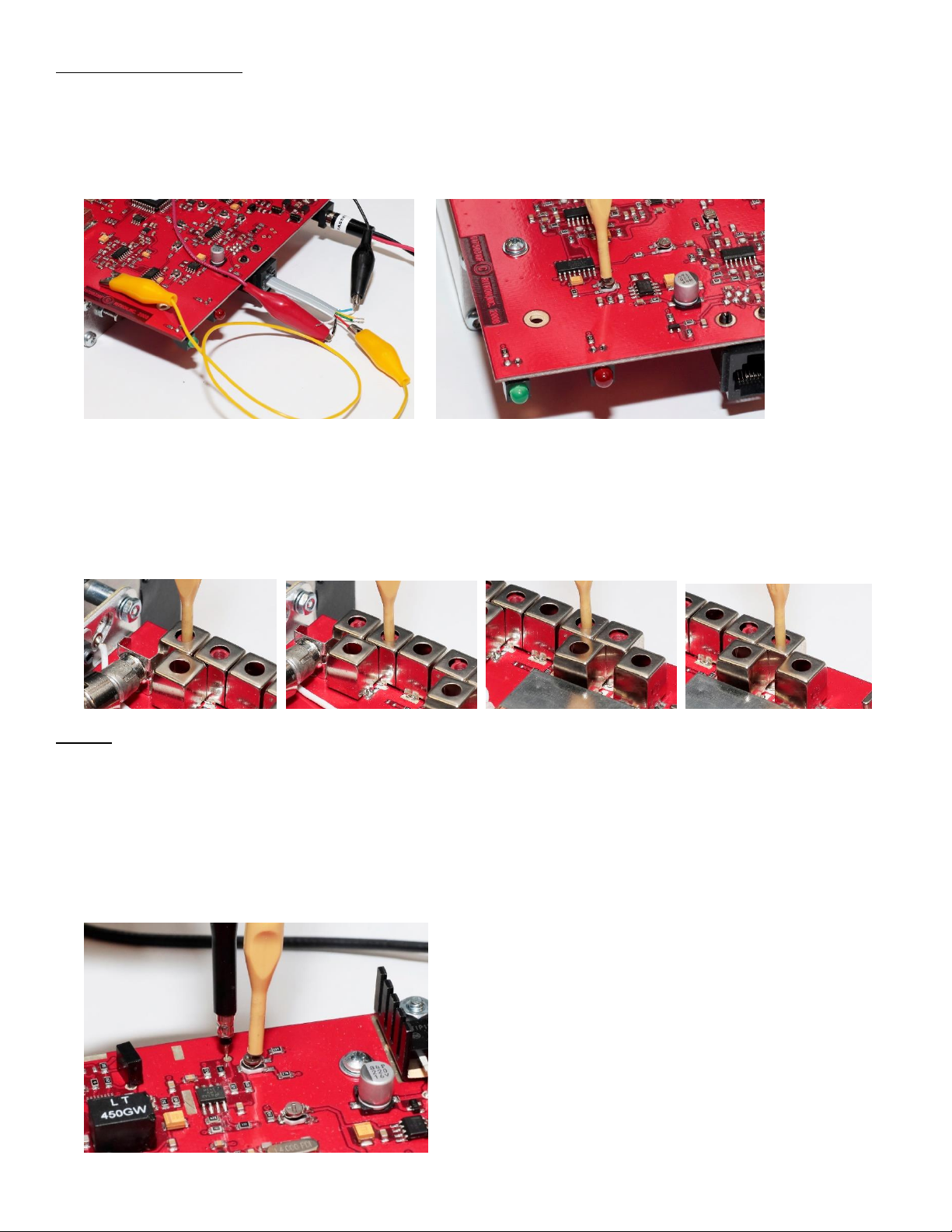
2. Alignment of the Repeater requires connection to the pins on the front panel modular jack. The attached photos will
show the use of a matching modular plug and cable with breakout wires.
3. The frequency deviation numbers shown are for narrow (12.5 kHz channel spacing) operation. Double the values for
wide (25 kHz channel spacing) operation. The RLR-460 does not support both narrow and wide bandwidth operation
in the same model. Separate models exist for each; the RLR-460 for narrow, the RLR-460-W for wide.
4. A communications service monitor capable of duplex operation is required to set R328 (REPEAT AUDIO LEVEL).
Other alignment steps can use individual pieces of equipment (RF signal generator, RF wattmeter, etc.), although
communications service monitors tend to include all the functions necessary to align this product.
5. Ensure that the Repeater is properly programmed for the correct transmit and receive frequencies and the correct
QC/DQC tones/codes. Even if a transmit tone is not to be used (unusual), one should program one anyway to get the
transmit tone deviation properly set (it can then be programmed off). This parameter is, however, set at the factory.
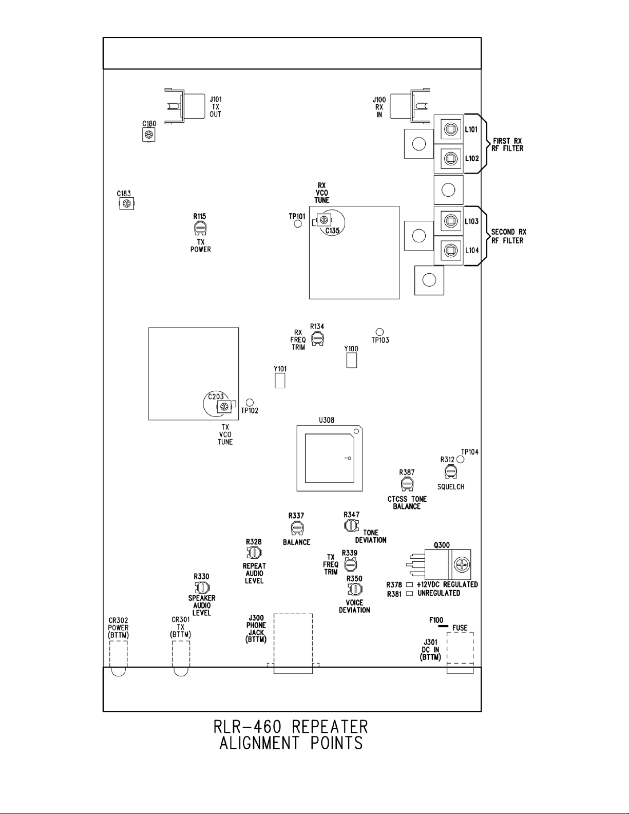
6. Refer to the RLR-460 ALIGNMENT POINTS diagram at the end of these instructions and the accompanying photos
for the location of alignment points and adjustments.
RX High Pass
Tuning Posts
TX Low Pass
Tuning Posts

TRANSMITTER
1. If the Duplexer required re-tuning, reconnect the RX and TX Phono connections to the RX and TX RF Input
connectors on the Radio Board Assembly.
2. Connect the Repeater Antenna Port to the Full Duplex Input/Output of the Service Monitor. Provisions should be
made to couple the RF output signal to a demodulator, a frequency counter, and an RF wattmeter. The demodulated
output must be viewable on an oscilloscope.
3. Set the Service Monitor to receive the Transmit Frequency of the Repeater, and to generate the Receive Frequency
of the Repeater.
4. Connect +13.8VDC to the DC Input of the Repeater. For the DC Power Jack, the center connection is positive(+) and
the outer sleeve is negative(-).
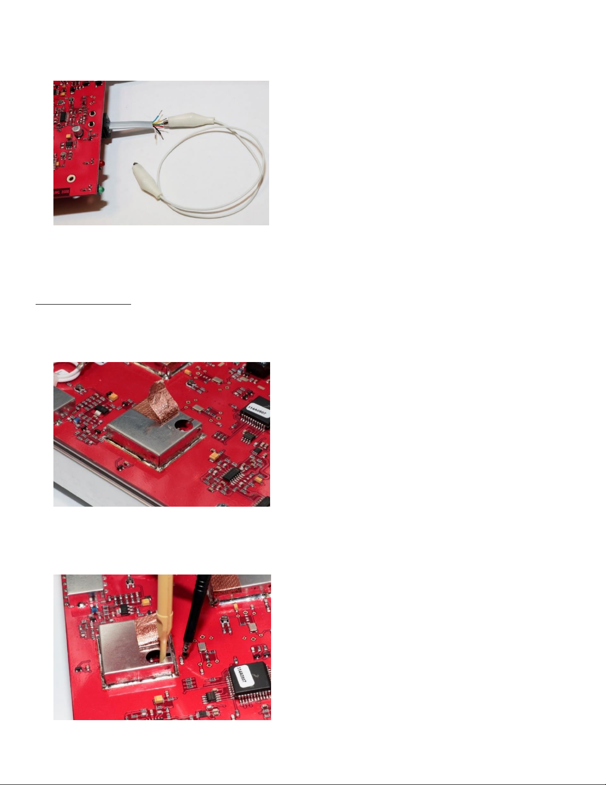
5. Plug in an RJ-11 Plug with 6-Wire Cable. The transmitter will be keyed by taking pin 3 of the modular jack (PTT/MIC)
to ground. Connect wire as shown. Touch the unconnected end of the wire to any available ground to key the
repeater. Note that pin 1 of the modular jack is the Ground pin.
6. Ensure that the signal generator RF output level of the service monitor is set to a very low level (less than -122dBm or
turned OFF) to prevent the receive squelch from unmuting. This will prevent the transmitter from keying due to
receiving a valid carrier. Having a receive QC/DQC tone/code programmed will help greatly in preventing nuisance
keying.
Transmit VCO Tuning
1. Remove the Copper Tape covering the TX VCO Adjustment hole. Connect a high impedance oscilloscope probe
(10X) to an oscilloscope set for 1 V/div, DC coupled. The sweep speed is not important since we will be looking at a
DC level.
2. Connect the ground lead of the probe to the PCB ground. The mounting legs of the transmitter output connector J101
can be used. Key the transmitter, touch the probe tip to TP102 and note the voltage on the oscilloscope. This point is
very sensitive and the synthesizer may go out of lock (red LED blinking). Even if out of lock (green LED flashing), the
voltage can still be adjusted.
3. Using an insulated tuning tool, adjust C203 inside the VCO/synthesizer shield (TX VCO TUNE) for 2.5 +/-0.25 volts at
TP102. The red front panel LED should be illuminated continuously (not blinking) after the probe is removed. Unkey
the transmitter. Replace the foil over the tuning hole.
Transmitter Output Power
1. Key the transmitter and note the output power. Adjust C180 and C183 for maximum output power. If the output
power is too low, adjust R115 (TX POWER) clockwise and readjust C180 and C183. Adjust R115, C180, and C183
until the desired output power is reached. For 2 watts, R115 would typically remain at mid-rotation.
2. Unkey the transmitter.
Transmitter Frequency Trim
1. Key the transmitter and note the frequency of the RF output signal. Adjust
R339 (TX FREQ TRIM) for the correct transmit frequency +/- 100 Hz.
2. Unkey the transmitter.
Modulation Balance and Deviation
1. An audio generator should be connected to the AUDIO IN (pin 2) and Ground (pin 1) of the modular jack. The audio
frequency should be 500 Hz and the level should be 10 mVrms or lower.
2. Set R347 (TONE DEVIATION) to the full counterclockwise position to prevent any signaling tone from being
transmitted.
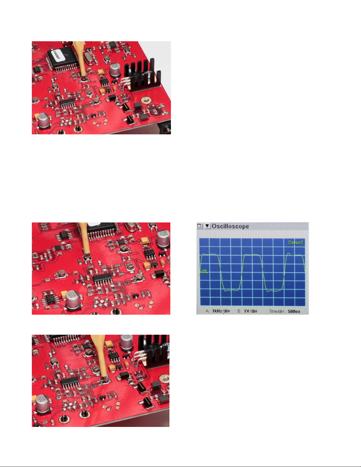
3. The RF output should be routed to an FM demodulator and the demodulated output made visible on an oscilloscope.
The filtering on the demodulator should be 15 kHz or higher on the lowpass filter and below 50 Hz on the highpass
filter. It is important that NO or MINIMUM highpass filtering be in place in the demodulation path.
4. While observing the oscilloscope, key the transmitter. Increase the audio generator level until the 500 Hz sinewave
becomes visible on the oscilloscope. Continue increasing the generator level until a significant amount of clipping on
the top and bottom of the sinewave is evident (typically 250 mVrms).
5. Carefully adjust R337 (BALANCE) so that the clipped portion of the observed waveform is flat i.e. not tilted up or
down.
6. Adjust R350 (VOICE DEVIATION) for +/- 2.35 kHz deviation.
7. Unkey the transmitter.
Tone Deviation
1. Key the transmitter and adjust R347 (TONE DEVIATION) for the desired tone/code deviation, typically 400 Hz.
2. Unkey the transmitter.
RECEIVER
1. Apply power to the Repeater. The green front panel LED should be illuminated, but may be blinking.
2. Connect the MON input (modular jack pin 4) to ground (modular jack pin 1). This will override the tone squelch
operation and also inhibit the transmitter.
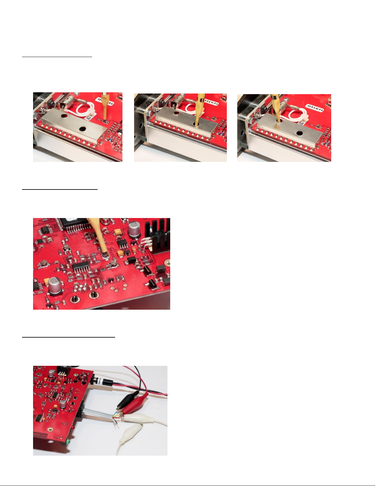
Receive VCO Tuning
1. Connect a high impedance oscilloscope probe to an oscilloscope set for 1 V/div, DC coupled. The sweep speed is
not important.

2. Remove the Copper Tape covering the RX VCO Tuning hole. Connect the ground lead of the probe to the PCB
ground. The mounting legs of the receiver input connector J100 can be used. Touch the probe tip to TP101 and note
the voltage on the oscilloscope. This point is very sensitive and the synthesizer may go out of lock. Even if out of
lock (green LED flashing), the voltage can still be adjusted.
3. Using an insulated tuning tool, adjust C135 inside the VCO/synthesizer (RX VCO TUNE) shield for 2.5 +/-0.25 volts at
TP101. The green front panel LED should be illuminated continuously (not blinking) when the probe is removed.
Replace the Copper Tape over the tuning hole.
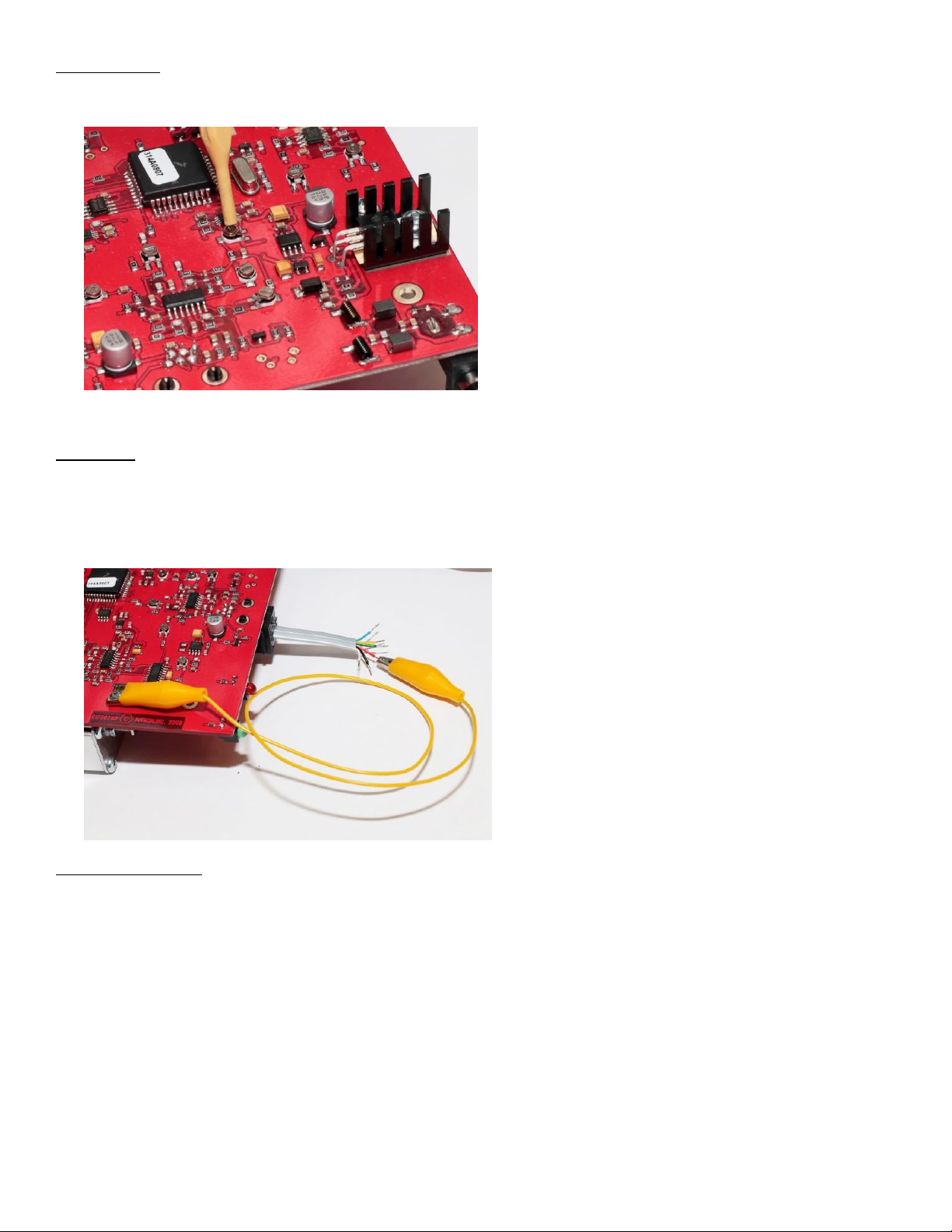
Local Oscillator Trim
1. Connect a test probe from a frequency counter or frequency measuring device to test point TP103. The receiver 1st
local oscillator signal at approximately –12dBm is present at this point. The correct frequency at this point is the
receive frequency minus the 1st IF frequency of 43.65 MHz (fLO = fRX - 43.65).
2. Using a tuning tool, adjust R134 (RX FREQ TRIM) for the correct frequency +/-100 Hz.
Receiver Front-End Tuning
Note: Connect the MON input (modular jack pin 4) to ground (modular jack pin 1). This will keep the Squelch function
from muting the receiver.
1. Connect a SINAD meter to the AUDIO OUT output (pin 5) to Ground (pin 1). Set R330 (SPEAKER AUDIO LEVEL) to
mid rotation.
2. Set the generated output of the Service Monitor to the desired receive frequency modulated with a 1 kHz tone at 1.5
kHz deviation. The RF level should be set to 7uV (–90dBm).
3. If the SINAD meter reads greater than 12 dB, reduce the RF signal generator output level until 12 dB SINAD is
reached. Adjust L101 through L104 for best SINAD while reducing the RF signal generator output level to keep the
SINAD near 12dB. The RF output level for 12 dB SINAD should be 0.25uV (-119dBm) or less. Note that all of the
inductors have a very broad tuning characteristic, except L103. Adjust the inductors in the middle of this broad range.
Squelch
1. Set the RF signal generator output level to produce a SINAD reading where the squelch is desired to unmute, typically
12-14dB. Remove the wire jumper from the Monitor Input (pin 4) of the RJ11 connector.
2. Rotate R312 (SQUELCH) to the maximum counterclockwise point. Connect an oscilloscope probe to TP104. The
voltage at TP104 should be 5 VDC. Adjust R312 clockwise until the TP104 voltage drops to zero. Then, slowly adjust
R312 counterclockwise to the point where the TP104 voltage again goes to 5 volts. Conversely, if ‘override tone’ is
set for squelch mode in the programmer menu, one can listen for the presence or absence of audio at the audio
output to determine the squelch point.

Audio Output Level
1. Increase the RF signal generator output level to 7uV (-90dBm) and add a 100Hz CTCSS Tone at +/- 450Hz deviation.
The SINAD reading should be close to 20 dB or so. Connect an oscilloscope to the AUDIO OUT (pin 5) on the
modular jack. The SINAD meter is already connected to this point.
2. Adjust R330 (SPEAKER AUDIO LEVEL) for the desired output level of the 1kHz tone.
3. Connect the oscilloscope to pin 7 of U300 and adjust R387 for a symmetrical 100Hz square wave.
Repeat Audio Level
1. For this adjustment, the service monitor must be able to generate an RF signal and simultaneously demodulate an
incoming RF signal.
2. Set the RF signal generator for the correct receive frequency with 1.5 kHz deviation of a 1 kHz tone and modulated
with the correct tone/code, if used. The RF output level should be set for 7uV (-90dBm) The demodulator should be
set to display deviation.

3. The transmitter should automatically key (red LED illuminated). Adjust R328 (REPEAT AUDIO LEVEL) for +/- 1.8
kHz deviation.
Reduce the RF signal generator level to minimum to unkey the transmitter.
RE-ASSEMBLY
1. Disconnect all equipment from the repeater radio assembly.
2. To re-assemble the repeater, slide the radio assembly into the open end of the repeater enclosure.
3. Be sure that the connectors and LEDs line up with the openings at the closed end of the repeater enclosure. Insert
and tighten the six T-10 torx screws into the end plate with the antenna connector as indicated by the white arrows.
4. The re-assembly is complete.

FINAL TEST –DESENSE
1. Connect the Full Duplex Input/Output of the Service Monitor to the Repeater Antenna Connection.
2. Apply power to the Repeater.
2. Set the Generated RF Signal of the Service Monitor to the Receive Frequency of the Repeater. Set the RF level low
enough as to not cause the Repeater to transmit.
3. Set the Received Signal of the Service Monitor to the Transmit Frequency of the Repeater.
4. Plug in the RJ11 Test Jack and connect a wire from Pin 4(Monitor) to Pin 1(Ground) of the RJ11 Test Jack. This will
keep the Repeater from transmitting.
5. Connect a SINAD Meter to Pin 5(Audio Out) to Pin 1(Ground) of the RJ11 Test Jack.
6. Increase the generated RF Signal from the Service Monitor until 12dB SINAD is measured on the SINAD Meter.
7. Remove the wire from Pin 4 of the RJ11 Test Jack. The Repeater should automatically transmit.
8. The SINAD measurement should remain at 12dB –11.5dB SINAD. If the SINAD measurement drops below 11.5dB
SINAD, re-tune the RX and TX sections of the Duplexer for -65db notch measurement minimum.
Other manuals for Liberty RLR-460
1
This manual suits for next models
1
Other Ritron Repeater manuals


