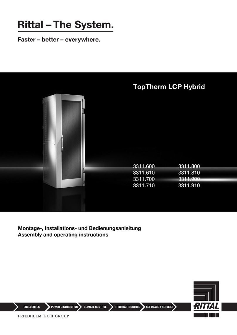
Rittal TopTherm LCP Rack CW User manual

TopTherm LCP Rack CW
TopTherm LCP Inline CW
TopTherm LCP Inline flush CW
3311.138/238/268
3311.538/568
3311.148/548
Montage-, Installations- und Bedienungsanleitung
Assembly and operating instructions
Notice d'emploi, d'installation et de montage
Montage- en bedieningshandleiding

Foreword
EN
2Rittal Liquid Cooling Package
Foreword
Dear Customer!
Thank you for choosing a Rittal Liquid Cooling
Package (referred to hereafter also as "LCP").
This documentation applies to the following three units
in the LCP series:
–LCPRackCW
– LCP Inline CW
– LCP Inline flush CW
Those sections where information only applies to one
of the three units are labelled accordingly in the doc-
umentation.
Please take the time to read this documentation care-
fully and pay particular attention to the safety instruc-
tions in the text and to section 2 "Safety instructions".
This is the prerequisite for:
– secure assembly of the Liquid Cooling Package
– safe handling and
– the most trouble-free operation possible.
Please keep the complete documentation readily
available so that it is always on hand when needed.
We wish you every success!
Your,
Rittal GmbH & Co. KG
Rittal Corporation
1 Rittal Place
Urbana, Ohio 43078 USA
Tel.: 800-477-4000
Fax: 800-477-4003
E-mail: rittal@rittal-corp.com
www.rittal-corp.com
We are always happy to answer any technical ques-
tions regarding our entire range of products.

Rittal Liquid Cooling Package 3
Contents
EN
Contents
1 Notes on documentation ................. 5
1.1 CE labelling .................................................. 5
1.2 Storing the documents ................................. 5
1.3 Symbols in these operating instructions ...... 5
1.4 Other applicable documents ....................... 5
1.5 Normative instructions ................................. 5
1.5.1 Legal information concerning the operating
instructions .......................................................... 5
1.5.2 Copyright ............................................................. 5
1.5.3 Revision ............................................................... 5
2 Safety instructions ........................... 6
2.1 Important safety instructions: ....................... 6
2.2 Service and technical staff .......................... 7
2.3 RoHS compliance ........................................ 7
3 Device description .......................... 8
3.1 General functional description ..................... 8
3.2 Air routing .................................................. 11
3.2.1 General .............................................................. 11
3.2.2 LCP Rack .......................................................... 11
3.2.3 LCP Inline and LCP Inline flush ......................... 12
3.3 Equipment assembly ................................. 13
3.3.1 Schematic design ............................................. 13
3.3.2 Unit components ............................................... 13
3.3.3 Air/water heat exchanger .................................. 15
3.3.4 Fan module ....................................................... 15
3.3.5 Water module with cold water connection ........ 16
3.4 Proper and improper usage ...................... 16
3.5 Supply scope of a Liquid Cooling
Package ..................................................... 17
3.6 Unit-specific instructions ........................... 17
3.6.1 Creation of redundancy in the LCP Rack .......... 17
3.6.2 Dewpoint control ............................................... 19
4 Transportation and handling ......... 20
4.1 Transportation ............................................ 20
4.2 Unpacking ................................................. 20
5 Assembly and siting ..................... 21
5.1 General ...................................................... 21
5.1.1 Installation site requirements ............................ 21
5.1.2 Prepare the room for installation of the LCP Inline
and LCP Inline flush .......................................... 21
5.1.3 Installation regulations for the LCP Inline and
LCP Inline flush ................................................. 21
5.2 Assembly procedure ................................. 22
5.2.1 General .............................................................. 22
5.2.2 Dismantle the side panels ................................. 22
5.2.3 Seal the server enclosure .................................. 22
5.2.4 Dismantle the server enclosure door ................ 24
5.2.5 Fit the rear adaptor on the LCP Inline ............... 24
5.2.6 Fit the trim panels if siting without a rear
adaptor .............................................................. 25
5.2.7 Installation and baying of the Liquid Cooling
Package ............................................................ 25
5.2.8 Mounting the side panel .................................... 26
5.3 Fan installation .......................................... 26
5.3.1 Removing a fan module .................................... 27
5.3.2 Installing a fan module ...................................... 29
5.4 Install the optional display (3311.030) ...... 30
6 Installation ..................................... 31
6.1 Connecting the Liquid Cooling Package .. 31
6.1.1 Electrical connection ......................................... 31
6.1.2 Cooling water connection ................................. 32
6.1.3 Connecting the condensate discharge ............. 34
6.1.4 Bleeding the air from the heat exchanger ......... 35
6.2 Cooling operation and control
characteristics .......................................... 35
7 Commissioning checklist ............... 36
8 Configuration ................................. 39
8.1 General ..................................................... 39
8.2 HTTP connection ...................................... 39
8.2.1 Making the connection ...................................... 39
8.2.2 Changing the network settings ......................... 39
8.2.3 Changing the measurement units ..................... 40
8.2.4 LCP configuration .............................................. 40
8.2.5 Settings ............................................................. 45
9 Operation ...................................... 46
9.1 Description of operating and display
components .............................................. 46
9.1.1 Control unit hardware for the Liquid Cooling
Package ............................................................ 46
9.2 Description of operation ........................... 46
9.2.1 General .............................................................. 46
9.2.2 Acknowledging messages ................................ 47
9.2.3 Operation in stand-alone mode ........................ 48
9.2.4 Automatic door opening, LCP Rack .................. 51
9.3 Extended options by connecting the Liquid
Cooling Package to a network .................. 52
9.4 General operation ..................................... 52
9.4.1 Layout of screen pages .................................... 52
9.4.2 Selection tree in left-hand section ..................... 53
9.4.3 Index tabs in the right-hand section ................. 53
9.4.4 Message display ............................................... 53
9.4.5 Other displays ................................................... 54
9.4.6 Changing parameter values .............................. 55
9.4.7 Logging off and changing the password .......... 56
9.4.8 Reorganising the connected components ........ 56
9.5 Observation index tab .............................. 57
9.5.1 Device ............................................................... 58
9.5.2 Air ...................................................................... 58
9.5.3 Water ................................................................. 60
9.5.4 Config ................................................................ 62
9.6 Configuration index tab ............................ 62
9.7 Tasks ......................................................... 63
10 Troubleshooting ............................ 64
11 Inspection and maintenance ......... 66
12 Storage and disposal .................... 67

Contents
EN
4Rittal Liquid Cooling Package
13 Technical specifications ................ 68
13.1 30 kW versions .......................................... 68
13.1.1 LCP Rack and LCP Inline .................................. 68
13.1.2 LCP Inline flush .................................................. 69
13.2 60 kW versions .......................................... 70
13.3 External fuse/breaker sizes (US) .............. 71
14 Spare parts .................................... 72
15 Accessories ................................... 73
16 Further technical information ......... 74
16.1 Hydrological information ........................... 74
16.2 Characteristic curves ................................ 75
16.2.1 Cooling output ................................................... 75
16.2.2 Pressure loss ..................................................... 78
16.3 Overview drawings ................................... 80
16.4 Circuit diagram ......................................... 83
16.4.1 Control unit hardware for the fan modules
(RLCP fan) ......................................................... 84
16.4.2 Control unit hardware for the water module
(RLCP water) ...................................................... 84
16.4.3 Hardware for startup current limitation .............. 85
16.5 Water circulation diagram ......................... 85
17 Preparation and maintenance of the
cooling medium ............................. 86
18 Frequently Asked Questions
(FAQ) ............................................. 87
19 Glossary ........................................ 91
20 Customer service addresses ........ 92

Rittal Liquid Cooling Package 5
1 Notes on documentation
EN
1 Notes on documentation
1.1 CE labelling
Rittal GmbH & Co. KG hereby confirms that the cool-
ing units in the Liquid Cooling Package series are
compliant with the EC EMC Directive 2004/108/EC. A
corresponding declaration of conformity has been is-
sued and enclosed with the documentation package
supplied with the unit.
The cooling unit bears the following mark.
1.2 Storing the documents
The assembly and operating instructions as well as all
applicable documents are integral components of the
product. They must be handed out to those persons
who are engaged with the unit and must always be
available and on hand for operating and maintenance
personnel.
1.3 Symbols in these operating instructions
The following symbols are found in this documenta-
tion:
This symbol indicates an "Action Point" and shows
that you should carry out an operation/procedure.
1.4 Other applicable documents
In conjunction with these assembly and operating in-
structions, the superordinate system documentation
(if available) also applies.
Rittal GmbH & Co. KG is not responsible for any dam-
age which may result from failure to comply with these
assembly and operating instructions. The same ap-
plies to failure to comply with the valid documentation
for accessories used.
1.5 Normative instructions
1.5.1 Legal information concerning the operating
instructions
We reserve the right to make changes in content.
Rittal GmbH & Co. KG will not be held liable for any
mistakes in this documentation. Liability for indirect
damages which occur through the delivery or use of
this documentation is excluded to the extent allowable
by law.
1.5.2 Copyright
The distribution and duplication of this document and
the disclosure and use of its contents are prohibited
unless expressly authorised.
Offenders will be liable for damages. All rights created
by a patent grant or registration of a utility model or
design are reserved.
1.5.3 Revision
Rev. 0A of 12/16/2013
Danger!
Hazardous situation which may lead to
death or serious injury if the instructions
are not followed.
Warning!
Hazardous situation which may lead to
death or serious injury if the instructions
are not followed.
Caution!
Hazardous situation which may lead to
(minor) injuries if the instructions are not
followed.
Note:
Information concerning individual proce-
dures, explanations, or tips for simplified ap-
proaches. Also indicates situations which
may result in material damage.

2 Safety instructions
EN
6Rittal Liquid Cooling Package
2 Safety instructions
The Liquid Cooling Packages produced by Rittal
GmbH & Co. KG are developed and produced with
due regard to all safety precautions. Nevertheless, the
unit still causes a number of unavoidable dangers and
risks. The safety instructions provide you with an over-
view of these dangers and the necessary safety pre-
cautions.
In the interest of your safety and the safety of others,
please read these safety instructions carefully before
assembly and commissioning of the Liquid Cooling
Package.
Follow the user information found in these instructions
and on the unit carefully.
2.1 Important safety instructions:
As a general requirement, please observe the follow-
ing five safety rules to DIN VDE 0105 when working in
and on the Liquid Cooling Package, in order to avoid
accidents:
1. Switch off!
Switch off the Liquid Cooling Package at the mas-
ter switch.
2. Prevent reactivation!
3. Ensure that all poles are de-energised!
4. Earth and short-circuit!
5. Cover or shield adjacent, live parts!
Danger! Electric shock!
Contact with live electrical parts may be
lethal.
Before switching on, ensure that it is not
possible to come into contact with live
electrical parts.
The unit has a high discharge current. For
this reason, it is essential to make a
10 mm earth connection before connect-
ing to the supply circuit (see section 16.4
"Circuit diagram").
Danger! Injury caused by fan impellors!
Keep persons and objects away from the
fan impellors! Do not remove covers until
the power supply is disconnected and im-
pellors are not moving! Always use me-
chanical protection when working! Shut
down the respective fan during mainte-
nance work, if possible! Tie long hair
back! Do not wear loose clothing!
Fans start up automatically following
power disruptions!
Danger! Cut wounds, especially through
sharp edges of the fan and heat exchang-
er modules!
Put on protective gloves before beginning
assembly or cleaning work!
Danger! Injury due to falling loads!
Do not stand under suspended loads
when transporting the unit with a hoist
trolley, a forklift, or a crane.
Caution! Risk of malfunction or damage!
Do not modify the unit! Use only original
spare parts!
Caution! Risk of malfunction or damage!
Proper and flawless unit operation can
only be ensured when it is operated under
the intended ambient conditions. As far
as possible, be sure that the ambient con-
ditions for which the unit is designed are
complied with, e.g. temperature, humidity,
air purity.
Caution! Risk of malfunction or damage!
All media necessary for the control sys-
tem, e.g. cooling water, must be available
during the entire operating time.
Caution! Risk of malfunction or damage!
It is vital that the manufacturer's consent
is obtained before adding anti-freeze!
Caution! Risk of malfunction or damage!
During storage and transportation below
freezing point, the water cycle should be
drained completely using compressed
air!
Caution! Risk of malfunction or damage!
Only set the temperature control setpoint
as low as is strictly necessary, since the
danger of condensation through under-
cutting the dew point increases with a fall-
ing water inlet temperature!
Ensure that the enclosure is sealed on all
sides, particularly at the cable entry (con-
densation)!

Rittal Liquid Cooling Package 7
2 Safety instructions
EN
2.2 Service and technical staff
The installation, commissioning, maintenance and re-
pair of this unit may only be carried out by qualified
mechanical and electro-technical trained personnel.
Only properly instructed personnel may perform serv-
ice on a unit while in operation.
2.3 RoHS compliance
The Liquid Cooling Package fulfils the requirements of
EU directive 2002/95/EC on the Restriction of Use of
Certain Hazardous Substances in Electrical and Elec-
tronic Equipment (RoHS) of 13 February, 2003.
Note:
Corresponding information concerning the
RoHS directive is provided by our firm on the
Internet at www.rittal.de/RoHS.

3 Device description
EN
8Rittal Liquid Cooling Package
3 Device description
3.1 General functional description
The Liquid Cooling Package is essentially an air/water
heat exchanger that is used to dissipate high heat
losses from server enclosures or for the effective cool-
ing of devices built into a server enclosure.
The air routing in the Liquid Cooling Package sup-
ports the "front to back" cooling principle of the devic-
es built into the server enclosure. The hot air expelled
by the devices in the server enclosure is drawn in by
the fans at the rear directly from the server enclosure
(LCP Rack) or from the hot aisle (LCP Inline and LCP
Inline flush) and thus routed through the heat ex-
changer module.
In the heat exchanger module, the heated air is direct-
ed through an air/water heat exchanger, and its ther-
mal energy (heat losses from the server) is transferred
to a cold water system. As a result, the air is cooled to
a freely selectable temperature within the authorised
parameters and then routed directly in front of the
482.6 mm (19") level in the server enclosure (LCP
Rack) or into the cold aisle (LCP Inline and LCP Inline
flush).
In its delivered state, the LCP Inline expels the cold air
on both sides. By fitting a side panel or partition, this
can be restricted to one side only.
Fig. 1: Air routing on the LCP Rack – top view
Key
1 Air inlet
2 Heat exchanger
3Airoutlet
4 Fan module
5 2nd air inlet
6 2nd air outlet
Fig. 2: Air routing on the LCP Rack – top view
Key
1 Air inlet
2 Heat exchanger
3Airoutlet
4 Fan module
Fig. 3: Air routing on the LCP Inline flush – top view
Key
1 Air inlet
2 Heat exchanger
3 Fan module
4Airoutlet
2
15
63
4
2
1
33
4
2
1
3
4

Rittal Liquid Cooling Package 9
3 Device description
EN
The temperature of the cold air intake is controlled via
constant comparison of the actual temperature with
the setpoint temperature set on the Liquid Cooling
Package control unit (default is +20 °C).
If the server-in temperature exceeds the setpoint tem-
perature, the control valve in the cooling water system
opens (linear opening from 0 – 100%), and the heat
exchanger is supplied with cold water.
The temperature differential between the setpoint and
the warm air that is drawn is used to determine and set
the fan speed. The control unit attempts to keep the air
temperature constant in front of the 482.6 mm (19")
level (LCP Rack) or in the cold aisle (LCP Inline and
Inline flush) by activating the control valve.
Any condensate incurred is collected in the conden-
sate collecting tray built into the water module of the
Liquid Cooling Package, and from there is routed out-
side via a condensate discharge hose.
Note:
The water inlet temperature must always be
selected (controlled) to be above the dew
point for the existing ambient temperature
and humidity in the data centre. The dew
point can be found in the Mollier h-x diagram
(fig. 4).
Furthermore, we advise compliance with the
ASHRAE standard "ASHRAE TC 9.9, 2011
Thermal Guidelines for Data Processing En-
vironments".

3 Device description
EN
10 Rittal Liquid Cooling Package
Fig. 4: Mollier h-x diagram for humid air
1.25 kg/m3
1.20 kg/m3
1.15 kg/m3
1.10 kg/m3
1.05 kg/m3
0 kJ/kg
20 kJ/kg
40 kJ/kg
60 kJ/kg
Enthalpy
100%
50%
90%
80%
70%
60%
40%
30%20%15%10%5%
Rel. Humidity
0 g/kg
2 g/kg
4 g/kg
6 g/kg
8 g/kg
10 g/kg
12 g/kg
14 g/kg
16 g/kg
18 g/kg
20 g/kg
Water
-15 º
-10 º
-5 º
0 º
5 º
10 º
15 º
20 º
25 º
30 º
35 º
40 º
Temperature
Mollier h-x diagram for humid air – pressure 0.950 bar (537.000 m / 10.000 ºC / 80.000%rF)

Rittal Liquid Cooling Package 11
3 Device description
EN
3.2 Air routing
3.2.1 General
In order to achieve sufficient cooling in the server en-
closure, it is important to ensure that the cooling air
passes through the interior of the built-in units and is
unable to flow past at the sides.
Targeted air routing in the server enclosure has a ma-
jor effect on the heat loss to be dissipated.
In order to ensure targeted air routing in the system,
the server enclosure should be divided vertically into
warm air and cold air sections. The division is accom-
plished in the front section of the server assembly to
the left and right of the 482.6 mm (19") level using
foam strips or air baffle plates which, depending on
the enclosure width and the number of server enclo-
sures to be cooled, can be ordered as an accessory
(see section 15 "Accessories").
If devices which require sideways air throughput are
built into the server enclosure (e.g. switches, router,
etc.), these may be cooled through targeted place-
ment of the foam strips or air baffle plates.
3.2.2 LCP Rack
The LCP Rack may be bayed on the right or left of a
server enclosure, according to preference.
Fig. 5: LCP Rack on a server enclosure
The LCP Rack may also be bayed between two server
enclosures.
Fig. 6: LCP Rack on two server enclosures
Together with the bayed server enclosure, the LCP
Rack forms an airtight cooling system with horizontal
air routing. It places no additional demands on the
room's climate control system.
Note:
The 482.6 mm (19") level must likewise be
completely sealed. This is already the case
in a fully equipped server enclosure. If the
server enclosure is partially equipped, the
open height units (U) of the 482.6 mm (19")
level must be sealed with blanking plates,
which are available from Rittal Accessories
(see section 15 "Accessories").
As more devices are installed in the server
enclosure, it becomes even more important
to follow this specification.

3 Device description
EN
12 Rittal Liquid Cooling Package
Fig. 7: Air routing with a bayed server enclosure – top view
Key
1LCPRack
2 Server enclosure
Fig. 8: Air routing with two bayed server enclosures – top
view
Key
1 Server enclosure
2LCPRack
The system consisting of the LCP Rack and the server
enclosure should be sealed as effectively as possible
in order to prevent the loss of cooling air. To accom-
plish this, the enclosure is equipped with side panels,
roof and gland plates. Any existing cable entries
should be sealed e.g. using suitable brush strips.
Whilst the system is in operation, both the front and the
rear doors should be kept completely shut.
3.2.3 LCP Inline and LCP Inline flush
Targeted air routing by hot air extraction from the hot
aisle and cold air blown into the cold aisle has a fun-
damental effect on the amount of heat to be dissipat-
ed.
In order to achieve sufficient cooling in the server en-
closure, it is important to ensure that the cooling air
passes through the interior of the built-in units and is
unable to flow past at the sides.
Fig. 9: Air routing with bayed server enclosures – top view
Key
1LCPInline
2 Server enclosure
3 LCP Inline flush
For this purpose, the system consisting of LCP Inline
or LCP Inline flush, server enclosure and cold aisle
containment should be sealed as effectively as possi-
ble in order to avoid a decrease in cooling capacity
due to mixing of cold and hot air. This is achieved by
sealing the cold aisle with doors at the beginning and
end of the rack rows, and sealed against the ceiling
with roof elements. Existing cable entry glands are ad-
ditionally sealed e.g. with suitable brush strips.
21
211
Note:
However, the system does not need to be
completely airtight, thanks to the high, coor-
dinated air throughputs of the server and
LCP fans.
21
3222

Rittal Liquid Cooling Package 13
3 Device description
EN
3.3 Equipment assembly
3.3.1 Schematic design
The schematic design is illustrated below:
Fig. 10: Schematic design of a Liquid Cooling Package –
right-hand side view
Key
1 Fuse box with master switch (see fig. 11, item 6)
2 Water PCB
3 Fan PCB
4 Startup current limitation
5 Air/water heat exchanger
6 Water module
7 Fan 6 (not with LCP Inline flush)
8 Fan 5 (not with LCP Inline flush)
9 Fan 4
10 Fan 3
11 Fan 2
12 Fan 1
13 Control unit CMC III PU (see fig. 11, item 5)
The Liquid Cooling Package consists of a fuse box, a
superordinate control unit (CMC III PU), a water mod-
ule, a heat exchanger, and the fan modules. In its sup-
plied state, the following fan modules are built into the
devices:
Tab. 1: No. of fan modules in supplied state
The fan modules and the water module contain their
own electronic controls (1 x RLCP fan and 1 x RLCP
water), which are connected to the CMC III PU via a
CAN bus. The fan modules are switched on sequen-
tially from one to six (or one to four with
LCP Inline flush) via a startup current limitation once
connected to the mains voltage.
3.3.2 Unit components
Fig. 11: Liquid Cooling Package front – open front door
(60 kW variant)
Key
1 LCP door
2 Optional display with touch function (rear)
3 Fans (in this instance, fully equipped with 6 fans)
4 Rack
5 Control unit CMC III PU (see fig. 10, item 13)
6 Fuse box with master switch (see fig. 10, item 1)
Device/cooling output 30 kW 55 kW
LCP Rack 1 module 4 modules
LCP Inline 1 module 4 modules
LCP Inline flush 2 modules –
11
9
7
6
12
10
8
13
5
1234
1
2
6
5
3
3
3
3
4
3
3

3 Device description
EN
14 Rittal Liquid Cooling Package
Fig. 12: LCP Inline flush front – open front door
Key
1 LCP door
2 Installation location for optional display with touch
function
3 Fans (in this instance, fully equipped with 4 fans)
4 Rack
5 Control unit CMC III PU (see fig. 10, item 13)
6 Fuse box with master switch (see fig. 10, item 1)
The fuse box is comprised of the following compo-
nents:
– Thermally activated master switch
– 3 thermally activated switches for fan pairs 1/2, 3/4
and 5/6
– AC/DC power pack for CMC III PU supply
– EMC line filter
Fig. 13: Fuse box with master switch
Key
1 Thermally activated switch, fan pair 1/2
2 Thermally activated switch, fan pair 3/4
3 Thermally activated switch, fan pair 5/6
4 Thermally activated master switch
Fig. 14: LCP Rack rear – rear door open
Key
1 LCP rear door
2 Condensate collecting tray and condensate dis-
charge
3 Water connection, return
4 Water connection, inlet
5 Air/water heat exchanger
6 Vent valve
7 Mains connection, network connection and connec-
tion of optional condensate pump
1
2
6
5
3
3
4
3
3
1234
1
7
5
2
6
3
4

Rittal Liquid Cooling Package 15
3 Device description
EN
The Liquid Cooling Package consists of a solid weld-
ed frame in which the heat exchanger, fan modules,
and the water module are installed.
One wide and one narrow wall plate are mounted on
both the left and right sides.
The wall plates have been punched with air outlet
openings along their entire height in the front section
to ensure cold air supply to the server (LCP Rack) or
to the cold aisle (LCP Inline).
In the LCP Rack, the wall plates in the rear section
have been punched with air inlet openings along their
entire height and width to ensure the dissipation of
warm air from the server.
Seven shelves (or in the case of the LCP Inline flush,
five shelves) are positioned between these wall plates
that divide the front of the Liquid Cooling Package into
several compartments of differing heights. The top
shelf supports the fuse box, the control unit
(CMC III PU), the fan and water PCB, and the startup
current limitation. The compartments for the fans are
below this. All components of the cooling water supply
and condensate management are integrated into the
water module on the floor of the Liquid Cooling
Package.
The front and rear of the Liquid Cooling Package are
each closed with a door with 4-point locking.
In the LCP Rack these doors seal the unit. In the LCP
Inline and LCP Inline flush, the rear door is perforated
to ensure the dissipation of hot air from the hot aisle.
In the LCP Inline flush, the front door is additionally
perforated to ensure the supply of cooling air into the
cold aisle.
The optional display with touch function for operation
in stand-alone mode is located on the front.
3.3.3 Air/water heat exchanger
The air/water heat exchanger is installed in the centre
section of the Liquid Cooling Package between the
two wall plates. In 30 kW units (3311.138/148/238/
538/548), the heat exchanger is covered with a spray
eliminator on the air outlet side that catches any con-
densate and directs it to the condensate collecting
tray at the bottom of the Liquid Cooling Package.
Three temperature sensors are mounted on the rear of
the spray eliminator at the level of the fan modules.
The sensors record the temperature of the cold air in-
take and send it to the control unit.
3.3.4 Fan module
Fig. 15: Fan module in fan tray – LCP Inline and LCP Rack
version
Key
1 Screws
2 Connection cable for display with touch function
3 Connector DC
4 Earth connection
5 Connector AC
6 Fan
7 Handle
Note:
In principle, the rear of the LCP Inline and the
LCP Inline flush looks exactly the same as
the LCP Rack, except that they have a perfo-
rated door.
7
6
1
1
3
2
1
5
1
1
4

3 Device description
EN
16 Rittal Liquid Cooling Package
Fig. 16: Fan module in fan tray – LCP Inline flush version
Key
1 Air baffle plate
2 Connector DC
3 Earth connection
4 Fan
5 Handle
6 Connector AC
7Screws
A fan module is essentially comprised of the fan itself.
All fan modules are controlled by a shared control unit
(RLCP fan) which is mounted in the upper section of
the Liquid Cooling Package. The fans may be operat-
ed with linear control from 0%–100%.
The fan modules are installed on rack-mounted
shelves in the front section of the Liquid Cooling
Package.
The two connection cables for the power supply and
pilot wire are routed out of the underside of the fan. In
the LCP Rack and LCP Inline, the intake end of the fan
module lies against a sealing section mounted on the
left and right of the rack, which forms an effective seal.
In the LCP Inline flush, the fans lie directly against the
rack. This means that in the installed state, the fans
are connected directly to the unit's air/water heat ex-
changer, enabling the air from the air/water heat ex-
changer to be routed directly and without interruption
to the fan module.
It takes about 2 minutes to replace a fan module dur-
ing operation (see section 5.3 "Fan installation").
3.3.5 Water module with cold water connection
A significant component of the water module is the
stainless steel condensate collecting tray, on which a
leak sensor and a condensate discharge are located.
In addition to the leak sensor, the condensate tray is
also equipped with a pressureless condensate dis-
charge. This directs the condensate out of the Liquid
Cooling Package to the rear. The hose must be con-
nected to an external discharge (see section 6.1.3
"Connecting the condensate discharge").
The pipework for the Liquid Cooling Package's cool-
ing water connection (inlet and return) runs above the
condensate collecting tray.
The lines connect the rear-mounted cooling water
connection with the air/water heat exchanger built into
the front of the device. The lines are insulated to avoid
the formation of condensation. A motorised control
valve is located in the cooling water inlet line to control
the cooling water flow.
The control unit of the water module is fitted in the up-
per section, below the power supply to the Liquid
Cooling Package.
The cooling water connection is connected to the
main inlet and return connections by two 1½" external-
ly threaded pipes for flange gaskets. The connection
nozzles are positioned horizontally to the rear.
The cooling water connection to the cold water net-
work can be made by either rigid pipework or flexible
hoses, which are available from the Rittal accessory
range (see section 15 "Accessories").
3.4 Proper and improper usage
The Liquid Cooling Package is used to dissipate high
heat losses and effectively cool devices built into a
server enclosure. The unit is designed solely for sta-
tionary use in sealed rooms.
The unit is state of the art and built according to rec-
ognised safety regulations. Nevertheless, improper
use can present a hazard to life and limb of the user
or third parties, or result in possible damage to the
system and other property.
Consequently, the unit must only be used properly
and in a technically sound condition.
Any malfunctions which impair safety should be recti-
fied immediately. Follow the operating instructions!
Proper use also includes following the operating in-
structions and fulfilling the inspection and mainte-
nance conditions.
Inappropriate use may result in danger. Inappropriate
use may include:
– Use of impermissible tools.
– Improper use.
– Improper rectification of malfunctions.
5
6
4
2
1
3
7
1

Rittal Liquid Cooling Package 17
3 Device description
EN
– Use of replacement parts which are not authorised
by Rittal GmbH & Co. KG.
– Failure to observe the required water quality.
– Use of a coolant other than water.
– Expelling the cold air into an air duct system.
– Use in an industrial environment.
– Non-stationary use, e.g. on moving or vibrating ma-
chines.
3.5 Supply scope of a Liquid Cooling
Package
The Liquid Cooling Package supply includes:
Tab. 2: Supply scope of a Liquid Cooling Package
3.6 Unit-specific instructions
3.6.1 Creation of redundancy in the LCP Rack
Cooling redundancies are easily achieved via the pre-
viously described baying possibilities. Separation of
the server enclosure from the Liquid Cooling Package
makes it possible to achieve differing levels of redun-
dancy.
Fig. 17: Redundant or double cooling with two LCP Racks
Key
1LCPRack
2 Server enclosure
3 Cold water system inlet
4 Cold water system return
Two server enclosures may be cooled with 3 LCP
Racks. Depending on the cooling output, the device
bayed in the middle, between the server enclosures,
forms the redundancy for the respective left and right
server enclosure.
Qty. Parts
1 Liquid Cooling Package, ready for connec-
tion
Accessories:
1 Condensate hose
1Venthose
2 Sealing strip
2 Cable ties and spreading anchors (strain re-
lief for connection cables)
1 Assembly instructions
34
211

3 Device description
EN
18 Rittal Liquid Cooling Package
Fig. 18: Redundant cooling with three LCP Racks
Key
1LCPRack
2 Server enclosure
3 Cold water system inlet
4 Cold water system return
Fig. 19: Redundant cooling and double alternating water supply
Key
1LCPRack
2 Server enclosure
3 Cold water system inlet 1
4 Cold water system return 1
5 Cold water system inlet 2
6 Cold water system return 2
34
21211
5634
2121121 21

Rittal Liquid Cooling Package 19
3 Device description
EN
3.6.2 Dewpoint control
A dewpoint control must be installed on the LCP Inline
(3311.538/568), the LCP Inline flush (3311.148/548)
and on the 60 kW version of the LCP Rack (3311.268).
This form of control depends on the components and
settings of the complete facility and therefore varies
from case to case. If there already is a cooling unit that
controls the air humidity of the room, additional dew-
point control is not necessary in the majority of cases,
since this cooling unit already regulates the humidity
according to the recommendations of the ASHRAE
standard "ASHRAE TC9.9, 2011 Thermal Guidelines
for Data Processing Environments". If the dew point is
to be regulated by the LCP Inline or the LCP Inline
flush itself, there are two regulation types available
with the same additional scope of installations. First, a
temperature/humidity sensor (7030.111) needs to be
installed into the outlet side of the LCP Inline or
LCP Inline flush. It is easily mounted on the TS 8 frame
and effortlessly connected to the CMC III PU of the
LCP Inline or LCP Inline flush. The alert triggering
range for a humidity of ≤95% should then be set via
the web interface (see assembly and operating in-
structions of the CMC III Processing Unit or the sen-
sor).
The following can be selected in the "Tasks" section in
case of an alarm: either the fans are switched off (At-
tention! Cooling capacity is no longer guaranteed), or
the integrated regulating valve is closed, thereby rais-
ing the temperature of the heat exchanger above the
dew point. These solutions may, however, cause a
failure or decrease in cooling capacity.
The facility must have an independent dew point mon-
itor if you do not opt for internal control.
A dew point regulator installed in the plant mainly de-
pends on the way in which the LCP Inline or LCP Inline
flush is supplied with cold water.
Generally speaking, the dew point monitor should be
installed on the outlet side of the unit. Upon approach-
ing the dew point, it must be capable of raising the in-
let temperature of the cold water or deactivating the
cooling via a controller.

4 Transportation and handling
EN
20 Rittal Liquid Cooling Package
4 Transportation and handling
4.1 Transportation
The Liquid Cooling Package is delivered bagged on a
pallet.
4.2 Unpacking
Remove the unit's packaging materials.
Check the unit for any damage that occurred during
transport.
Place the unit in its intended location.
Caution!
Because of its height and small base, the
Liquid Cooling Package is subject to tip-
ping. Risk of toppling, especially after the
unit is removed from the pallet!
Caution!
Transport of the Liquid Cooling Package
without a pallet:
Use only suitable and technically sound
lifting gear and load-bearing devices with
sufficient load capacity.
Note:
After unpacking, the packaging materials
must be disposed of in an environmentally
friendly way. They are comprised of the fol-
lowing materials:
Wood, polyethylene film (PE film), strap,
edge protectors.
Note:
Damage and other faults, e.g. incomplete
delivery, should immediately be reported to
the shipping company and to Rittal GmbH &
Co. KG in writing.
This manual suits for next models
9
Table of contents
Other Rittal Cooling Box manuals
