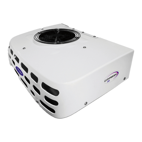
Carrier TRANSICOLD VATNA 200 Release note

GB
VATNA 200 - 300 - 400
DRIVER'S MANUAL
TABLE OF CONTENTS
1. INTRODUCTION .......................................................................................................... 2
2. IDENTIFICATION & NOISE LEVEL ........................................................................................... 2
2.1. Nameplate ...................................................................................................... 2
2.2. Noise Level Charts .............................................................................................. 2
3. SAFETY ................................................................................................................. 2
3.1. Warning and precaution ........................................................................................... 2
3.2. Risks .......................................................................................................... 2
3.3. Warning Stickers Maintenance ..................................................................................... 2
4. OPERATION ............................................................................................................. 2
4.1. Control box description ........................................................................................... 2
4.2. Start the unit on standby .......................................................................................... 3
4.3. Stop the unit .................................................................................................... 3
4.4. Defrost the unit .................................................................................................. 3
5. Maintenance Schedule ..................................................................................................... 4
6. RECOMMENDATIONS ..................................................................................................... 4
6.1. Before loading .................................................................................................. 4
6.2. When loading ................................................................................................... 4
7. RECOMMENDED TRANSPORT TEMPERATURES .............................................................................. 4
8. A.T.P. EUROPE REGULATION EXTRACT ..................................................................................... 5
9. 24H ASSISTANCE ........................................................................................................ 5
62-61954-01 1

GB
1. INTRODUCTION
This guide has been prepared for the operator of Carrier Transicold re-
frigeration units. It contains basic instructions for the daily operation of the
refrigeration unit as well as safety information, troubleshooting tips, and
other information that will help you to deliver the load in the best possible
condition.
Please take the time to read the information contained in this booklet and
refer to it whenever you have a question about the operation of your Car-
rier Transicold unit. This manual refers to the standard model. Some op-
tions may not appear in it, and in such cases you are requested to consult
our Technical Services.
Your refrigeration unit has been engineered to provide long, trouble-free
performance when it is properly operated and maintained. The checks
outlined in this guide will help to minimize on the road problems. In addi-
tion, a comprehensive maintenance program will help to insure that the
unit continues to operate reliably. Such a maintenance program will also
help to control operating costs, increase the unit's working life, and im-
prove performance.
When having your unit serviced, be sure to specify genuine Carrier Tran-
sicold replacement parts for the highest quality and best reliability.
At Carrier Transicold, we are continually working to improve the products
that we build for our customers. As a result, specifications may change
without notice.
2. IDENTIFICATION & NOISE LEVEL
Keep the fold out sheet while reading the instructions.
2.1. NAMEPLATE
Each unit is identified by a nameplate (A) attached to the frame of the
unit. The nameplate identifies the complete model number of the unit, the
Serial Number (B) and some other information.
If a problem occurs, please refer to the information on this plate,
and make a note of the model and Serial Number (B) before
calling for assistance.
This information will be needed when you contact a technician
so that he may properly assist you.
The sticker (C) indicates the noise level in Lwa (sound power
level).
2.2. NOISE LEVEL CHARTS
Unit Maximum Sound Power level
LWA(dB)
VATNA 200/300/400 54
3. SAFETY
3.1. WARNING AND PRECAUTION
This manual contains safety and service instructions to follow
in order to prevent any accident. Some of following stickers
have been placed on the product for your SAFETY.
•NEVER manipulate cab command when driving.
•NEVER intervene on the unit, for any service or
maintenance operation, contact your Carrier service centre.
•NEVER remove safety elements (grill, skin, metal
sheet). If damaged, contact your Service Center for
replacement.
3.2. RISKS
Contact your medical assistance in case of accident.
GENERAL RISKS
Burning with hot and cold test.
Cuttings.
Noise level.
Exhaust gas:
- DO NOT use the unit in a closed space.
Asphyxiation:
- Leave the doors open when working inside the
body.
Risk of slipping going up in the body:
- Ice on the floor.
Risk of slipping going out of the body:
- Leak of refrigerant.
Electrical risks – when connecting and disconnecting
standby plug.
3.3. WARNING STICKERS MAINTENANCE
1. Keep the warning pictograms clean and without any obstruction
material.
2. Clean the pictograms with water and soap and wipe them with soft
fabric.
3. Replace damaged or missing pictograms with new pictograms
available in Carrier network.
4. If a component having a pictogram is replaced by a new one, be sure
that the new component has the right pictogram.
5. Place a warning pictogram by applying it on a dry surface. Press to
external sides to eliminate air bubbles.
4. OPERATION
4.1. CONTROL BOX DESCRIPTION
Operation of these units is automatic.
During temperature pull-down and plate freezing, the unit operates unin-
terrupted.
When the eutectic solution is frozen, the unit shuts down and goes into
pressure-control mode (low pressure).
62-61954-01 2
GB
The minimum operation time for accumulation must be in the region of 9
hours. This time should be increased after defrosting to about 17 hours.
1. Standby operation LED (green).
2. ON/OFF switch.
3. Rearm button.
Used if overload relay opened.
4. Power plug connection.
To connect power supply network .
4.2. START THE UNIT ON STANDBY
BEFORE STARTING
• - On the power network : check that the type of current
corresponds to the characteristics of the unit.
1. Ensure that the ON/OFF switch is switched OFF
position
2. Connect the power network plug to the control box
1. Switch the ON/OFF switch to "ON" position.
The "STANDBY OPERATION" LED is highlighted.
2. Check indicating flag located on front grid for
proper motor rotation
Condenser air flow must be drawn into unit.
If the condenser air drawn out the unit :
• Switch “0” position the “ON/OFF”
switch.
• Disconnect the power plug.
• Reverse the red part by using a screw
driver
In the event of difficulty on start-up, check that
• Network supply is Ok.
• Overload relay is not open by pushing the red 'REARM'
button.
4.2.1. STANDBY GUIDELINE
Standardized exten-
sion cable H.07.RNF
mm2
Unit Fuse 220/3/
50Hz
Fuse
400/3/50Hz
220 volts 400 volts
VATNA 200 15 A 12 A 4 x 2,5 mm² 4 x 2,5 mm²
VATNA 300 20 A 15 A 4 x 4 mm² 4 x 2,5 mm²
VATNA 400 25 A 20 A 4 x 4 mm² 4 x 4 mm²
4.3. STOP THE UNIT
1. Stop the unit by putting the ON/OFF switch to
"OFF" position.
4.4. DEFROST THE UNIT
• In order to obtain the best results from this refrigeration
unit in door-to-door distribution conditions: it is absolutely
necessary to defrost the eutectic plates regularly.
• Any excess of frosting on the plates lowers the efficiency of
the eutectic system.
Do not used water to defrost the eutectic plates.
Too much accumulation of frost on the plates can be avoided
by brushing them down.
Evacuate water that may accumulate on the ground before
restart the unit to avoid a frozen floor.
62-61954-01 3

GB
Figure 1. Example of frosting eutectic plate
1. Stop the unit.
2. Open the cooling box doors.
The plates will defrost naturally.
The defrosting time depends on the frosting and also the
ambiant temperature: keep the cooling box doors opened
from 3 to 12 hours according to the conditions.
5. MAINTENANCE SCHEDULE
VATNA 200/300/400 Service frequencyService Type
Period or
hours interval 12 month 24 months
Service A X X
Service B X
6. RECOMMENDATIONS
This unit is not designed to carry special loads which emit
corrosive gas.
These kind of products can impact unit performance, and
seriously reduce component life time.
Please contact us if such products need to be carried.
• Perform a defrost of the eutectic plates at least once a week to ensure
an optimal efficiency of the eutectic system
Any excess of frosting lowers the efficiency of the eutectic
system.
• It is important to check the temperature of the product being loaded
to ensure that it is at the correct temperature for transport. The
refrigeration unit is designed to maintain the temperature of the product
at the temperature at which it was loaded; it was not designed to cool
a warm product.
6.1. BEFORE LOADING
• Check the condition of the inside and outside of the insulated body, as
well as the door seals.
• Your vehicle should always be clean and well-aired.
6.2. WHEN LOADING
• To be carried out with the unit stopped.
• It is recommended to open doors as little as possible to avoid the intake
of hot air and humidity.
• Select the temperature by means of the thermostat, according to the
transported goods.
• Check the internal temperature of the goods being loaded (using a
probe thermometer).
•• Leave a free space of about 6 to 8 cm between
load and front wall.
• Leave a free space of about 20 cm between
the top of the load and the roof.
• Load product on pallets (gratings) to provide
free air return to unit and improvement product
protection.
• Do not forget to close the doors.
• Before closing the doors, check your load once more and see that
nobody is shut inside the box.
For stationary utilisation, we recommend to place the box in the
shade.
Never leave your unit more than a month without running.
Open the cooling box doors in case of extended stop.
7. RECOMMENDED TRANSPORT TEMPERA-
TURES
Below are some general recommendations on product transport temper-
atures and operating modes for the unit. These are included for reference
only and should not be considered pre-emptive of the Set-point required
by the shipper or receiver. More detailed information can be obtained from
your Carrier Transicold dealer.
PRODUCT Temperature inside
the cooling box*
Ice -20°C (-4°F)
Frozen fruits and vegetables -18°C (-0°F)
Frozen meats and seafood -20°C (-4°F)
Ice cream -25°C (-13°F)
* Given by the Thermometer that indicates the temperature inside the
cooling box.
During delivery cycles that includes frequent stops and door
openings, it is recommended that the unit always be operated
in the continuous run mode to help insure product quality.
It is essential to shutdown the compartment during the periods
when the doors are open, in order to maintain the temperature
of the cargo in the other compartments and keep the unit
operating correctly.
62-61954-01 4

GB
8. A.T.P. EUROPE REGULATION EXTRACT
Approval of vehicles intended for the carriage of perishable goods.
Before putting a refrigerated vehicle into service, it is necessary to have
it approved by the Regional Health Department.
Characteristics of vehicles used for carrying perishable goods; re-
frigeration unit.
The refrigeration unit is an insulated unit with a cooling system which
makes it possible, with a mean outside temperature of +30°C, to lower the
temperature inside the empty body and to maintain this low temperature
in the following way:
Class A: Refrigeration unit furnished with a cooling system whereby a
temperature between +12°C and 0°C inclusive can be chosen.
Class B: Refrigeration unit furnished with a cooling system whereby a
temperature between +12°C and –10°C inclusive can be chosen.
Class C: Refrigeration unit furnished with a cooling system whereby a
temperature between +12°C and –20°C inclusive can be chosen.
The cooling capacity of a unit is determined by a test carried out in one of
the approved testing stations and ratified by an official report.
The "K" factor of bodies intended to be classified as C must be
equal to or lower than 0.4 W/m2 °C.
Signs, identification marks and plates to be attached to refrigeration
units.
Distinguishing plate:
• Standard refrigeration unit Class A → FNA
• Reinforced refrigeration unit Class A → FRA
• Reinforced refrigeration unit Class B → FRB
• Reinforced refrigeration unit Class C → FRC
In addition to the above identification marks, the date (month and year) of
expiry of the approval certificate must be indicated.
Refrigeration plate example:
( 11 = month (November) 2023 = year )
Regularly check the expiry date of the approval certificate.
During transport, the approval certificate or provisional
certificate should be shown on request of qualified agents.
To have an insulated unit approved as a refrigeration unit, an
application to modify the approval certificate should be sent to
the regional health office.
9. 24H ASSISTANCE
At Carrier Transicold we're working hard to give you complete service
when and where you need it. That implies a worldwide network of dealers
and available an emergency service. These service centres are manned
by factory-trained service personnel and backed by extensive parts in-
ventories that will assure you of prompt repair.
Should you encounter a unit problem with your refrigeration unit during
transit, follow your company's emergency procedure or contact the near-
est Carrier Transicold service centre. Consult the directory to locate the
service centre nearest you. This directory may be obtained from your Car-
rier Transicold dealer.
If you are unable to reach a service center, call Carrier Transicold’s
24Hour Assistance: ONE CALL.
In Europe, please use the following free phone numbers from:
AT AUSTRIA 0800 291039
BE BELGIUM 0800 99310
CH SWITZERLAND 0800 838839
DE GERMANY 0800 1808180
DK DENMARK 808 81832
ES SPAIN 900 993213
FR FRANCE 0800 913148
FI FINLAND 0800113221
GB GREAT BRITAIN 0800 9179067
GR GREECE 00800 3222523
HU HUNGARY 06800 13526
IT ITALY 800 791033
IE IRELAND 1800 553286
LU LUXEMBURG 800 23581
RU RUSSIA 810 800 200 31032
NO NORWAY 800 11435
NL THE NETHERLANDS 0800 0224894
PT PORTUGAL 8008 32283
PL POLAND 00800 3211238
SE SWEDEN 020 790470
From other countries / Direct: +32 11 8791 00
In Canada or United States, call: 1 – 800 – 448 1661
When calling, please have the following information ready for fastest
service:
• Your name, the name of your company, and your location.
• A telephone number where you can be called back.
• Refrigeration unit model and serial number.
• Box temperature, Set-point and product.
• Brief description for the problem you are having and what you have
already done to correct the problem.
We will do everything we can to get your problem taken care of and get
you back on the road.
62-61954-01 5
This manual suits for next models
2
Table of contents
Other Carrier TRANSICOLD Cooling Box manuals
Popular Cooling Box manuals by other brands

Mobicool
Mobicool MT08 Operating and safety instructions

Crivit
Crivit REK 230 E3 Operation and safety notes

Dometic GROUP
Dometic GROUP Waeco TropiCool TB-W203 operating manual

Hessaire
Hessaire 36X370-N instruction manual

Dometic
Dometic mobilCooler RC1500 operating instructions

Whynter
Whynter CHC-1228D instruction manual