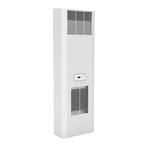
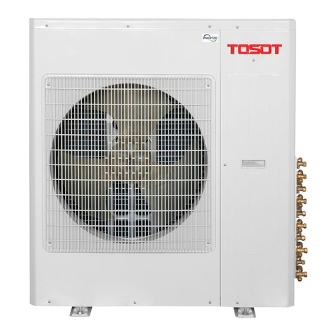
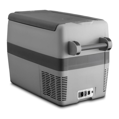
Rittal SK 3178800 User manual

Enclosure cooling unit
Assembly and operating instructions
SK 3178800
SK 3178801
SK 3179800
SK 3179801
SK 3184800
SK 3184840

Preface
EN
2Rittal enclosure cooling unit
Preface
Dear Customer!
Thank you for choosing a "Blue e+" enclosure cooling
unit (referred to hereafter as "cooling unit") from Rittal.
Yours
Rittal GmbH & Co. KG
Rittal GmbH & Co. KG
Auf dem Stützelberg
35745 Herborn
Germany
Phone: +49(0)2772 505-0
Fax: +49(0)2772 505-2319
E-mail: info@rittal.de
www.rittal.com
www.rittal.de
We are always happy to answer any technical questions
regarding our entire range of products.
DE

Rittal enclosure cooling unit 3
Contents
EN
Contents
1 Notes on documentation .................. 4
1.1 CE labelling................................................... 4
1.2 Storing the documents.................................. 4
1.3 Symbols used in these operating
instructions ................................................... 4
1.4 Other applicable documents ......................... 4
2 Safety instructions ............................ 5
2.1 General safety instructions ............................ 5
2.2 Safety instructions for transportation............. 5
2.3 Safety instructions for assembly.................... 5
2.4 Safety instructions for installation .................. 5
2.5 Safety instructions for operation.................... 5
2.6 Safety instructions for maintenance............... 5
2.7 Operating and technical staff......................... 5
2.8 Other dangers when using the cooling unit ... 5
2.9 IT safety instructions ..................................... 5
2.9.1 Measures for products and systems ..................... 6
3 Product description .......................... 7
3.1 Functional description and components........ 7
3.1.1 Function ............................................................... 7
3.1.2 Components ........................................................ 8
3.1.3 Control ................................................................. 8
3.1.4 Safety devices ...................................................... 8
3.1.5 Condensation ....................................................... 8
3.1.6 Filter mats ............................................................ 9
3.1.7 Door limit switch ................................................... 9
3.2 Intended use, foreseeable misuse ................. 9
3.3 Supply includes........................................... 10
4 Transport and handling .................. 11
4.1 Delivery....................................................... 11
4.2 Unpacking .................................................. 11
4.3 Transport .................................................... 11
5 Installation ...................................... 13
5.1 Safety instructions....................................... 13
5.2 Siting location requirements ........................ 13
5.3 Assembly procedure ................................... 13
5.3.1 Assembly instructions ......................................... 13
5.3.2 Mounting options ............................................... 14
5.3.3 Make a mounting cut-out in the enclosure .......... 14
5.3.4 External mounting of the cooling unit .................. 15
5.3.5 Internal mounting of the cooling unit ................... 16
5.3.6 Connect the condensate water discharge .......... 20
5.4 Electrical connection ................................... 21
5.4.1 Notes on electrical installation ............................. 21
5.4.2 Install the power supply ...................................... 23
5.4.3 Connect the alarm relay ...................................... 24
5.4.4 Interfaces ........................................................... 24
6 Commissioning .............................. 25
7 Operation ....................................... 26
7.1 Control via the display................................. 26
7.2 General information about programming ..... 26
7.3 Updater program ........................................ 26
7.4 Setting options via the display .................... 27
7.4.1 Selecting a control mode .................................... 27
7.4.2 Setting the target temperature ............................ 27
7.4.3 Setting the unit ................................................... 28
7.4.4 Launching test mode .......................................... 28
7.4.5 Manually acknowledge a system message ......... 28
7.4.6 Programming overview ....................................... 29
7.4.7 Parallel device control ......................................... 29
7.4.8 Evaluate system messages ................................ 29
7.5 Rittal Scan & Service app ........................... 29
7.5.1 General .............................................................. 29
7.5.2 Configuration ...................................................... 30
7.5.3 Technical Guide ................................................. 31
7.5.4 Product informationen ........................................ 31
7.5.5 Services and spare parts .................................... 31
7.5.6 Fast Copy .......................................................... 31
7.6 List of system messages ............................ 32
8 Inspection and maintenance ........... 35
8.1 Safety instructions for maintenance work ... 35
8.2 Notes on the refrigerant circuit ................... 35
8.3 Maintenance work on the cooling unit ........ 35
8.4 Compressed air cleaning............................ 35
8.4.1 Removing an internally mounted unit .................. 35
8.4.2 Removing an externally mounted unit ................. 36
8.4.3 Removing the cover ........................................... 36
8.4.4 Cleaning the components with compressed air .. 37
8.4.5 Re-assembling the cooling unit ........................... 38
9 Storage and disposal ...................... 39
10 Technical specifications .................. 40
11 List of spare parts ........................... 44
12 Drawings ........................................ 46
12.1 Representation of mounting cut-outs ......... 46
12.2 External and internal mounting dimensions
(SK 317880x – width 300 mm) ................... 47
12.3 External and internal mounting dimensions
(SK317980x – width 300 mm) ................... 48
12.4 External and internal mounting dimensions
(SK31848x0 – width 400 mm) ................... 49
13 Accessories .................................... 50
14 Customer service addresses .......... 51
15 Compact service information .......... 55

1 Notes on documentation
EN
4Rittal enclosure cooling unit
1 Notes on documentation
1.1 CE labelling
Rittal GmbH & Co. KG confirms the conformity of the
cooling unit with the European Union's Machinery Direc-
tive 2006/42/EC and EMC Directive 2014/30/EC. A cor-
responding declaration of conformity has been issued
and enclosed with the unit. These are the original oper-
ating instructions.
1.2 Storing the documents
The assembly and operating instructions as well as all
other applicable documents are an integral part of the
product. They must be issued to everyone who works
with the unit and must always be available and on hand
for operating and maintenance personnel.
1.3 Symbols used in these operating in-
structions
The following symbols are used in this documentation:
This symbol indicates an "action point" and shows that
you should perform an operation or procedure.
1.4 Other applicable documents
Paper copies of the assembly and operating instructions
are available for the unit types described here and are
enclosed with the equipment.
We cannot accept any liability for damage associated
with failure to observe these instructions.
Please also observe the instructions for any accesso-
ries used.
Warning!
A dangerous situation which may cause
death or serious injury if the instructions
are not followed.
Caution!
A dangerous situation which may lead to
(minor) injuries if the instructions are not
followed.
Note:
Important notices and indication of situations
which may result in material damage.

Rittal enclosure cooling unit 5
2 Safety instructions
EN
2 Safety instructions
2.1 General safety instructions
Please observe the following general safety instructions
for the installation and operation of the system:
– Always wear the required personal safety equipment
when working on this device.
– Before removing the hood, allow the unit to cool for at
least 10 minutes to eliminate the risk of burns from hot
surfaces.
– Please do not make any changes to the cooling unit
that are not described in these operating instructions
or other applicable assembly and operating instruc-
tions.
– The products should only be combined and operated
with the prescribed Rittal system accessories.
– Other than these general safety instructions, it is also
vital to observe the specific safety instructions when
carrying out the tasks described in the following chap-
ters.
2.2 Safety instructions for transportation
– Please observe the maximum permissible weight to be
lifted by one person. Use suitable lifting devices, if
needed.
– Cooling units must be transported in an upright posi-
tion and secured to prevent them from tipping over.
– Shipping braces (such as a structure made from
square timbers or boards) must be used when trans-
porting cooling units already mounted on the enclo-
sure. These braces support the cooling unit and pre-
vent it from slipping in case of impact.
– Use a sufficiently large pallet to prevent it tipping over.
– If the cooling unit has been mounted on a door, close
the door and keep it closed during transportation.
2.3 Safety instructions for assembly
– During assembly, the cooling unit is at risk of dropping
through the mounting cut-out.
– Do not assemble and re-activate the device until it is
completely dry.
2.4 Safety instructions for installation
– Please be sure to observe the applicable regulations
governing electrical installations of the country in
which the device is installed and operated as well as
national regulations for accident prevention. Please
also observe any internal company regulations, such
as work, operating and safety regulations.
– The connection regulations of the appropriate power
supply company are to be followed. Otherwise, there
is risk of injury from electric shock if the connection to
the unit is defective or connected incorrectly in any
way.
– Do not strip too much insulation from the connection
cable, otherwise the admissible clearance/creepage
distances from the terminal point may not be met.
– The cooling unit must be connected to the mains via
an all-pole disconnect to overvoltage category III (IEC
61058-1).
– Pin 4 on the signal connector should not be used. Oth-
erwise, the admissible clearance/creepage distance
between the alarm relay and door contact connec-
tions will not be met.
2.5 Safety instructions for operation
– The operational safety of the cooling unit is only war-
ranted if used as intended. The technical specifica-
tions and limit values stated must not be exceeded un-
der any circumstances. In particular, this applies to the
specified ambient temperature range and IP protec-
tion category.
– Operating the cooling unit in direct contact with water,
aggressive materials or inflammable gases and va-
pours is prohibited.
2.6 Safety instructions for maintenance
– The device must only be cleaned by trained special-
ists. De-energise the device prior to cleaning.
– Never use flammable liquids for cleaning.
2.7 Operating and technical staff
– The assembly, installation, commissioning, mainte-
nance and repair of this cooling unit may only be per-
formed by qualified, trained personnel.
– Only properly instructed personnel may operate a
cooling unit with the system operational.
– Children and persons with limited cognitive/coordina-
tive abilities must not operate, maintain or clean the
unit or be allowed to use it as a toy.
2.8 Other dangers when using the cooling
unit
When installing the cooling unit (see section 5 "Installa-
tion"), there is a risk that the enclosure could become
unbalanced and tip over.
In such cases, the enclosure should be bolted to the
floor as a precaution.
If the air inlet or outlet of the cooling unit is obstructed,
there is a risk of air short-circuits, resulting in inadequate
climate control.
Please ensure that the electronic assemblies in the en-
closure are installed in accordance with section 5.3.1
"Assembly instructions".
Where applicable, use suitable components to divert
the air.
Please observe the prescribed minimum distances at
the installation site as outlined in section 5.3.1 "As-
sembly instructions".
2.9 IT safety instructions
To ensure the availability, confidentiality and integrity of
data, products, networks and systems must be protect-
ed against unauthorised access.

2 Safety instructions
EN
6Rittal enclosure cooling unit
Such protection can be achieved only with organisation-
al and technical measures. To satisfy the increased safe-
ty requirements, Rittal recommends the observance of
the following measures. Furthermore, more detailed in-
formation can be found on the websites of Bundesamt
für Sicherheit in der Informationstechnik (Federal Office
for IT Security – BSI).
2.9.1 Measures for products and systems
Embed products and systems not in public net-
works.
Make sure that the system is only operated in protect-
ed networks.
Configure the firewall
To protect your networks, and the embedded prod-
ucts and systems against external effects, configure a
firewall.
Also deploy a firewall for segmentation of a network or
to isolate a controller.
Consider defence-in-depth mechanisms during
the planning phase
Consider defence-in-depth mechanisms for your sys-
tem planning.
Defence-in-depth mechanisms cover several levels of
mutually coordinated security measures.
Restrict access authorisations
Restrict access authorisations to networks and sys-
tems to only persons that need an authorisation.
Protect accesses
Do not use the default passwords; instead, use se-
cure, long passwords containing numbers, a mix of
upper case and lower case letters, symbols and no
repetitions.
Create random passwords with a password manager.
Deploy the current firmware version
Ensure that the current Rittal firmware is deployed on
all devices.
The firmware can be downloaded from the associated
product pages in the Internet.
Observe the associated Release Notes for new firm-
ware versions.
Deploy current security software
To identify and eliminate security threats, such as vi-
ruses, trojans and other malicious software, security
software should be installed on all PCs and kept up-
to-date.
Deploy whitelist tools to monitor the device context.
Deploy an intrusion-detection system to validate the
communication of your system.
Perform regular threat analyses
Rittal recommends that you perform regular threat
analyses.
The threat analyses allow you to determine whether
your adopted measures are effective.
Protect USB ports against access
USB ports must be protected against physical access.
Ensure that no unauthorised persons have access to
USB ports.
Sensitive data can be read for an unauthorised access
to USB ports.

Rittal enclosure cooling unit 7
3 Product description
EN
3 Product description
3.1 Functional description and components
3.1.1 Function
There are two separate cooling circuits installed in the
cooling unit.
– One conventional refrigerant circuit (compression sys-
tem), and
– One heat pipe integrated into the condenser and
evaporator coil.
Fig. 1: Cooling circuit
Key
1 Compressor
2 Condenser (dual version)
3 Expansion valve
4 Evaporator coil (dual version)
5 Refrigerant circuit with heat pipe
6 Refrigerant circuit with compression system
7 Internal circuit
8 External circuit
9 Dryer/collector
10 Internal fan
11 External fan
In both cooling circuits, the individual components are
connected with pipes in which the refrigerant R513A is
circulating. This refrigerant is very environmentally friend-
ly, thanks to the following properties:
– Does not deplete the ozone layer (ozone destruction
potential ODP = 0)
– Global Warming Potential (GWP): 631
Refrigerant circuit with compression system
The refrigerant circuit with compression system is com-
prised of the following four main components:
1. Evaporator coil
2. Compressor
3. Condenser
4. Expansion valve
The evaporator coil fan draws hot air from the enclosure
in the internal circuit of the cooling unit and passes it
over the evaporator coil. After the evaporator coil, the
cooled air is fed back into the enclosure via the outlet
opening.
The air is cooled down by evaporating the refrigerant in
the evaporator coil. The refrigerant vapour is transported
by the compressor in the external circuit of the cooling
unit to the condenser. There, the refrigerant condenses
and becomes a liquid. The heat produced is dissipated
by the condenser fan. The downstream electronic ex-
pansion valve reduces the high pressure of the refriger-
ant, and the refrigerant is then fed back into the evapo-
rator coil.
Both the compressor and the two fans in the cooling unit
are activated via an inverter. This makes it possible to
control these components, so that the fan and compres-
sor may be activated for a longer time but at a lower out-
put and improved efficiency.
Refrigerant circuit with heat pipe
The additional second refrigerant circuit operates with-
out a compressor, expansion valve or other control ele-
ments, and is integrated into the evaporator coil and
condenser as a heat pipe.
The refrigerant inside the heat pipe (R513A) absorbs
thermal energy from the intake of enclosure air and
evaporates. The gaseous refrigerant then rises through
the pipeline until it reaches the condenser. The refriger-
ant is cooled down again in the condenser (provided Tu
< Ti), and the heat released is emitted into the environ-
ment. Gravity then causes the liquid refrigerant to flow
back down the pipelines. The whole cycle begins again.
1
11 9
10
5
6
2
3
4
5
6
8
7

3 Product description
EN
8Rittal enclosure cooling unit
3.1.2 Components
Fig. 2: Main components of cooling unit (SK 317880x/
SK 317980x)
Fig. 3: Main components of cooling unit (SK 31848x0)
Key fig. 2 and fig. 3
1 Louvred grille
1a Top louvred grille
1b Bottom louvred grille
2 Service label
3 Air outlet, outside
4 Display including NFC interface
5 Air inlet, outside
6Cover
7 Electrical connections and interfaces
8 Air inlet, inside
9 Mounting point, potential equalisation
10 Rating plate
11 Rear panel
12 Mounting point, IoT interface
13 Air outlet, inside
14 Foamed-in seal
15 Thread for eyebolt
3.1.3 Control
Rittal enclosure cooling units are fitted with a controller
for setting the functions of the cooling unit.
Operation using this controller is described in section 7
"Operation".
3.1.4 Safety devices
– The cooling units are equipped with various features to
prevent inadmissible pressure increases in the cooling
cycle. If an unusually high pressure nevertheless oc-
curs, the compressor may be temporarily and auto-
matically deactivated via a safety device. Once the
pressure drops back below the admissible pressure,
the unit will automatically resume operation.
– Temperature monitoring prevents the evaporator coil
from icing over. If there is a risk of icing, the compres-
sor switches itself off and automatically switches itself
back on again at higher temperatures.
– The compressor is monitored and protected by the in-
verter to prevent overloading.
– The fans have a built-in overload protection with auto-
matic reset.
– In order to allow a reduction of pressure inside the
compressor and hence a safe restart, once it has been
switched off (e.g. upon reaching the set temperature
via the door limit switch function or via de-energising),
the device will switch back on with a delay of 180 sec-
onds.
– The device has a floating contact on the connection
pins on terminals 2 and 3 of the signal connector (X3),
via which system messages from the device may be
polled, e.g. using a PLC.
3.1.5 Condensation
At high levels of humidity and low temperatures inside
the enclosure, condensate water may form on the evap-
orator coil.
All cooling units except SK 3178801 and SK 3179801
have automatic electric condensate evaporation. The
thermal component used for this purpose is based on
self-regulating PTC technology. Condensate water aris-
ing on the evaporator coil is collected in a tank in the ex-
ternal circuit of the cooling unit, and partially evaporated
via the airflow. When the water level rises, the water en-
ters the PTC thermal component and is evaporated
(through-flow heater principle). The water vapour
streams out of the cooling unit with the airflow from the
external fan.
If there is a short-circuit in the PTC element, the separate
PTC fuse will trip and the condensate can be drained off
via the safety overflow.
The condensate is routed out of the unit via the evapo-
rator tray overflow. For this purpose, a hose may be con-
nected to the condensate nozzle (see section 5.3.6
"Connect the condensate water discharge").
6
7
8
5
4
3
2
1
9
10
11
12
13
14
6
7
15
8
5
4
3
2
1a
1b
9
10
11
12
13
14

Rittal enclosure cooling unit 9
3 Product description
EN
3.1.6 Filter mats
For dry, coarse dust and lint in the ambient air, we rec-
ommend installing an additional PU foam filter mat (avail-
able as an accessory) in the cooling unit. Depending on
the incidence of dust, you will need to replace the filter
mat from time to time (see section 7.5.2 "Configura-
tion").
For oily ambient air, we recommend the use of metal fil-
ters (also available as an accessory). These may be
cleaned with suitable detergents and reused.
3.1.7 Door limit switch
The cooling unit may be operated with a floating door
limit switch connected. The door limit switch is available
as accessory from Rittal.
The door limit switch function causes the fans and the
compressor in the cooling unit to gradually slow down
and then switch off after approximately 15 seconds
when the enclosure door is opened (contacts 5 and 6
closed). This prevents the formation of condensate wa-
ter inside the enclosure while the enclosure door is
open. In order to prevent damage to the unit, it is
equipped with an ON delay: The evaporator fan will cut
in again after a delay of a few seconds on closure of the
door.
Please note that no external voltage may be applied to
the door contacts (connection clamps 5 and 6).
3.2 Intended use, foreseeable misuse
The cooling unit is intended exclusively for cooling
closed control cabinets as well as for professional use in
accordance with DIN EN 61000-3-2. Any other use is
not permitted.
The cooling unit is intended for indoor and semi-outdoor
use as standard. Semi-outdoor use is defined as fol-
lows:
– Siting in a roofed outdoor area.
The cooling unit is protected from the direct impacts
of weather conditions such as precipitation or perma-
nent sunlight.
– Always use within the admissible temperature range.
– The device is secure from unauthorized public access.
The unit must not be installed and operated in locations
which are accessible to the general public (see DIN EN
60335-2-40, paragraph 3.119).
The unit is designed solely for stationary use.
The cooling unit must not be used in environments with
conductive, flammable and explosive dusts.
These include:
– Graphite dusts
– Metal dusts
– Cereal dusts
– Wood dusts
– Textile fibres and lint
The cooling unit is state of the art and built according to
recognised safety regulations. Nevertheless, improper
use can pose a threat to the life and limb of the user or
third parties, or result in possible damage to the system
and other property.
Consequently, the cooling unit must only be used prop-
erly and in a technically sound condition! Any malfunc-
tions which impair safety should be rectified immediate-
ly.
Proper use also includes the observance of the docu-
mentation provided, and compliance with the inspection
and maintenance conditions.
Rittal GmbH & Co. KG is not liable for any damage which
may result from failure to comply with the documenta-
tion provided. The same applies to failure to comply with
the valid documentation for any accessories used.
Inappropriate use may be dangerous. Examples of inap-
propriate use include:
– Use of the cooling unit over long periods with the en-
closure open.
– Use of impermissible tools.
– Improper operation.
– Improper rectification of malfunctions.
– Use of accessories not approved by Rittal GmbH &
Co. KG.

3 Product description
EN
10 Rittal enclosure cooling unit
3.3 Supply includes
Description Illustration SK 317880x
SK 317980x
SK 3184800
SK 3184840
Enclosure cooling unit 1x
Shipping bag with 1x
– Assembly and installation instructions 1x
– Grub screw M8x40 4x
– Corner bracket with M8 nut 4x
–Springclip 2x
– Locator clip with cable fastening 1x 2x
– Signal connector 1x
–Powerplug 1x
– Sealing tape 10x10 mm for installation 1x 1.74 m 1x 2.7 m
Tab. 1: Supply includes

Rittal enclosure cooling unit 11
4 Transport and handling
EN
4 Transport and handling
4.1 Delivery
The cooling unit is supplied in one packaging unit.
Check the packaging carefully for signs of damage.
Traces of oil on damaged packaging indicate a loss of
refrigerant and/or a leak in the cooling unit. Any pack-
aging damage may be the cause of a subsequent
functional failure.
4.2 Unpacking
Remove the packaging materials from the cooling unit.
Check the cooling unit for any damage that may have
occurred during transport.
Check the supply contents for completeness (see sec-
tion 3.3 "Supply includes").
4.3 Transport
Cooling unit types SK 317880x/SK 317980x weigh up
to 13 kg. Cooling unit types SK 31848x0 weigh up to
27 kg.
An M12 thread is provided on top of the cover on unit
types SK 31848x0 for screw-fastening a Rittal eyebolt
(e.g. belonging to an enclosure). The cooling unit is read-
ily transported with the aid of lifting gear and an indoor
crane.
Fig. 4: Thread for eyebolt on top of the cover (only unit type
SK 31848x0)
Key
1Cover
2M12thread
Before transporting by crane, please ensure that the
lifting gear and crane have sufficient load capacity to
transport the cooling unit safely.
Never allow anyone to stand beneath a suspended
load, even for a short time, during transportation by
crane.
Protect the lifting gear on the crane hook from load de-
flection, because the load's centre of gravity may be
off-centre.
First position the cooling unit close to the installation
site and protect from accidentally being knocked over.
Transport of a fitted cooling unit
Shipping braces (such as a structure made from
square timbers or boards) must be used when trans-
porting cooling units already mounted on the enclo-
sure – fig. 5 and fig. 6).
These braces support the cooling unit and prevent it
from slipping in case of impact.
To prevent paint abrasion, please place bubble wrap
or similar between the square timbers and the cooling
unit.
Use a sufficiently large pallet to prevent it tipping over.
If the cooling unit has been mounted on a door, close
the door and keep it closed during transportation.
Note:
After unpacking, the packaging materials
must be disposed of in an environmentally
friendly way.
Note:
Damage and other faults, e.g. incomplete de-
livery, should be reported immediately, in
writing, to the shipping company and to
Rittal GmbH & Co. KG.
Caution!
Please note the maximum weights that
may be lifted by individuals. It may be
necessary to use lifting gear.
Note:
An eyebolt with M12 thread may be ordered
as an accessory from Rittal (see section13
"Accessories").
2
1

4 Transport and handling
EN
12 Rittal enclosure cooling unit
Fig. 5: External mounting of the shipping braces
Key
1 Fitted cooling unit
2 Bubble wrap
3 Supporting structure
4 Pallet underneath the cooling unit
Fig. 6: Internal mounting of the shipping braces
Key
1 Fitted cooling unit
2 Bubble wrap
3 Supporting structure
4 Pallet underneath the cooling unit
4
3
2
1
4
3
1
2

Rittal enclosure cooling unit 13
5 Installation
EN
5 Installation
5.1 Safety instructions
– Work on electrical systems or equipment may only be
carried out by an electrician or by trained personnel
under the guidance and supervision of an electrician.
All work must be carried out in accordance with elec-
trical engineering regulations.
– The cooling unit may only be connected after the
aforementioned personnel have read this information!
– Use only insulated tools.
– Follow the connection regulations of the appropriate
electrical supply company. Otherwise, there is risk of
injury from electric shock if the connection to the unit
is defective or connected incorrectly in any way.
– The cooling unit must be connected to the mains via
an all-pole disconnecting device to overvoltage cate-
gory III (IEC 61058).
– Do not strip too much insulation from the connection
cable, otherwise the admissible clearance/creepage
distances from the terminal point may not be met.
– Pin 4 on the signal connector should not be used. Oth-
erwise, the admissible clearance/creepage distance
between the alarm relay and door contact connec-
tions will not be met.
– The cooling unit is not de-energised until all of the volt-
age sources have been disconnected!
– Do not assemble and re-activate the device until it is
completely dry.
Please note the maximum weights that may be lifted
by individuals. It may be necessary to use lifting gear.
During assembly, the cooling unit is at risk of dropping
through the mounting cut-out.
Always wear the required personal safety equipment
when working on this device.
Please be sure to observe the applicable regulations
governing electrical installations of the country in
which the device is installed and operated as well as
national regulations for accident prevention. Please
also observe any internal company regulations, such
as work, operating and safety regulations.
The technical specifications and limit values stated
must not be exceeded under any circumstances. In
particular, this applies to the specified ambient tem-
perature range and IP protection category.
5.2 Siting location requirements
When choosing the installation site for the enclosure,
please observe the following:
– The site for the enclosure, and hence the positioning
of the cooling unit, must be carefully selected so as to
ensure good ventilation (distance between cooling
units at least 200 mm, distance from wall see distance
"y" in fig. 7 or tab. 2).
– The cooling unit must be installed and operated with a
maximum deviation of 2° from the vertical.
– The installation site must be free from excessive dirt,
aggressive ambient conditions and moisture.
– The ambient temperature must not exceed 60 °C.
– It must be possible to fit a condensate water discharge
(see section 5.3.6 "Connect the condensate water
discharge").
– The mains connection data as stated on the rating
plate of the cooling unit must be guaranteed.
Electromagnetic interference (EMI)
– Interfering electrical installations (high frequency) must
be avoided.
– Signal cables must be laid separately from live cables.
5.3 Assembly procedure
5.3.1 Assembly instructions
Before starting assembly, please ensure that the fol-
lowing tools are available:
–AllenkeySW4
– Open-end spanner SW13
– Phillips-head screwdriver
Before assembling, please ensure that the enclosure
is sealed on all sides (IP 54). Increased condensation
will occur later during operation if the enclosure is not
airtight.
If applicable, additionally fit a door limit switch (such as
4127010) to the enclosure which switches off the
cooling unit when the enclosure door is opened to pre-
vent excessive condensation (see section 3.1.7 "Door
limit switch").
Please ensure that the electronic assemblies in the en-
closure allow the even circulation of air.
Measure the distance "x" (fig. 7) from electronic com-
ponents and other installed equipment inside the en-
closure so that the required air circulation is not
obstructed.
Fig. 7: Air circulation inside the enclosure
x
y

5 Installation
EN
14 Rittal enclosure cooling unit
Under no circumstances should the air inlet and outlet
openings of the cooling unit be obstructed. Only in this
way is it possible to ensure that the maximum cooling
output is available.
Please ensure that the cold airflow from the cooling
unit is not directed at active components.
Fig. 8: Never direct the cold airflow at active components (ex-
ample illustration)
If appropriate, install components to divert the air.
When installing in a dismantled door or side panel,
please ensure that it cannot fall over when installing
the cooling unit in the mounting cut-out.
5.3.2 Mounting options
Essentially, there are two options for fitting the cooling
unit on an enclosure door or side panel.
Fig. 9: Mounting options (example illustration)
Key
1 External mounting
2 Internal mounting
– External mounting: All of the cooling unit is outside the
enclosure.
– Internal mounting: All of the cooling unit is inside the
enclosure. Only the louvred grilles project on the out-
side.
Your chosen installation option will ultimately depend on
how much space you require inside and outside of the
enclosure. The various mounting options have no influ-
ence on the cooling output of the cooling unit, which re-
mains the same in all cases.
– If there are a large number of components installed in-
side the enclosure, external mounting of the cooling
unit may be appropriate. In such cases, the space in-
side the enclosure may be insufficient for internal
mounting, or it may not be possible to guarantee ade-
quate cooling of all components inside the enclosure.
– If the space surrounding the enclosure is limited, in-
ternal mounting may be appropriate to keep essential
escape routes clear.
5.3.3 Make a mounting cut-out in the enclosure
In order to mount the cooling unit on the enclosure, a
suitable mounting cut-out must be made in the door or
side panel of the enclosure.
Model No. Dimensions x and y [mm]
SK 317880x 100
SK 317980x 125
SK 31848x0 125
Tab. 2: Dimensions "x" and "y" [mm]
Note:
The pictures in this chapter illustrate the in-
stallation of the cooling unit in an enclosure
door. Installation in a side panel is carried out
in the same way.
Note:
The dimensions of the mounting cut-outs
can be found in section 12.1 "Representa-
tion of mounting cut-outs".
1 2

Rittal enclosure cooling unit 15
5 Installation
EN
Using the diagrams in section12.1 "Representation of
mounting cut-outs", calculate the required dimensions
for your mounting cut-out.
Make the required mounting cut-out.
Carefully deburr the cut-out to prevent injuries caused
by sharp edges.
5.3.4 External mounting of the cooling unit
Screw two grub screws into the blind rivet nuts in the
corners at the bottom rear of the cooling unit (torque
= 5 Nm).
Fig. 10: Screw the lower grub screws into place
For SK 317880x and SK 317980x: Insert a locator clip
at the top left so that it latches securely home into the
cooling unit.
Fig. 11: Insert the locator clip (for SK 317880x and
SK 317980x)
For SK 31848x0: Insert two locator clips at the top so
that they latch securely home into the cooling unit.
Fig. 12: Inserting the locator clips (for SK 317980x)
These clips will prevent the cooling unit from falling out
of the mounting cut-out later on before it is properly
secured using the corner brackets with nuts.
Lift up the cooling unit, and initially set it down with the
two outside lower grub screws resting on the enclo-
sure door or side panel.
Fig. 13: Position the cooling unit and push it home
For SK 317880x and SK 317980x: Push the cooling
unit into the mounting cut-out at the top until the clip
behind the cut-out audibly latches home.
Caution!
There is a risk of injury on sharp cut-outs
which have not been properly deburred,
especially while mounting the cooling
unit.
Note:
In these instructions, we have only provided
images of units SK 31848x0 in cases where
assembly deviates from the illustration given.
1.
2.
CLICK!
Note:
In the subsequent step, take care to ensure
that the cooling unit only rests on the grub
screws, never on the seal, otherwise the seal
could become damaged.
1.
2. CLICK!

5 Installation
EN
16 Rittal enclosure cooling unit
Fig. 14: Lock home the clip behind the cut-out (for SK 317880x
and SK 317980x)
For SK 31848x0: Push the cooling unit into the mount-
ing cut-out at the top until both clips behind the cut-
out audibly lock home.
Fig. 15: Lock home the clips behind the cut-out (for
SK 31848x0)
Similarly, at the top, screw two grub screws into the
blind rivet nuts in the rear corners of the cooling unit
(torque = 5 Nm).
Fig. 16: Screw the upper grub screws into place
Attach the two corner brackets with nuts to the grub
screws at the top and secure (torque = 5 Nm).
Fig. 17: Secure with corner brackets at the top
In the same way, attach the two corner brackets with
nuts onto the grub screws at the bottom and secure
(torque = 5 Nm).
Fig. 18: Secure with corner brackets at the bottom
Insert one spring clip half-way up the rear of the cool-
ing unit on both the left and right.
Fig. 19: Secure with spring clips
5.3.5 Internal mounting of the cooling unit
SK 317880x and SK 317980x
Grasp hold of the recessed handles on the left and
right of the louvred grille and pull the louvred grille gen-
tly upwards out of the device mounting clips.
CLICK!
CLICK!
CLICK!

Rittal enclosure cooling unit 17
5 Installation
EN
Fig. 20: Pull off the louvred grille (top)
Next, pull the louvred grille out of the mounting clips at
the bottom as well and pull it forwards a maximum of
100 mm away from the device, taking care to hold it
as straight as possible.
Fig. 21: Pull off the louvred grille and the connector
Disconnect the connector on the display.
Place the louvred grille down in a safe place.
SK 31848x0
Press the outside buttons on the right and left of the
lower louvred grille and pull it away from the device.
Fig. 22: Pull off the lower louvred grille
Pull the top louvred grille away from the mounting
clips, taking care to hold it as straight as possible.
Fig. 23: Pull off the top louvred grille.
Set the top louvred grille down in a safe place.
Disconnect the connector on the display.
Fig. 24: Pull off the connector
Carefully remove the connection cable from the
groove in the lower louvred grille.
Fig. 25: Remove the connection cable
Release the range limiters of the lower louvred grille
from their holders on the left and right of the device.
1.
2.
1.
1.
2.
3.

5 Installation
EN
18 Rittal enclosure cooling unit
Fig. 26: Release the range limiters
Next, pull the lower louvred grille upwards at an angle
out of the bottom holders and set it down in a safe
place.
Fig. 27: Pull off the lower louvred grille.
All device versions
Apply sealing tape all around the front of the cooling
unit.
Fig. 28: Apply sealing tape
Start in the top centre of the device to ensure that the
joint edge is not at the bottom of the device where wa-
ter from outside could penetrate.
Fig. 29: Position the joint edge at the top
For SK 317880x and SK 317980x: At the top left, in-
sert a locator clip so that it latches securely home into
the cooling unit.
Fig. 30: Latch home the locator clip (for SK 317880x and SK
317980x)
For SK 31848x0: Insert two locator clips at the top so
that they latch securely home into the cooling unit.
Fig. 31: Latch home the locator clips (for SK 31848x0)
These clips will prevent the cooling unit from falling out
of the mounting cut-out later on before it is properly
secured with the grub screws.
1.
2.
1.
2.
✔
✖
Top
Bottom
CLICK!
CLICK!
1.
2.
CLICK!
CLICK!
CLICK!
1.
2.

Rittal enclosure cooling unit 19
5 Installation
EN
At the bottom, screw two grub screws into the blind
rivet nuts in the front corners of the cooling unit (torque
= 5 Nm).
Fig. 32: Screw the bottom grub screws into place
Lift up the cooling unit, and set it down initially with the
two inside lower grub screws resting on the enclosure
door or side panel.
Fig. 33: Position the cooling unit and push it into place
For SK 317880x and SK 317980x: Push the cooling
unit into the mounting cut-out at the top until the clip
behind the cut-out audibly latches home.
Fig. 34: Latch home the clip behind the cut-out (for SK
317880x and SK 317980x)
For SK 31848x0: Push the cooling unit into the mount-
ing cut-out at the top until the clips behind the cut-out
audibly latch home.
Fig. 35: Lock home the clips behind the cut-out (for
SK 31848x0)
Similarly, at the top, screw two grub screws into the
blind rivet nuts at the front corners of the cooling unit
(torque = 5 Nm).
Fig. 36: Screw the top grub screws into place
Attach the two corner brackets with nuts to the
threaded grub screws at the top and secure (torque =
5 Nm).
Fig. 37: Secure with corner brackets at the top
CLICK!
CLICK!
CLICK!

5 Installation
EN
20 Rittal enclosure cooling unit
In the same way, insert the two corner brackets with
nuts onto the grub screws at the bottom and secure
(torque = 5 Nm).
Fig. 38: Secure with corner brackets at the bottom
Insert one spring clip half-way up the rear of the cool-
ing unit on both the left and right.
Fig. 39: Secure with spring clips
For SK 317880x and SK 317980x: Release the locator
clip at the top left and, where applicable, insert it into
the rear of the device for cable fixing and routing.
Fig. 40: Release the locator clip (for SK 317880x and
SK 317980x)
For SK 31848x0: Release the two locator clips at the
top and insert one of the clips into the rear of the de-
vice for cable fixing and routing. The second clip may
likewise be inserted into the top rear of the device.
Fig. 41: Release the locator clips (for SK 31848x0)
SK 317880x and SK 317980x
Bring the louvred grille close to the device.
Connect the connector at the bottom of the display.
Place the louvred grille onto the mounting clips at the
top and bottom, keeping it as straight as possible, and
press it fully onto the cooling unit.
SK 31848x0
Holding the lower louvred grille at an angle from
above, engage it fully with the bottom clips.
Insert the range limiters for the bottom louvred grille
into their holders on the left and right of the device.
Carefully push the connection cable section by section
into the groove in the lower louvred grille.
Insert the connector into the bottom of the display.
Position the top louvred grille onto the mounting clips.
Snap the bottom louvred grille completely onto the
cooling unit.
5.3.6 Connect the condensate water discharge
There is a condensate water evaporator fitted in the ex-
ternal circuit of the cooling unit. With an enclosure con-
nected, this condensate water evaporator may typically
evaporate condensate water volumes of up to 100 ml/h.
If larger quantities of condensate water are produced, a
condensate water discharge hose may additionally be
fitted. This hose allows condensate water to be routed
out of the cooling unit pressurelessly. A suitable hose is
available as an accessory from Rittal (see section13
"Accessories").
Please follow the instructions given below:
– The hose must be laid with an adequate and constant
gradient to prevent siphoning.
– The hose must be laid without any kinks.
– If extended, the cross-section of the hose must not be
reduced.
CLICK!
1.
2.
1. 2.
This manual suits for next models
5
Table of contents
Other Rittal Cooling Box manuals
