Rittal CMC III Product information sheet

DK 7030.040
Installationsanleitung und Kurz-Bedienungsanleitung
Installation Guide and Short User's Guide
Notice d'installation et d'utilisation succincte
CMC III I/O Unit
Unité E/S CMC III
2 Rittal CMC III I/O Unit / Unité E/S
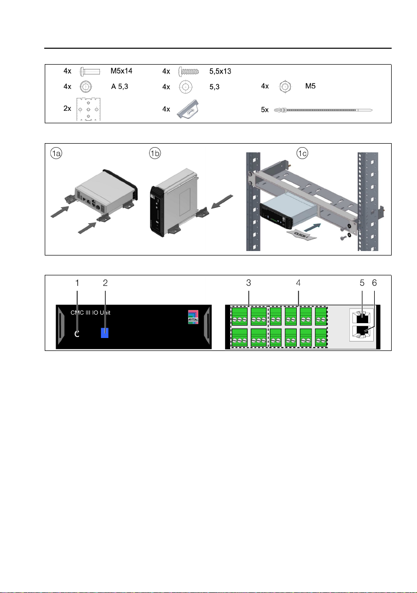
Abb./Fig./Fig. 1: Beigelegtes Zubehör / Provided accessories / Accessoires joints
Abb./Fig./Fig. 2: Montage / Assembly / Montage
Abb./Fig./Fig. 3: Bedienfeld, Stecker und Anschlüsse / Operator panel, plugs and connectors / Panneau de
commande, fiches et raccordements
Abbildungen /
Figures / Figures
Abbildungen / Figures / Figures

Rittal CMC III I/O Unit 3
DE
1 Hinweise zur Dokumentation
Diese Installations- und Kurz-Bedienungsanleitung richtet sich an versiertes Fachpersonal und enthält
nur die wichtigsten Informationen zur Montage, Installation und Funktion der CMC III I/O Unit (nachfol-
gend I/O Unit genannt).
1.1 Mitgeltende Unterlagen
Montage-, Installations- und Bedienungsanleitung CMC III I/O Unit.
Sie ist unter www.rittal.de verfügbar und enthält die vollständigen anwendungsrelevanten Informationen
und technischen Daten zur I/O Unit in Hinblick auf:
– Weitere Montagemöglichkeiten
– Details zum elektrischen Anschluss
– Funktionen und Services
– Konfigurationsmöglichkeiten
– Detaillierte Bedienungsanweisungen
– Fehlerbehebung
2 Sicherheitshinweise
– Montage und Installation des Geräts dürfen nur durch versiertes Fachpersonal erfolgen.
– Das Gehäuse der I/O Unit darf nicht geöffnet werden.
– Die I/O Unit darf nicht in Kontakt mit Wasser, aggressiven oder entzündbaren Gasen und Dämpfen
kommen.
– Die I/O Unit darf nur innerhalb der spezifizierten Umgebungsbedingungen betrieben werden (vgl.
Abschnitt 3.4).
3 Produktbeschreibung
3.1 Funktionsbeschreibung
Mit der I/O Unit können Signale von externen Systemen erfasst und im CMC III-System weiterverarbei-
tet werden. Des Weiteren können Steuerbefehle ausgeführt bzw. Meldungen an externe Systeme wei-
tergegeben werden. Hierzu stehen an der I/O Unit 8 digitale Eingänge und 4 Relais-Ausgänge zur Ver-
fügung. Die I/O Unit initialisiert sich automatisch nach dem Anschließen an das CAN-Bus-System.
3.2 Bestimmungsgemäße Verwendung
Die I/O Unit dient ausschließlich zum Einbinden externer Systeme über die digitalen Eingänge bzw. die
Relais-Ausgänge in das CMC III-System. Eine andere Verwendung ist nicht bestimmungsgemäß.
3.3 Lieferumfang
–CMCIIII/OUnit
– Beigelegtes Zubehör (Abb. 1)
– Installations- und Kurz-Bedienungsanleitung
3.4 Betriebsbedingungen
Die I/O Unit darf nur unter folgenden Betriebsbedingungen betrieben werden:
Temperatur-Einsatzbereich: +0°C bis +55°C
Feuchtigkeits-Einsatzbereich: 5% bis 95% relative Feuchte, nicht kondensierend
Schutzart: IP 30 nach IEC 60 529
Hinweise zur Dokumentation, Sicherheitshinweise, Produktbeschreibung
DE
DE
4Rittal CMC III I/O Unit
4 Montage
4.1 Montageanweisung
Die Montage der I/O Unit erfolgt gemäß Abb. 2.
5 Installation und Bedienung
5.1 Bedien- und Anzeigeelemente
Die Bedien- und Anzeigeelemente sind in Abb. 3 dargestellt.
Legende zu Abb. 3
1 „C“-Taste zur Quittierung von Meldungen
2 Multi-LED zur Statusanzeige
3 Relaisausgang (potenzialfreier Kontakt, max. 24 V ,1 A) (4 Stück)
4 Digitale Eingänge (für potenzialfreie Kontakte) (8 Stück)
5 CAN-Bus-Anschluss, 24 V
6 CAN-Bus-Anschluss, 24 V
5.2 Installation
Schließen Sie an den potenzialfreien Relaisausgängen die zu schaltenden Geräte an (Abb. 3, Pos. 3).
Beachten Sie hierbei die Pin-Belegung:
Speisen Sie an den digitalen Eingängen ein entsprechendes Signal ein (Abb. 3, Pos. 4).
Konfigurieren Sie über die Website der CMC III PU, ob am jeweiligen Anschluss ein Öffner („normally
closed“) oder ein Schließer („normally open“) angeschlossen ist (vgl. Abschnitt 5.3).
Verbinden Sie die I/O Unit über ein CAN-Bus-Verbindungskabel mit der CMC III PU bzw. den be-
nachbarten Elementen im CAN-Bus (Abb. 3, Pos. 9, 10).
Anzeige der Statusänderung:
– Die beiden grünen sowie die beiden roten CAN-Bus LEDs am CAN-Bus-Anschluss blinken.
– Die Multi-LED der Processing Unit blinkt dauerhaft in der Reihenfolge grün – orange – rot.
– Die Multi-LED der I/O Unit blinkt dauerhaft blau.
Drücken Sie die „C“-Taste an der CMC III PU (ein erster Signalton ertönt) und halten Sie sie für ca.
3 Sekunden gedrückt, bis ein zweiter Signalton ertönt.
Anzeige der Statusänderung an den CAN-Bus LEDs:
– Dauerlicht grüne LEDs: Status CAN-Bus „OK“.
– Dauerlicht rote LEDs: Status CAN-Bus fehlerhaft.
Anzeige der Statusänderung an der Multi-LED der Processing Unit:
– Grünes Dauerlicht: Alle am CAN-Bus angeschlossenen Geräte haben den Status „OK“.
– Oranges Dauerlicht: Mindestens ein am CAN-Bus angeschlossenes Gerät hat den Status „War-
nung“.
– Rotes Dauerlicht: Mindestens ein am CAN-Bus angeschlossenes Gerät hat den Status „Alarm“.
Hinweis:
Die Spannungsquellen an Pos. 3, 4, 5 sowie 6 (Abb. 3) müssen den Limited Power Sour-
ce (LPS)-Anforderungen nach UL 60950 genügen und die o.g. Grenzwerte einhalten.
Pin Signal
Pin 1 NC
Pin 2 NO
Pin 3 C
Montage, Installation und Bedienung

Rittal CMC III I/O Unit 5
DE
Anzeige der Statusänderung an der Multi-LED der I/O Unit:
– Dauerhaft blaues Blinken: Kommunikation über den CAN-Bus.
– Grünes Blinken: bei Messwertänderung oder spätestens alle 5 Sekunden.
Bei nicht erfolgreicher Installation: vgl. Abschnitt 1.1.
5.3 Einstellungen
Über die Website der CMC III PU können folgende Parameter eingestellt bzw. eingesehen werden:
Relaisausgang:
– Value: Aktueller Wert des Ausgangs (0 oder 1)
– Delay: Verzögerung der Statusmeldung [s]
– Status: Aktueller Status des jeweiligen Ausgangs unter Berücksichtigung des Delay-Wertes
Digitaler Eingang:
– Value: Aktueller Wert des Eingangs (0 oder 1)
– Logic: Auswahl „normally open“ (0) bzw. „normally closed“ (1)
– Delay: Verzögerung der Statusmeldung [s]
– Status: Aktueller Status des jeweiligen Eingangs unter Berücksichtigung des Delay-Wertes
Eventuell notwendige Softwareupdates: siehe www.rittal.de oder Anfrage bei Rittal Service (vgl.
Abschnitt 6).
6 Service
Zu technischen Fragen wenden Sie sich bitte an:
Tel.: +49(0)2772 505-9052
E-Mail: [email protected]
Homepage: www.rittal.de
Bei Reklamationen oder Servicebedarf wenden Sie sich bitte an:
Tel.: +49(0)2772 505-1855
E-Mail: [email protected]
Hinweis:
Verbindungskabel in verschiedenen Längen können über Fa. Rittal bezogen werden.
Installation und Bedienung, Service

EN
6Rittal CMC III I/O Unit
1 Notes on documentation
This installation and short user's guide is intended for experienced trained specialists and contains only
the most important information concerning the assembly, installation and function of the CMC III I/
O Unit (subsequently called I/O unit).
1.1 Associated documents
CMC III I/O Unit assembly, installation and user's guide.
It is available at www.rittal.com and contains the complete application-relevant information and techni-
cal data for the I/O unit with regard to:
– Further assembly possibilities
– Details concerning the electrical connection
– Functions and services
– Configuration possibilities
– Detailed operating instructions
– Troubleshooting
2 Safety instructions
– Assembly and installation of the device may only be performed by experienced trained specialists.
– The I/O unit housing must not be opened.
– The I/O unit may not come in contact with water, aggressive or inflammable gases and vapours.
– The I/O unit may only be operated within the specified environmental conditions (see section 3.4).
3 Product description
3.1 Functional description
The I/O unit can be used to acquire signals from external systems and to be further processed in the
CMC III system. In addition, control commands can be executed and messages forwarded to external
systems. For this purposes, the I/O unit provides eight digital inputs and four relay outputs. The I/O unit
initialises itself automatically after connection to the CAN bus system.
3.2 Proper use
The I/O unit is used exclusively for the connection of external systems using the digital inputs and the
relay outputs in the CMC III system. Any other use is not permitted.
3.3 Scope of delivery
– CMC III I/O Unit
– Provided accessories (fig. 1)
– Installation and Short User's Guide
3.4 Operating conditions
The I/O unit may only be operated under the following operating conditions:
Temperature operational range: +0°C to +55°C
Humidity operational range: 5% to 95% relative humidity, non-condensing
Degree of protection: IP 30 in accordance with IEC 60 529
Notes on documentation, Safety instructions, Product description
EN

Rittal CMC III I/O Unit 7
EN
4 Assembly
4.1 Assembly instructions
The assembly of the I/O unit is made as shown in fig. 2.
5 Installation and operation
5.1 Operating and display elements
The operating and display elements are shown in fig. 3.
Key for fig. 3
1 "C" key to acknowledge messages
2 Multi-LED for the status display
3 Alarm relay output (floating contact, max. 24 V , 1 A) (four)
4 Digital inputs (for floating contacts) (eight)
5 CAN bus connection, 24 V
6 CAN bus connection, 24 V
5.2 Installation
Close the switching devices to the voltage-free relay outputs (fig. 3, item 3).
Observe the pin assignment:
Feed an appropriate signal to the digital outputs (fig. 3, item 4).
Configure at the CMC III PU web site whether a normally closed contact or a normally open contact
is connected at the associated connection (see section 5.3).
Connect the I/O unit with a CAN bus connection cable to the CMC III PU or to the neighbouring el-
ements on the CAN bus (fig. 3, item 9, 10).
Display of the status change:
– The two green and the two red CAN bus LEDs on the CAN bus connection flash.
– The multi-LED of the Processing Unit flashes continually in the green – orange – red sequence.
– The multi-LED of the I/O unit flashes blue continuously.
Press the "C" key on the CMC III PU (a first audio signal is issued) and keep it pressed for approx.
3 seconds until a second audio signal is issued.
Display of the status change on the CAN bus LEDs:
– Green LEDs light continuously: CAN bus status "OK".
– Red LEDs light continuously: CAN bus status faulty.
Display of the status change on the multi-LED of the Processing Unit.
– Continuous green light: All units attached to the CAN bus have the "OK" status.
– Continuous orange light: At least one unit attached to the CAN bus has the "warning" status.
– Continuous red light: At least one unit attached to the CAN bus has the "alarm" status.
Note:
The voltage sources at positions 3, 4, 5 and 6 (fig. 3) must satisfy the Limited Power
Source (LPS) requirements in accordance with UL 60950 and observe the limit values
mentioned above.
Pin Signal
Pin 1 NC
Pin 2 NO
Pin 3 C
Assembly, Installation and operation

EN
8Rittal CMC III I/O Unit
Display of the status change on the multi-LED of the I/O unit:
– Continuous blue flashing: Communication over the CAN bus.
– Green flashing: When the measured value changes or, at the latest, every 5 seconds.
If the installation is not successful: see section 1.1.
5.3 Settings
The following parameters can be set or viewed at the CMC III PU web site:
Relay output:
– Value: Current value of the output (0 or 1)
– Delay: Status message delay [s]
– Status: Current status of the associated output taking account of the delay value
Digital input:
– Value: Current value of the input (0 or 1)
– Logic: "Normally open" (0) or "normally closed" (1) selection
– Delay: Status message delay [s]
– Status: Current status of the associated input taking account of the delay value
To determine whether any software updates are required: see www.rittal.com or contact Rittal Service
(see section 6).
6 Service
For technical questions, please contact:
Tel.: +49(0)2772 505-9052
E-mail: [email protected]
Homepage: www.rittal.com
For complaints or service requests, please contact:
Tel.: +49(0)2772 505-1855
E-mail: [email protected]
Note:
Connection cables in various lengths can be obtained from Rittal.
Installation and operation, Service

Unité E/S CMC III Rittal 9
FR
1 Remarques relatives à la documentation
Cette notice d'installation et d'utilisation succincte s'adresse à du personnel qualifié et chevronné et
contient uniquement les informations essentielles pour le montage, l'installation et le fonctionnement de
l'unité d'Entrées / Sorties CMC III (nommée unité E/S par la suite).
1.1 Autres documents applicables
Notice de montage, d'installation et d'utilisation de l'unité E/S CMC III.
Elle est disponible sur le site www.rittal.fr et contient les informations complètes relatives à la mise en
œuvre et les caractéristiques techniques de l'unité E/S dans les domaines suivants :
– Autres possibilités de montage
– Détails des raccordements électriques
– Fonctionnement et services
– Possibilités de configuration
– Instructions d'utilisation détaillées
– Suppression des défauts
2 Consignes de sécurité
– Le montage et l'installation de l'appareil doivent être réalisés uniquement par du personnel qualifié et
chevronné.
– Le boîtier de l'unité E/S ne doit pas être ouvert.
– L'unité E/S ne doit pas se trouver au contact de l'eau, de gaz et de vapeurs agressifs ou inflam-
mables.
– L'unité E/S doit être mise en œuvre uniquement dans les conditions ambiantes spécifiées (voir
paragraphe 3.4).
3 Description du produit
3.1 Principe de fonctionnement
L'unité E/S permet l'acquisition des signaux des systèmes externes et leur traitement immédiat dans le
système CMC III. De plus, des instructions de commande peuvent être exécutées et les messages
transmis aux systèmes externes. Pour cela, l'unitéE/Sdisposentde8entrées numériques et de
4 sorties relais. L'unité E/S s'initialise automatiquement après le raccordement au système CAN-Bus.
3.2 Utilisation conforme au règlement
L'unité E/S sert uniquement à intégrer des systèmes externes via les entrées numériques ou les sorties
relais dans le système CMC III. Toute autre utilisation est non conforme.
3.3 Composition de la livraison
– Unité E/S CMC III
– Accessoires joints (fig. 1)
– Notice d'installation et d'utilisation succincte
3.4 Conditions de fonctionnement
L'unité E/S doit être mise en œuvre uniquement dans les conditions de fonctionnement suivantes :
Plage de température tolérée : +0°C à +55°C
Plage d'humidité tolérée : 5% à 95% d'humidité relative, sans condensation
Indice de protection : IP 30 selon CEI 60 529
Remarques relatives à la documentation, Consignes de sécurité, Description du produit
FR
FR
10 Unité E/S CMC III Rittal
4 Montage
4.1 Instruction de montage
Le montage de l'unité E/S se réalise conformément à la fig. 2.
5 Installation et utilisation
5.1 Organes de commande et de signalisation
Les organes de commande et de signalisation sont présentés sur la fig. 3.
Légende pour la fig. 3
1 Touche «C» pour l'acquittement des messages
2 LED multiple pour l'affichage d'état
3 Sortie relais (contact sec, max. 24 V ,1 A) (4 pièces)
4 Entrées numériques (pour les contacts sec) (8 unités)
5 Raccordement CAN-Bus, 24 V
6 Raccordement CAN-Bus, 24 V
5.2 Installation
Raccorder les appareils aux sorties relais sans potentiel (fig. 3, pos. 3).
Tenir compte ici de l'affectation des bornes :
Introduire un signal correspondant aux entrées numériques (fig. 3, pos. 4).
Configurer sur l'interface WEB de l'UC CMC III si un rupteur («normally closed») ou un contacteur
(«normally open») est connecté à la borne respective (voir paragraphe 5.3).
Connecter l'unité E/S à l'UC CMC III ou aux éléments voisins du CAN-Bus via un câble de raccorde-
ment CAN-Bus (fig. 3, pos. 9, 10).
Affichage de la modification d'état :
– Les deux LED vertes ainsi que les deux LED rouges du raccordement CAN-Bus clignotent.
– La LED multiple de l'unité centrale clignote de manière continue dans l'ordre vert – orange – rouge.
– La LED multiple de l'unité E/S clignote en bleu de manière continue.
Actionner la touche «C» de l'UC CMC III (un premier signal sonore retentit) et la maintenir actionnée
pendant env. 3 secondes jusqu'à ce qu'un deuxième signal sonore retentisse.
Affichage de la modification d'état sur la LED du CAN-Bus :
– La LED verte est allumée en continue : état du CAN-Bus «OK».
– La LED rouge est allumée en continue : état défectueux du CAN-Bus.
Affichage de la modification d'état sur la LED multiple de l'unité centrale :
– Lumière verte continue : tous les appareils raccordés au CAN-Bus sont dans l'état «OK».
– Lumière orange continue : au moins un appareil raccordé au CAN-Bus est dans l'état «Avertisse-
ment».
– Lumière rouge continue : au moins un appareil raccordé au CAN-Bus est dans l'état «Alarme».
Remarque :
Les sources d'alimentation aux bornes 3, 4, 5 et 6 (fig. 3) doivent satisfaire aux exigences
des 'sources à puissance limitée' (LPS) conformément à la Norme UL 60950 et respecter
les valeurs limites spécifiées plus haut.
Borne Signal
Borne 1 NC
Borne 2 NO
Borne 3 C
Montage, Installation et utilisation

Unité E/S CMC III Rittal 11
FR
Affichage de la modification d'état sur la LED multiple de l'unité E/S :
– Clignotement bleu continu : communication via le CAN-Bus.
– Clignotement vert : lors d'une modification de la valeur de mesure ou au plus tard toutes les
5 secondes.
En cas d'échec de l'installation : voir paragraphe 1.1.
5.3 Réglages
Les paramètres suivants peuvent être réglés ou consultés sur l'interface WEB de l'UC CMC III :
Sortie relais :
– Value : valeur actuelle de la sortie (0 ou 1)
– Delay : temporisation du message d'état [s]
– Status : état actuel de la sortie respective en tenant compte de la valeur Delay
Entrée numérique :
– Value : valeur actuelle de l'entrée (0 ou 1)
– Logic : Sélection «normally open» (0) ou «normally closed» (1)
– Delay : temporisation du message d'état [s]
– Status : état actuel de l'entrée respective en tenant compte de la valeur Delay
Si des mises à jour logicielles sont éventuellement nécessaires : voir www.rittal.com ou sur demande
au service Rittal (voir paragraphe 6).
6 Service
Pour des questions techniques, veuillez vous adresser à :
Tél. : +49(0)2772 505-9052
Site Internet : www.rittal.com
Pour des réclamations ou un service, veuillez vous adresser à :
Tél. : +49(0)2772 505-1855
Remarque :
Les câbles de raccordement de différentes longueurs peuvent être commandés auprès
de la société Rittal.
Installation et utilisation, Service
◾Enclosures
◾ Power Distribution
◾ClimateControl
◾ITInfrastructure
◾ Software & Services
You can find the contact details of all
Rittal companies throughout the world here.
www.rittal.com/contact
08.2016 / ID no. D-0000-00000528 Rev00
Other manuals for CMC III
9
This manual suits for next models
1
Table of contents
Languages:
Other Rittal Measuring Instrument manuals


Popular Measuring Instrument manuals by other brands


REED
REED r8001 instruction manual

Bosch
Bosch GTL 3 Professional Original instructions

Precision Digital Corporation
Precision Digital Corporation PD6801-0K1-M20 instruction manual

CID Bio-Science
CID Bio-Science CI-600 instruction manual

Reichert
Reichert AR700 user guide

Gobius
Gobius Pro Instructions on Paper


