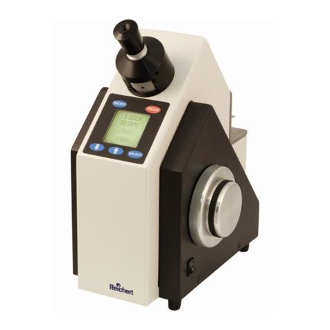
Reichert AR700 User manual

1
AR7
SERIES
Automatic Refractometer
User’s Guide

2

3
Table of Contents
Preliminary Information Table of Contents 3
Warnings and Cautions 4
Introduction Congratulations on your Purchase 5
Environmental Conditions 6
Electrical Ratings/Specifications 6
Instrument Features 7
Instrument Initialization Set Up 8
Operation Set Point Calibration 9
Multi Point Calibration 10
Sample Reading 12
Shadow line display 12
Operational Parameters / Sample Temperature Effects on Readings 13
Features Automatic Temperature Compensation 14
Temperature coefficient and correction calculations 14
Display Screen/Explanation of Functions 16
Printer Output 18
RS232 Serial Port 18
Serial Control Codes 18
Channel 1 – ICUMSA Brix 19
Channels 2 – 15, User Programmable 19
Key Pad Function, Lock/Unlock 19
Error Messages 20
Maintenance / Specifications Care and Cleaning 21
Care of Prism Surface 21
Preventative Maintenace 21
Accessories Extended Precision Calibration Oils 22
Flow Cell 22
Funnel Cell 22
Sample Press 22
Warranty Warranty Terms 23

4
Symbol Information
Thefollowingsymbolsappearontheinstrument:
CAUTION: Risk of electric shock
CAUTION: Replace with same type and rating fuse 5x20, 3.15A,
250V Quick Acting.
CAUTION: Indicatesthatimportantoperatingandmaintenance
are included in this User’s Guide.
Warnings and Cautions
CAUTION:INORDERTOINSURETHATCORRECTOPERATIONOFTHEAR7SERIES
INSTRUMENTIS MAINTAINED,ANYREPAIRORSERVICE MUSTBE PERFORMED BY
EXPERIENCEDPERSONNELTHATARETRAINED BYREICHERTINC.
CAUTION ESDS: THEINTERNALCIRCUITRYOFTHEAR7SERIESCONTAINSELEC-
TROSTATICDISCHARGESENSITIVE DEVICES (ESDS).SUCHCOMPONENTS MAYBE
SENSITIVETOHIGHVOLTAGESPRODUCEDBYSTATICDISCHARGES.
CAUTION: DONOTUSE STRONGSOLVENTSORSTRONG CLEANINGSOLUTIONS
ONANYPARTOFTHEAR7 SERIES OR DAMAGE TO THE UNITMAYOCCUR.
WARNING: DO NOTREMOVEORDEFEATTHEEARTHGROUNDCONNECTIONON
THE AR7SERIESPOWERINPUTCONNECTORORTHEUNIT’SPOWERCORD.
DAMAGETOTHEAR7 SERIES INSTRUMENTAND/OR INJURYTOTHEOPERATOR
MAYOCCUR.
WARNING: THEAR7 SERIES SHOULD BEUSEDINSTRICTACCORDANCEWITHTHE
INSTRUCTIONSOUTLINED INTHISUSER’SGUIDE.THESAFETYOFTHEOPERATOR
ANDTHE PERFORMANCE OFTHEINSTRUMENTCANNOT BEGUARANTEEDIF
USEDINAMANNERNOTSPECIFIEDBYREICHERTINC.

5
INTRODUCTION
Congratulations on your purchase of your new ReichertAR7 SERIES Refractometer.
This manual describes the proper operation and care of this state of the art instrument.
TheAR7 SERIES is an automatic, bench top refractometer with digital read out and is
capableof measuring % Solids (Brix), % Solids-TC (Brix-TemperatureCompensated,
Sucrose),RefractiveIndex and Refractive Index-TC. The Peltiercontrollereliminatesthe
needfor a water bath and has the greatest controllable temperature range set point
available.
AnAR7 SERIES has the capability to display data in four languages, English, Spanish,
Frenchand German and can measure refractive index of liquid solutions toa precisionof
0.00005 or % solids (Brix) to 0.03. While the instrument has many capabilities it’s
functionality can be expanded considerably by a simple connection to a PC.
Please note that a Refractometer is a high precision optical instrument. It is absolutely
necessary to properly maintain the instrument to obtain the best possible accuracy. This
includes thoroughly cleaning the prism and well after each sample, routinely calibrating
the instrument.

6
ENVIROMENTAL CONDITIONS
•IndoorUseonly
•TemperatureRange 10oC–45oC
•Max. relative humidity – 80% for temperatures up 31oCdecreasinglinearly to
50%(relativehumidityat40oC)
•InstallationcategoryII (over voltagecategory)
•Pollutiondegree2
•Altitude up to 2,000 meters
ELECTRICAL RATINGS/SPECIFICATIONS
TheReichertAR7 SERIES incorporates an auto sensing, switchingAC power
supply.Neveruseanadapter, which will interrupt the protective grounding.
•Caution: Risk of electrical shock exists if the cover of the
AR7SERIESisremoved.Hazardousvoltageswillbe
exposed, which can cause injury or death. Refer
servicingtoaqualifiedservicetechnician.
•SupplyVoltage: 90 to 264VAC,47-63HZ
Inputpower– 220W PMAX
•Fuses: 3.15A/250VAC, QuickActing
•Illumination: Long Life LED with 589nm bandpass filter.
•Range, Channel1: 0 to 100% Dissolved Solids, Sucrose per
ICUMSA.
1.32000to1.60000nDRefractiveindex(nD-SodiumD
linerefractive index).
•Readability: AR700: 0.01% Solids, 0.00001nD
AR70: 0.1% Solids, 0.0001nD
•Precision: AR700: +/- 0.01% Solids, +/-0.00001nD.
AR70: +/- 0.1% Solids, +/-0.0001nD.
•Accuracy: AR700: +/- 0.03% Solids, +/-0.00005nD.
AR70: +/- 0.1% Solids, +/-0.0001nD.
Typical clear samples, % Solids Temperature
Compensated,asSucrose.
•TemperatureCompensation Range:
Channel1: 10 to 45oC per ICUMSA tables.
Channels 2-15:userdefinable.
•Prism Assembly: Synthetic Sapphire mechanically sealed to
Stainless Steel Well with Teflon Gasket.
•Dimensions: 13”W x 16”L x 4 .5” H Weight: 17lbs
(33cm x 40.6cm x 11.5cm) (7.7kg)

7
INSTRUMENT FEATURES
1. Instrument Display –Digitallydisplaysmeasurementvalues,operator
instructionsand error messages.
2. Keypad Controls –All five controls are soft touch membrane keys,
FUNCTION/down,SETUP/up,CALIBRATE/left,MODE/right, and READ. These
keys, other than the Read key , serve a dual purpose as function keys and also
facilitatemovingthe displayed curser/highlighter when selecting the many
availableoptionsthroughthe“SETUP”screen.
3. Sample Well Cover – The hinged, sample well cover is used
to eliminate or minimize stray light when taking sample readings. It also reduces
theeffects of evaporation. Keeping the cover closed when the instrument isnot in
use will prevent possible damage and contamination to the sample well and prism
surface.Thesamplewell cover is made of Delrin.
4. Sample Well – The sample well is made of 416 grade Stainless Steel with a
Sapphire Prism mounted to its center. When a sample is placed on the Sapphire
Prism face, it is important that the sample cover the entire prism surface to attain
an accurate reading. Avoid any air bubbles or particulate matter from settling on
theprism to reduce reading variability.
CALIBRATE
FUNCTION
SET UP
MODE
READ
Reichert
Automatic Refractometer AR700
Main Ver. 2.01
LSA Ver. 1.57
CPLD Ver. 0005
To calibrate press CALIBRATE
or for set up press SETUP
09:05 Well Temp
20.02

8
SET UP
A. Unpack instrument from carton. Retain packing material for future
storage/protection/shipping.
B. Place the instrument indoors on a solid surface in an environment where the
temperature is stable. Be sure to keep instrument away from air conditioning
vents or water bath exhaust, drafts can affect the temperature stability.
C. Plug the mating end of the Power Cord into the receptacle located on
the back of the instrument. Plug the opposite end of the Power Cord into an
apropriatereceptacleto supply the instrument withpower.Neveruseanadapter,
whichwillinterruptthe protective grounding. Supply Voltage:90 to 264VAC,47-63
HZInputpower – 220WPMAX
DB9Connectors Receptacle
Power Switch Air Intake
D. Turn the instrument on by activating the power switch located on the
rearpanel.
E. Set at the desired operating temperature in the set up screen by pressing SET
UPand scrolling toTemperatureSetpoint.
F. Allow the instrument a warm up period of at least 30 minutes before calibration
orsamplereading.
AR700 Setup
Calibration Auto Temperature Channel/
Routine Equilibration Scale
----------------------------------------
Set & Span Off (ICUMSA)
Temperature Contrast Advanced Exit
Setpoint Options
----------------------------------------
20.00 C U/D U U
L/R to choose option
U/D to change setting
To exit press READ
SET POINT CALIBRATION( Calibration with distilled water only, also
referred to single point calibration )
A. Turn the instrument on by activating the power switch located on the
rearpanel.
B. Set at the desired operating temperature in the set up screen by pressing SET
UPand scrolling toTemperatureSetpoint.
C. Allow the instrument a warm up period of at least 30 minutes before calibration.
D. Press “CALIBRATE”.

9
Water calibration complete
1.33299 INDEX-TC
Reference Temperature 20 C
Press SETUP to continue
1.33299 INDEX-TC
20.00 C
3:28 PM
3:32 PM Well Temp
Channel 1 Sucrose (ICUMSA) 24.99 C
Reading and Calibrating
. . .
Clean prism and press
CALIBRATE again to
re
initiate
or any other key to cancel
Well Temp
20.01 C
Use MODE to select mode
Current mode
INDEX-TC
Add distilled water to sample well.
Allow to equilibrate then
press CALIBRATE.
Well temp.
20.01C
E. Follow the displayed instructions to clean prism and press
“CALIBRATE” again.
F. Selectreading mode by pressing “MODE”, Index-TC, Solids-TC.
G. Apply enough distilled water to cover the the prism surface, allow to
temperature equilibrate and press “CALIBRATE”.
H. Water calibration complete. Reported value should be 1.33299 +/-
.00005.
I. Press “SET UP” to continue. You are now in the reading screen.
J. Note, it is recommended to clean the air intake on the back of the
instrument and exhaust located on the bottom and perform the single
point distilled water calibration daily, outlined above.

10
SET & SPAN CALIBRATION (Also known as Multi-point Calibration )
TheAR7 SERIES can be calibrated with up to 5 points using 4 standards and
distilledwater. Performing a 2 point calibration will provide the requiredaccuracy
neededusingdistilledwaterandthesuppliedhighrefractiveindexcertified
standard. The reason for the 3, 4 and 5, point calibrations is to precisely calibrate
theinstrumenttocertifiedstandardsneartherefractiveindexrangewherethe
measurements are being made. It is extremely important to note that when
performingthe multipoint calibration that the lowest valued standard be used first,
proceedingupwardtothehighestvaluedstandard, the standards should not be
appliedrandomly. Please see the procedure below to perform the multipoint
calibration.
A. Raise the sample well cover and inspect the prism and well for
cleanliness.Clean with soapy water, methanolor
Isopropyl alcohol as required, followed by distilled water then dry the prism and
well.
B. Press the “SET UP” key on the touch panel, the “Set Up” screen will appear.
C. Highlight“Calibration Routine” usingLeft (calibrate), Right (mode), Up (read),
Down(function)keys.
D. Change the default setting to “Set & Span” using the Up/Down keys.
E. Press the “READ” key to exit this screen.
F. Press the “CALIBRATE” key to continue. Follow the displayed instructions to
cleanprismandpress“CALIBRATE” again.
G. Follow the on screen instructions to add Distilled Water, allow to temperature
equilibrate and press “CALIBRATE”.Watercalibration complete 1.33299, press
“SET UP” to continue.
AR700 Setup
Calibration Auto Temperature Channel/
Routine Equilibration Scale
----------------------------------------
Set & Span Off (ICUMSA)
Temperature Contrast Advanced Exit
Setpoint Options
----------------------------------------
20.00 C U/D U U
L/R to choose option
U/D to change setting
To exit press READ
Clean prism and press
CALIBRATE again to
re
initiate
or any other key to cancel
Well Temp
20.01 C
Initiating - Please wait
Multipoint Calibration
Use MODE to select mode
current mode
Index-TC
Add distilled water to sample well.
Allow to equilibrate then
press CALIBRATE
Well temp.
20.01C
Water calibration complete
1.33299 INDEX-TC
Reference Temperature 20 C
Press SETUP to continue

11
SPAN CALIBRATION
Highlight point, select with READ
Repeat with additional points as needed
When complete, select EXIT
Refractive Brix Last
Index Equivalent Calibrated
1.40229 41.24 _ _ _ _ _ _
1.45755 67.72 _ _ _ _ _ _
1.51416 88.73 _ _ _ _ _ _
1.57230 N/H _ _ _ _ _ _
EXIT
Use U/D to highlight, READ to select
Calibration point complete
1.51416 INDEX
Reference Temperature 25 C
Press SETUP to continue
H. Select the next point using the up/dwn keys to highlight the desired point, for
example: 1.51416. Press “READ” to accept. Note that calibration must be in
ascendingorderofrefractive index value. If the calibration standard hasavalue
other than listed, move the curser to the value that is inbetween two values that
bracketthestandardsvalue. For example, if the standard value is 1.52146, move
curserto 1.51416 since 1.52146 is higher than 1.45755 and lower than 1.57230.
Proceed to step I.
I. Adjusttherefractive index value which should now be displayed, to the value
listed on the bottle of calibration fluid by pressing “SET UP”. Use the up/dwn/left/
right keys to adjust value. When the value matches press “READ” to accept and
continue.Adjust temperaturecoefficient valueor press “READ” tocontinue.
Change reference temperatureor press “READ”to continue. If the displayed
value matches the value as listed on the bottle of calibration oil, press
“CALIBRATE” to continue.
J. Add the stated Calibration Standard (ex: 1.51416) to cover prism, allow to
temperatureequilibrateand press“CALIBRATE” to continue.
K. Calibration point complete, press “SET UP” to continue.
L. Highlight another calibration point or EXIT and press “READ” to select.
Calibration Standard
Index
1.51416
Press SETUP to edit
Press CALIBRATE to continue
SPAN CALIBRATION
Highlight point, select with READ
Repeat with additional points as needed
When complete, select EXIT
Refractive Brix Last
Index Equivalent Calibrated
1.40229 41.24 _ _ _ _ _ _
1.45755 67.72 _ _ _ _ _ _
1.51416 88.73 _ _ _ _ _ _
1.57230 N/H _ _ _ _ _ _
EXIT
Use U/D to highlight, READ to select

12
SAMPLE READING
A. Clean and dry the prism and well.
B. Addsampleandallowtotemperatureequilibrate.
C. Press“READ”.
D. Notevalueondisplay.
E. Use“MODE” key toswitch betweenthe four modesof measurement:
1. INDEX=Refractive index.
2. INDEX-TC=Refractive Index,TemperatureCompensated.
3. SOLIDS = Percent Concentration.
4. SOLIDS-TC=Percent Concentration,Temperature Compensated.
The above modes in channel one are for measurement of Sucrose or “Brix”
scale per the International Commission for Uniform Methods. All other channels
are custom scales.
F. Compare reading to known value. Note any difference in well temperature from
samplereferencetemperatureandadjust refractive index reading mathematically
from the “INDEX”displayed value.
Graphic Representation of Detector as Seen on Display
0
50000
100000
150000
200000
250000
1
150
299
448
597
746
895
1044
1193
1342
1491
1640
1789
1938
2087
2236
2385
2534
2683
2832
2981
3130
3279
3428
3577
Pixel Number of Detector
Voltage output of Detector
SHADOW LINE DISPLAY
TheAR7 SERIES has the ability to graphically display the shadow line enabling
the user to see what the instrument sees. To operate this feature after taking a
reading press and hold the “FUNCTION” key for at least five seconds. When the
key is then released theAR7 SERIES will generate and display a graph of the
Linear ScannedArray output. To exit the shadow line display press “READ”.

13
SAMPLE TEMPERATURE EFFECTS ON READINGS
Refractive Index is a physical property of a material. It changes with concentration
and with temperature.As a result, samples need to be at a stable temperature
whenreadandthereadingwill be different depending on the sample temperature.
This phenomenon is true for Brix or any other unit of measure that a refractometer
canbe programmed to report in since these are calculated from refractive index.
ThecommonmethodsofmanagingthisareAutomatic Temperature
Compensation(ATC)andcontrolofthesample/prismtemperature.
AutomaticTemperature Compensation
AutomaticTemperatureCompensation (ATC). Since most uses of refractive index
is in controlling concentration, it is useful to eliminate the temperature effects
whenlooking at instrument readings. One standard method is to have
programmed channels that calculate the correct reading at 20C for a sample that
isbeing read at other temperatures. This allows comparing readings to formula or
processspecificationusing20Cvalueswithoutdoingcomplicatedconversions.
Note that custom channels to do temperature compensation are specific to the
materialdevelopedforandmostlikelywillprovidepoorreadingsifusedfora
differentmaterial.
The automatic temperature compensation modes built into…

14
AUTOMATIC TEMPERATURE COMPENSATION
Automatictemperaturecompensationcorrectsreadingsover a range of
temperatures.As an example: Samples taken at 10oC – 40oC are corrected to a
referencetemperaturereading of 20oC.Temperaturecorrectionisnecessary
becauserefractiveindexvaries inversely with temperature, as temperatureof
samplerisesrefractiveindexfallsandassampletemperaturedropsrefractive
index will rise. The reason for this is that a sample whose temperature is
changingwillreportchangingrefractiveindexmeasurements.To speedgetting
sample temperature to stabilize, theAR7 SERIES has an internal peltier which
can be set to do this. it is necessary to allow the sample temperature to
equilibrate so that the instrument can properly read the sample.
The automatic temperature compensation modes built into theAR7 SERIESare
basedon the temperature coefficients (nD/oC) of sucrose, per the ICUMSA scales.
Whenreadings are takeninINDEX-TC (refractive index-temperaturecompensated)
mode the coefficients are only valid for sucrose solutions.Atypical temperature
coefficient for an aqueous solution is –0.0002/oC and for an organic solution it is
typically
–0.0004/oC. You can calculate the correct temperature coefficient for a specific
solutionusingthefollowingroutine.
Temperature Coefficient Calculations (non-Sucrose samples)
To calculate the temperature coefficient of a sample, the sample must be read in
theIndexMode.Take note of the reported value and thereadingtemperature.The
sample must then be read at a second temperature. The following calculation may
then be used.
TemperatureCoefficient=(nD1 –nD2)/(T1-T2)
where:
nD1=RefractiveIndexofsampleattemperature1
nD2=RefractiveIndexofsampleattemperature2
T1=Temperature ofRefractiveIndexreading 1
T2=Temperature ofRefractiveIndexreading 2
The temperature coefficientisalmostalwaysa negative number,in other words,
refractiveindexincreasesastemperaturedecreasesand thereforedecreasesas
temperaturerises.Typicaltemperature coefficientsfor fluids will be from –0.0001
to–0.0004. Once a temperature coefficient is known, the temperature corrected
refractiveindexcanbecalculated from an actual refractive index reading by the
followingformula:

15
RITC=((RT-AT)*TC)+RI
Where:
RITC= RefractiveIndexTemperatureCorrected
RT= ReferenceTemperature
AT =Actual Temperature as Read on Instrument
TC=Temperature CoefficientOf Sample
RI=Actual Refractive IndexAsReadOnRefractometer
Example:CalibrationVerificationof an instrument using a known fluid
1. Acertified calibration oil is read on an automatic refractometer as having
a refractive index of 1.51519 at 22.48°C.
2. The actual value of the oil as certified by N.I.S.T. is R.I. = 1.51416,
ReferenceTemperature = 25°C,
Temperature Coefficient = -0.000412 dn/dt.
3. Temperature Differential= ReferenceTemp. -ActualReading
Temperature = 25.00 - 22.48 = 2.52
4. Temperature Compensation Factor =TemperatureDifferentialtimes
Temperature Coefficient = (2.52) x (-0.000412) = -0.00103824
5. -0.00103824+ 1.51519 = 1.51415176. This would be the temperature
corrected refractive index at 25°C In this case, if the value obtained
above differs from the known value of the calibration standard by more
than the accuracy tolerance for the instrument, calibration of the
instrument is necessary.
Sample/prismTemperature Control
Whether usingATC or not, if the temperature of the sample is changing
whilereadingthereportedvaluewillbechangingaswell.This
phenomenon was used in the previous section in a controlled way to
calculatehow the refractive index of a specific material changes with
temperature. Another example is that calibration oils typically change
about .0004 refractive index units/C (look on the label for the specific
value).Controllingtemperature during calibrationsandwhen reading
samplesis important to accurate and reproducible readings.
To avoid the errors unstable sample temperature can cause, theAR700/
AR70 has an internal peltier which can be set for any temperature from
10C below room temperature to as high as 100C. This is useful when
working with samples that are not at room temperature as the
instrument can be set to measure at the temperature the samples come
intothe lab at allowing for temperature equilibrium to be established
quickly.

16
DISPLAY SCREEN/EXPLANATION OF FUNCTIONS
Press the “SET UP” key to access the AR7 SERIES Setup screen. Use the
“RIGHT/LEFT “keys to advance through the function choices. Use the “UP/
DOWN” keys to change the default settings.
A. CALIBRATION ROUTINE – Default “Set Pt”, which is a calibration using
distilled water only. “Set and Span” uses water and up to 4 user defined
standardsto more accurately target a refractive index range where most
readingswillbemade.
B. AUTO TEMPERATURE EQUILIBRATION –Default “OFF”.Autoequilibration
will automatically detect when the sample and prism have reached thermal
equilibrium. When this feature is activated a sample is applied and “READ”
has been pressed the instrument will monitor the temperature until it
stabilizes. The instrument will then automatically take the reading. During
the monitoring period a graph will be displayed of the dynamic well
temperaturevs.time.
C. CHANNEL–Default“ICUMSA”. Channel 1isprogrammedfor “BRIX” from
the InternationalCommissionfor Uniform Methods of SugarAnalysis
sucrose(ICUMSA) scale, temperature compensated in TC mode to 20 o C.
Channels2through15areuserprogrammablechannels.Fordirectionsand
an explanation of the necessity of custom channels please request
Technical Bulletin“CustomChannelGenerationforAutomatic Refractometer
Line”.Notifyyourrepresentative of the instruments software version,
displayedwhenfirstturned on as Ver. XX.X.
D. TEMPERATURE SETPOINT –Tocontrol the sample/prism temperature,
highlight this selection and use the UP/DWN keys to adjust.
E. CONTRAST - Once highlighted the display contrast can be adjusted by
pressing and holding the up or down key until the desired contrast is
attained.
F. ADVANCED OPTIONS –Selecting this optionrefreshes the displayand
offersanotherSetupscreenwithadditionaloptions.
AR700 Setup
Calibration Auto Temperature Channel/
Routine Equilibration Scale
----------------------------------------
Set Pt. Off (ICUMSA)
Temperature Contrast Advanced Exit
Setpoint Options
----------------------------------------
20.00 C U/D U U
L/R to choose option
U/D to change setting
To exit press READ
AR700 Setup
Baud Date Time
Rate
----------------------------------------
115200 Jan 6 2003 18:36
Password Language Primary Exit
Options
----------------------------------------
OFF English U U
L/R to choose option
U/D to change setting
To exit press READ
AR700 Setup
Interval Delay Calibration History
Timer Timer Display
----------------------------------------
Off Off U
Index Restore More Exit
Readability Defaults Options
----------------------------------------
0.00001 U U U
L/R to choose option
U/D to change setting
To exit press READ

17
G. INTERVAL TIMER – Default “OFF”. Set in HH:MM:SS format, this option
allowsthe instrument to take readings at definable intervals. Once activated
and defined theAR7 SERIES will continually take readings until a lock out
error occurs such as a lack of sample, or the option is disabled. Interval
Timer is set to “OFF” when the HH:MM:SS is set to 00:00:00 and it is
deselected.
H. DELAY TIMER – Default “0 SECONDS”. Sets the time a sample is read
once the “READ” or “CALIBRATE” keys are pressed. This parameter is set
in 15 second intervals up to 4 minutes.Acount down timer is displayed after
pressing the “READ” or “CALIBRATE” keys when this option is used.
I. CALIBRATION HISTORY – Pressing the “UP” keywilldisplaythe previous
512 calibration records. Some parameters extend beyond the limits of the
display, to view these press the Up/Dwn/Lft/Rt keys until the desired
parameterorrecordisvisible.
J. INDEX READABILITY – Pressing the “UP” or “DOWN” key will change
theindexreportedvaluefrom 0.00001 to 0.0001.
K. RESTORE DEFAULTS – Pressingthe “UP” key will activate another screen
with instructions to press “FUNCTION” to restore defaults or press “SET
UP” to cancel. This allows the user to restore all factory defaults. It will not
erase custom channels or calibration history.
L. More Options– Press the “SET UP” key to advance to further Set Up
options.
M. BAUD RATE – Default “115200 bps”. Baud rate options for the RS232 serial
portsare: 57600, 38400, 19200, 9600, 4800 and 2400bps.
N. DATE – Format is Month/Day/Year. Use the “Up/Dwn/Lft /Rt” keys to
navigateandchangethe date.
O. TIME – Can be set to standard 12 hour am/pm or 24 hour military time. Use
the “Up/Dwn/Lft /Rt” keys to navigate and change the time.
P. PASSWORD – Default “OFF”. Password protection can be used to secure
options once they are set. Turning this option “ON” and pressing “SET UP”
displays the “Enter Password” screen. Use the arrow keys to enter a 3 digit
numerical password. Press “SET UP” to exit.Asecond screen confirming
your password will appear. Press “READ” to accept the new password or
“SET UP” to cancel. Once the password has been entered theAR7 SERIES
will prompt the user for it each time the Set Up screen is accessed. Keeping
a record of the password in a secure location is recommended.
Q. LANGUAGE –Default “ ENGLISH”. Language can be changedtoSpanish,
French or Germanby pressing the “UP”or “DOWN” keys to advance through
the choices. Note that the custom channel names and definitions will appear
as entered in the custom channel program.
R. PRIMARY OPTIONS - Press the “UP” key to return to the initial AR7
SERIES Set Up screen.
S. EXIT - Pressing the “UP” key returns theAR7 SERIES to the normal
display.

18
RS232 SERIAL PORT
TheAR7 SERIES includes two serial communications ports, DB-9 position female
connectors, located on the instrument’s back panel. Communications settings are: 8
Data Bits, No Parity, 1 Stop Bit. Flow Control Xon/Xoff, Baud Rate settings described
in section 10.0 M, 19200 recommended. Connect to computer with a 9 pin serial
cable,DO NOT USE a “Null Modem Cable” when making the connection.IMPORTANT
NOTE:Connect any required accessories (printer,computer) to the appropriate COM
port on the instrument utilizing the included null modem cables. Do not disconnect
withoutturning off power to the instrument.
TheAR7 SERIES is capable of being controlled from a computer through the Serial
Port interface by using any standard communications program such as “Terminal” or
“Hyperterminal”.Readingoutputthroughtheserialport may be formatted to retrieve
virtually any data, in any order desired.To format the serial string output, type “help sf”,
brief instructions will appear. To set the serial format, type “sf” followed by the letters
for the output options desired.The default setting is GFA.
SERIAL CONTROL CODES
Many of the advanced functions can only be accessed and set
through the serial port connection. For a complete list of those
codescontactyour technical customer service representative.
PRINTER OUTPUT
Theprinteroutputisprovidedforconnectinganexternalprinterthrougheitheroftwo
DB–9 female connectors located on the instrument’s back panel. Communication is by
a 7 bit, parallel bus interface with synchronous operation.

19
CHANNEL 1 – ICUMSA BRIX
TheAR7 SERIES is preprogrammed at the factory with channel 1 to read % Sucrose
or “Brix” scale per the International Commission for Uniform Methods of SugarAnalysis
(ICUMSA).Temperature Corrected (TC) readings inchannel1arevalid for Sucrose
only!
CHANNEL 2 – 15, USER PROGRAMABLE
Userprogrammablechannelsor custom channels may be programmed using your own
Refractive index, Temperature, % Solids data.Access to the channels is from the Set
Up screen. Custom channels can include definitions for units of measure such as
specific gravity, % protein, g/ml, etc. The units of measure labels are completely
definable and up to 20 characters can be used.
To learn more about Custom channel programming,request“CustomChannel
GenerationforAutomaticRefractometer Line”. Be sure to inform the technical service
representativeof the software version in your instrument, which is displayed as Ver
XX.Xwhentheunitisfirstturned on.
FUNCTION, LOCK/UNLOCK
During the opening screen when the instrument is first turned on, the keypad can be
lockedandunlockedbypressingthe“READ”/“CALIBRATE” then“READ”/“MODE”
keys in that order.

20
ERROR MESSAGES
MESSAGE: Refractive index of sample exceeds AR7 SERIES limits.
CAUSE: Applied sample appears to have a refractive index greater than 1.60000
MESSAGE: Refractive index of sample is below AR7 SERIES limits.
CAUSE: Applied sample appears to have a refractive index lower than 1.32000
MESSAGE: Refractive index of sample exceeds channel limits.
CAUSE: Custom channel range does not include refractive index found.
MESSAGE: The index of your sample was higher than expected.
CAUSE: During calibration, the refractive index of an applied standard was found
to be higher than either the default or user edited index by 0.005 index or
more.
MESSAGE: The index of your sample was lower than expected.
CAUSE: During calibration, the refractive index of an applied standard was found
to be lower than either the default or user edited index by 0.005 index or
more.
MESSAGE: The index of your sample was more variable than
expected.
CAUSE: During calibration, usually the result of the prism face not being
sufficiently clean. Clean prism and repeat process.
MESSAGE: The prism is not clean or the cover is open.
CAUSE: During initialization, the sample well must be clean and dry. If not, this
message is issued.
MESSAGE: The temperature has changed since the last calibration.
Perform a water calibration to maintain accuracy.
CAUSE: Since the last calibration has been performed, the user has changed the
well temperature either from the front panel setup menu or through the
“TEMPERATURE” serial port command by an amount more than the
current tolerance. The tolerance defaults to 3 degrees, but can be
changed to 0 (in which case, the message is not displayed) or some
other value using the serial command “TW”.
This manual suits for next models
1
Table of contents
Other Reichert Measuring Instrument manuals

Reichert
Reichert AT550 User manual

Reichert
Reichert Model 30 User manual

Reichert
Reichert VET 360 User manual

Reichert
Reichert DENSITY4 User manual

Reichert
Reichert AT555 User manual

Reichert
Reichert AR6 Series User manual

Reichert
Reichert 13940000 User manual

Reichert
Reichert Tono-Pen AVIA Vet User manual

Reichert
Reichert Tono-Pen AVIA User manual

Reichert
Reichert OE200 Operating instructions