Rittal DK 7030.440 User manual

CMC III leak sensor, 15 m
DK 7030.440
Assembly and operating instructions

Preface
EN
2Rittal CMC III leak sensor, 15 m
Preface
Dear Customer!
Thank you for choosing a CMC III leak sensor, 15 m
(hereafter referred to as "leak sensor") from Rittal!
We wish you every success.
Yours,
Rittal GmbH & Co. KG
Rittal GmbH & Co. KG
Auf dem Stuetzelberg
35745 Herborn
Germany
Tel.: +49(0)2772 505-0
Fax: +49(0)2772 505-2319
E-mail: info@rittal.de
www.rittal.com
www.rittal.de
We are always happy to answer any technical questions
regarding our entire range of products.

Rittal CMC III leak sensor, 15 m 3
Contents
EN
Contents
1 Notes on documentation .................. 4
1.1 CE labelling................................................... 4
1.2 Storing the documents.................................. 4
1.3 Symbols used in these operating
instructions ................................................... 4
1.4 Associated documents ................................. 4
1.5 Area of validity............................................... 4
2 Safety instructions ............................ 5
2.1 General safety instructions ............................ 5
2.2 Operating and technical staff......................... 5
3 Product description .......................... 6
3.1 Functional description and components........ 6
3.1.1 Function ............................................................... 6
3.1.2 Components ........................................................ 6
3.2 Proper use, foreseeable misuse .................... 6
3.3 Scope of supply............................................ 6
4 Transport and handling .................... 7
4.1 Transport ...................................................... 7
4.2 Unpacking .................................................... 7
5 Installation ........................................ 8
5.1 Safety instructions......................................... 8
5.2 Siting location requirements .......................... 8
5.3 Installation procedure.................................... 8
5.3.1 Connecting and installing the sensor cable ........... 8
5.3.2 Installing the electronic unit with the provided
bracket on the enclosure frame ............................ 8
5.3.3 Installing the electronic unit with the provided
bracket on a system chassis ................................ 9
5.3.4 Installing the electronic unit on a top-hat rail ......... 9
5.4 Connecting the electronic unit..................... 10
6 Operation ....................................... 11
6.1 Activating the leak sensor ........................... 11
6.2 Operating and display elements .................. 11
6.3 LED displays............................................... 11
6.3.1 Multi-LED displays .............................................. 11
6.3.2 LED displays on the CAN bus connection ........... 11
6.4 Operating via the CMC III Processing Unit
website ....................................................... 11
6.4.1 Device ................................................................ 11
6.4.2 Leakage ............................................................. 12
7 Storage and disposal ..................... 13
7.1 Storage....................................................... 13
7.2 Disposal...................................................... 13
8 Technical specifications ................. 14
9 Customer service addresses .......... 15

1 Notes on documentation
EN
4Rittal CMC III leak sensor, 15 m
1 Notes on documentation
1.1 CE labelling
Rittal GmbH & Co. KG hereby confirms that the CMC III
leak sensor, 15 m is compliant with the EU EMC Direc-
tive 2014/30/EU. An appropriate declaration of con-
formity has been prepared. It can be provided on re-
quest.
1.2 Storing the documents
The assembly and operating instructions as well as all
other applicable documents are an integral part of the
product. They must be passed to those persons who
are engaged with the unit and must always be available
and on hand for the operating and maintenance person-
nel.
1.3 Symbols used in these operating in-
structions
The following symbols are used in this documentation:
This symbol indicates an "action point" and shows that
you should perform an operation or procedure.
1.4 Associated documents
– Installation and Short User's Guide
– CMC III Processing Unit/CMC III Processing Unit
Compact assembly and operating instructions
1.5 Area of validity
This guide applies to software version V3.20.00.
This documentation shows the English screenshots.
The descriptions of individual parameters on the
CMC III PU website likewise use English terminology.
Depending on the set language, the displays on the
CMC III PU website may be different (see assembly and
operating instructions for the CMC III Processing Unit).
Danger!
A hazardous situation in which failure to
comply with the instructions causes
death or severe injury.
Warning!
A hazardous situation which may lead to
death or serious injury if the instructions
are not followed.
Caution!
A hazardous situation which may lead to
(minor) injuries if the instructions are not
followed.
Note:
Identification of situations that can lead to
material damage.

Rittal CMC III leak sensor, 15 m 5
2 Safety instructions
EN
2 Safety instructions
2.1 General safety instructions
Please observe the following general safety instructions
when installing and operating the system:
– Use only original Rittal products or products recom-
mended by Rittal in conjunction with the leak sensor.
– Please do not make any changes to the leak sensor
that are not described in this user manual or in the as-
sociated assembly and operating instructions.
– The operational safety of the leak sensor is only war-
ranted in case of use as intended and according to the
rules. The technical specifications and limit values
stated must not be exceeded under any circumstanc-
es. In particular, this applies to the specified ambient
temperature range and IP protection category.
– The leak sensor must not be opened. It does not con-
tain any parts that need servicing.
– Operating the electronic unit of the leak sensor in di-
rect contact with water, aggressive materials or in-
flammable gases and vapours is prohibited.
– Other than these general safety instructions, ensure
you also observe the specific safety instructions when
carrying out the tasks described in the following chap-
ters.
2.2 Operating and technical staff
– The mounting, installation, commissioning, mainte-
nance and repair of this unit must only be performed
by qualified, trained personnel.
– Only properly instructed personnel may work on the
unit while in operation.

3 Product description
EN
6Rittal CMC III leak sensor, 15 m
3 Product description
3.1 Functional description and components
3.1.1 Function
The leak sensor monitors the floor of the room for liquids
(leaks) over the entire length of the sensor cable, apart
from the section in front of the yellow mark at the con-
nection end, where no leaks are detected. If a liquid is
detected, the leak sensor reports this to the connected
CMC III PU. It contains an identifier that allows it to be
detected automatically by the CMC III PU.
3.1.2 Components
The device consists of a compact plastic housing in
RAL 7035 with a ventilated front in RAL 9005, together
with a sensor cable.
3.2 Proper use, foreseeable misuse
The CMC III leak sensor should only be used to monitor
the floor of the room for conductive liquids. It must only
be used together with the CMC III PU. Any other use is
not permitted.
The unit is state of the art and built according to recog-
nised safety regulations. Nevertheless, improper use
can pose a threat to the life and limb of the user or third
parties, or result in possible damage to the system and
other property.
Consequently, the unit must only be used properly and
in a technically sound condition! Any malfunctions which
impair safety should be rectified immediately. Follow the
operating instructions!
Proper use also includes the observance of the docu-
mentation provided, and compliance with the inspection
and maintenance conditions.
Rittal GmbH & Co. KG is not liable for any damage which
may result from failure to comply with the documenta-
tion provided. The same applies to failure to comply with
the valid documentation for any accessories used.
Inappropriate use may be dangerous. Inappropriate use
includes:
– Use of impermissible tools.
– Improper operation.
– Improper rectification of malfunctions.
– Use of accessories not approved by Rittal GmbH &
Co. KG.
3.3 Scope of supply
– CMC III leak sensor, 15 m
– Accessories supplied loose (fig. 1)
– Installation and Short User's Guide
Fig. 1: Accessories supplied loose
Note:
In the following text, the designation "CMC III
Processing Unit" refers to both the "CMC III
Processing Unit" and also the "CMC III
Processing Unit Compact". All text passages
which only apply to one of these two variants
are labelled accordingly.
2x2x
5x
1x1x 1x
M4x10 5,5x13
1x 15x
1x

Rittal CMC III leak sensor, 15 m 7
4 Transport and handling
EN
4 Transport and handling
4.1 Transport
The unit is delivered in a carton.
4.2 Unpacking
Remove the unit's packaging materials.
Check the unit for any damage that may have oc-
curred during transport.
Remove the unit from the PE film.
Remove the protective film from the front cover of the
device.
Note:
After unpacking, the packaging materials
must be disposed of in an environmentally
friendly way. They consist of the following
materials:
Polyethylene film (PE film), cardboard.
Note:
Damage and other faults, e.g. incomplete de-
livery, should be reported immediately, in
writing, to the shipping company and to Rittal
GmbH & Co. KG.
5 Installation
EN
8Rittal CMC III leak sensor, 15 m
5 Installation
5.1 Safety instructions
Please observe the valid regulations for installation in
the country in which the leak sensor is installed and
operated, and the national regulations for accident
prevention. Please also observe any internal company
regulations, such as work, operating and safety regu-
lations.
The technical specifications and limit values stated
must not be exceeded under any circumstances. In
particular, this applies to the specified ambient tem-
perature range and IP protection category.
If a higher IP protection category is required for a spe-
cial application, the leak sensor must be installed in an
appropriate housing or in an appropriate enclosure
with the required IP protection category.
5.2 Siting location requirements
To ensure correct functioning of the unit, the conditions
for the installation site of the unit specified in section 8
"Technical specifications" must be observed.
Electromagnetic interference
– Interfering electrical installations (high frequency)
should be avoided.
5.3 Installation procedure
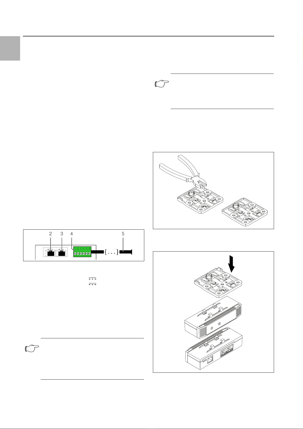
5.3.1 Connecting and installing the sensor cable
Fig. 2: Rear of the leak sensor
Key
2 CAN bus connection, 24 V
3 CAN bus connection, 24 V
4 Universal interface
5 Sensor cable
Leave the sensor cable on the transport coil until you are
ready to lay it.
To lay the sensor cable, carefully wind the transport
coil so that the cable is unrolled without twisting, and
positioned directly at the installation location.
Connect the sensor cable connector to the universal
interface (fig. 2, item 4).
Lay the sensor cable on the floor inside the area to be
monitored.
To do so, first stick the supplied retaining clips to the
floor using the adhesive.
Then press the sensor cable into the clips.
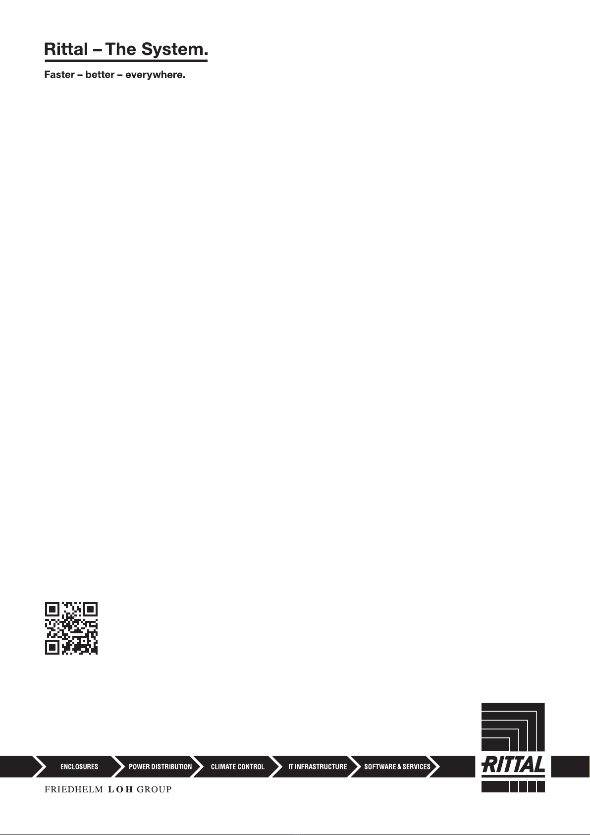
5.3.2 Installing the electronic unit with the pro-
vided bracket on the enclosure frame
The provided bracket is used for installation of the elec-
tronic unit on the frame of an IT enclosure.
For installation on a TS IT enclosure, break off the pro-
truding lugs at the rear of the bracket.
Fig. 3: Preparing the bracket for installation on a TS IT enclo-
sure
Place the leak sensor on the bracket from above.
Fig. 4: Attaching the sensor to the bracket
Move the sensor sideways slightly on the bracket so
that it latches into place.
Note:
The sensor cable must not be twisted or
kinked while unrolling, and must not be trod-
den on after laying. Otherwise, a short-circuit
may occur, leading to a defect in the sensor
cable.
Note:
The sensor cable has a section of approxi-
mately 2.5 m at the connection end where no
leaks are detected. The start of the sensor
cable itself is indicated by a yellow marker.

Rittal CMC III leak sensor, 15 m 9
5 Installation
EN
Fig. 5: Latching the sensor into place on the bracket
Fasten the bracket, including leak sensor, at the de-
sired position in the enclosure or the IT enclosure by
making a quarter-turn of the connector.
Fig. 6: Mounting the sensor in the enclosure or IT enclosure
Optionally secure the bracket using the two screws in-
cluded in the scope of delivery.
Fig. 7: Optional securing of the bracket
5.3.3 Installing the electronic unit with the pro-
vided bracket on a system chassis
The provided bracket is used for installation of the elec-
tronic unit on a system chassis.
Place the leak sensor on the bracket from above and
latch it similar to the installation on the enclosure
frame.
Fasten the bracket, including leak sensor, at the de-
sired position in the enclosure on the system chassis
by making a quarter-turn of the connector.
Fig. 8: Fastening the sensor to a system chassis
Also always secure the bracket with the two provided
bolts.
5.3.4 Installing the electronic unit on a top-hat
rail
The sensor can also be mounted on a top-hat rail using
the bracket along with the spring clip included in the
scope of delivery.
First screw the bracket onto the spring clip provided
for installation on a top-hat rail.
Then place the leak sensor on the bracket and latch it
into place.
Fig. 9: Fastening the bracket to the spring clip
Latch the spring clip into place at the desired position
on the top-hat rail.

5 Installation
EN
10 Rittal CMC III leak sensor, 15 m
Fig. 10: Sensor with spring clip on the top-hat rail
5.4 Connecting the electronic unit
The CAN bus connection supplies the leak sensor with
the necessary operating voltage. There is no need to
connect a separate power supply unit.
Use a CAN bus connection cable to connect the leak
sensor to a CAN bus interface on the CMC III Process-
ing Unit or the neighbouring component on the CAN
bus (fig. 2, item 2).
The following CAN bus connection cables from the
CMC III accessories range may be used:
– DK 7030.090 (length 0.5 m)
– DK 7030.091 (length 1 m)
– DK 7030.092 (length 1.5 m)
– DK 7030.093 (length 2 m)
– DK 7030.480 (length 3 m)
– DK 7030.490 (length 4 m)
– DK 7030.094 (length 5 m)
– DK 7030.095 (length 10 m)
Fig. 11: Front of the leak sensor
Key
1 Multi-LED for status display
The sensor software is updated, if necessary, following
connection. The status LED of the leak sensor glows
blue throughout and also flashes purple during the entire
update process.
In addition, the status LED of the CMC III Processing
Unit flashes white and a corresponding message ap-
pears on the website.
The sensor update is complete when the following con-
ditions have been fulfilled:
1. The LEDs on the CAN bus connection of the sensor
are green.
2. The multi-LED of the sensor behind the front panel
flashes blue and also green or red, depending on the
status of the sensor.
Further components are connected as a daisy chain.
If necessary, connect another component (e.g. anoth-
er sensor type) to the second, free CAN bus interface
of the leak sensor (fig. 2, item 3).
Status change display:
– The two green and the two red CAN bus LEDs on
the CAN bus connection flash.
– The multi-LED of the Processing Unit flashes contin-
ually in the sequence green – orange – red.
– The multi-LED of the leak sensor flashes blue con-
tinuously.
Press the "C" button on the CMC III Processing Unit
(an initial audio signal will sound) and keep it pressed
for approx. 3 seconds until a second audio signal is
heard.
Status change display on the CAN bus LEDs
– Continuous green LEDs: CAN bus status "OK".
– Continuous red LEDs: CAN bus status defective.
Status change display on the multi-LED of the Pro-
cessing Unit
– Continuous green light: All devices connected to the
CAN bus have the status "OK".
– Continuous orange light: At least one device connect-
ed to the CAN bus has the status "Warning".
– Continuous red light: At least one device connected to
the CAN bus has the status "Alarm".
Status change display on the multi-LED of the leak
sensor
– Continuous blue flashing: Communication via the CAN
bus.
– Green flashing: When the measured value changes, or
at least every 5 seconds.
– Continuous red flashing: The leak sensor has the sta-
tus "Alarm".
– Continuous red light: Invalid measured value.
Note:
No settings can be made as long as the up-
date process is running.
Note:
See section 6.3.1 "Multi-LED displays" for a
list of all of the multi-LED displays.

Rittal CMC III leak sensor, 15 m 11
6 Operation
EN
6 Operation
6.1 Activating the leak sensor
After connecting the leak sensor to the CMC III Process-
ing Unit using a CAN bus connection cable, the leak
sensor will activate automatically (see section 5.4 "Con-
necting the electronic unit"). Separate activation is not
required.
6.2 Operating and display elements
Fig. 12: Front of the leak sensor
Key
1 Multi-LED for status display
Fig. 13: Rear of the leak sensor
Key
2 CAN bus connection, 24 V
3 CAN bus connection, 24 V
4 Universal interface
5Sensorcable
6.3 LED displays
A multi-LED for the status display is integrated into the
front of the leak sensor (fig. 12, item 1). Further LEDs are
located at the rear on the CAN bus connection (fig. 13,
items 2 and 3).
6.3.1 Multi-LED displays
The status of the leak sensor can be read on the multi-
LED.
Continuous light
Flashing codes
6.3.2 LED displays on the CAN bus connection
A red and a green LED are located on the CAN bus con-
nection. They display the status of the CAN bus.
6.4 Operating via the CMC III Processing
Unit website
After logging on to the CMC III Processing Unit, the web
interface for operating the device is displayed.
First select the "CMCIII-LEAK" entry in the navigation
area.
Similar to the CMC III Processing Unit, the Configura-
tion tab can be used to individually configure the access
rights for the leak sensor (Device Rights button) and
the alarm messages (Alarm Configuration button).
The Observation tab is used to configure all of the set-
tings for the leak sensor, such as the time delay for
changes to the status message.
In the following sections 6.4.1 "Device" and 6.4.2 "Leak-
age", only those parameters which you can modify are
described. There are also display values that provide in-
formation.
6.4.1 Device
General settings for the leak sensor are configured at the
"Device" level.
In addition, parameters that provide detailed information
about the leak sensor, such as the software and hard-
ware version, are also displayed. You should have such
information available, in particular to permit fast trouble-
shooting of queries with Rittal.
Colour Status
Red Invalid measured value
Tab. 1: Multi-LED continuously lit
Colour Status
Green When the measured value changes or, at
the latest, every 5 seconds.
Tab. 2: Multi-LED flashing codes
Purple A leak sensor software update is being car-
ried out.
Blue Communication via the CAN bus.
Red The leak sensor has the status "Alarm".
Colour Status
Green
(steady light)
Communication via the CAN bus possible.
Red (flash-
ing)
Transmission error.
Tab. 3: LEDs on the CAN bus connection
Parameter Explanation
Description Specific description of the leak sensor.
Location Installation location of the leak sensor.
Tab. 4: Settings at "Device" level
Colour Status
Tab. 2: Multi-LED flashing codes

6 Operation
EN
12 Rittal CMC III leak sensor, 15 m
6.4.2 Leakage
Leakage settings are configured at the "Leakage" level.
The following parameters are also displayed for the leak
sensor:
The sensor cable is divided into five zones: In the event
of a leak, the sensor indicates the zone where the leak is
located in the "Position" parameter. Depending on the
liquid's conductivity (e.g. with water/glycol mixtures or
heavily contaminated water), the lengths of the zones
may vary.
Parameter Explanation
DescName Specific description of the leakage meas-
ured.
Delay Time delay after which the status message
changes.
Tab. 5: Settings at "Leakage" level
Parameter Explanation
Position Sensor cable zone (zone 1 to zone 5)
where the leak was detected.
Status Current status of the leak sensor, taking
account of the time delay.
Tab. 6: Displays at "Leakage" level

Rittal CMC III leak sensor, 15 m 13
7 Storage and disposal
EN
7 Storage and disposal
7.1 Storage
If the device is not used for a long period, Rittal recom-
mends that it be disconnected from the mains power
supply and protected from damp and dust.
7.2 Disposal
Since the leak sensor consists mainly of the "housing"
and "circuit board" parts, the device must be passed on
to the electronic waste recycling system for disposal.

8 Technical specifications
EN
14 Rittal CMC III leak sensor, 15 m
8 Technical specifications
Technical specifications CMC III leak sensor, 15 m
Model No. DK 7030.440
W x H x D (mm) 110 x 30 x 40
Operating temperature range 0 °C…+55 °C
Storage temperature -45 °C…+85 °C
Operating humidity range 5%...95% relative humidity, non-condensing
Protection category of electronic unit IP 30 to IEC 60 529
Inputs and outputs
CAN bus (RJ 45) 2 x
Sensor cable interface 1 x
Operation/signals LED display OK/Alarm/CAN bus status
Tab. 7: Technical specifications

Rittal CMC III leak sensor, 15 m 15
9 Customer service addresses
EN
9 Customer service addresses
For technical queries, please contact:
Tel.: +49(0)2772 505-9052
E-mail: info@rittal.de
Homepage: www.rittal.com
For complaints or service requests, please contact:
Tel.: +49(0)2772 505-1855
E-mail: service@rittal.de
◾Enclosures
◾ Power Distribution
◾ Climate Control
◾ IT Infrastructure
◾ Software & Services
You can find the contact details of all
Rittal companies throughout the world here.
www.rittal.com/contact
RITTAL GmbH & Co. KG
Auf dem Stuetzelberg · 35745 Herborn · Germany
Phone +49 2772 505-0
E-mail: info@rittal.de · www.rittal.com
07.2020 / D-0000-00000712-01-EN
Table of contents
Other Rittal Security Sensor manuals

Popular Security Sensor manuals by other brands

Ledvance
Ledvance Osram LIGHTIFY manual

Endress+Hauser
Endress+Hauser Prosonic FDU83 Safety instructions for electrical apparatus certified for use in explosion-hazardous areas

THORLABS
THORLABS APD410 Series Operation manual

EUCHNER
EUCHNER MGB-L**B-PN series operating instructions

ACS
ACS ACR122U System manual

PSM
PSM LD161 installation guide


