manuals.online logo
Brands
  1. Home
  2. •
  3. Brands
  4. •
  5. GJD
  6. •
  7. Security Sensor
  8. •
  9. GJD MX25 User manual

GJD MX25 User manual

-1-12101
MX25
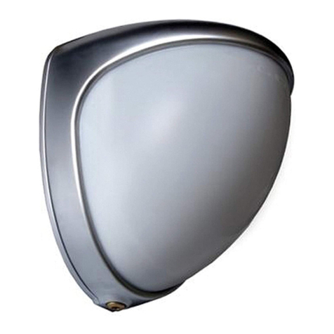
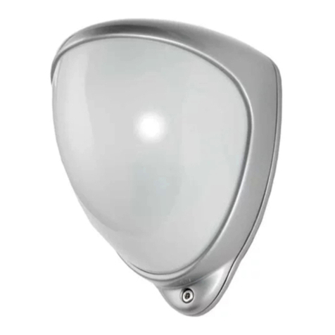
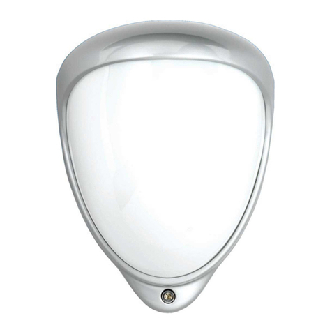
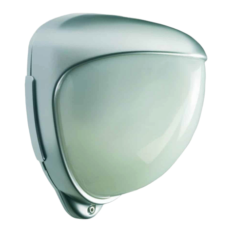
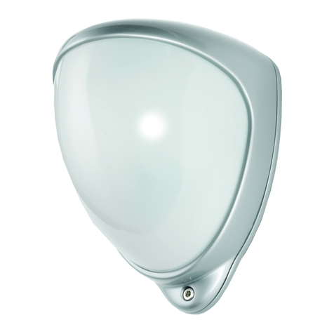
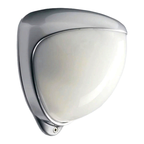
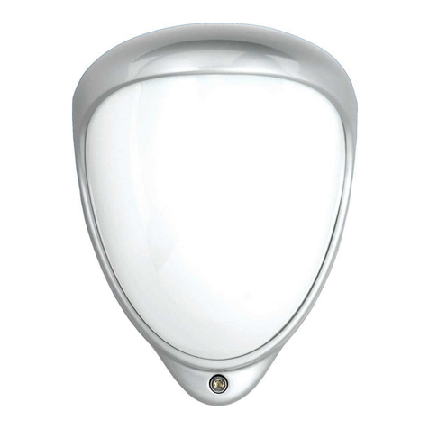
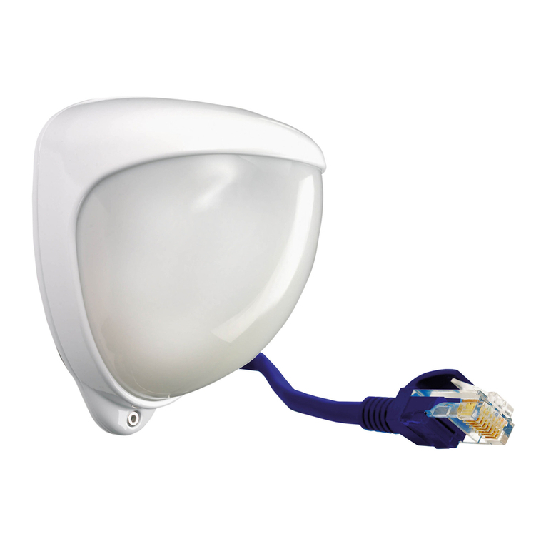
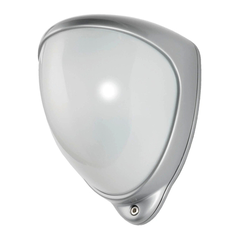
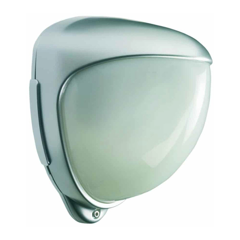
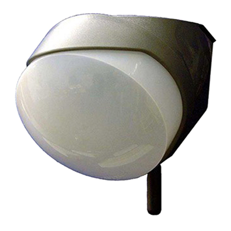
GJD102 Quad PIR Movement Detector
Package Contents
Package Contains:
●1 x MX25
●1 x Allen Key
●2 x 27mm wall plugs
●2 x 27mm sc ews
●3 x Tampe Feet
●1 x Tampe Cup
●1 x Installation manual
Introduction
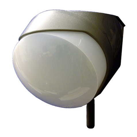
The MX25 is an att actively styled, 25 met e Passive Inf a-
ed (PIR) detecto , with advanced featu es such as dual
tampe switches fo case and wall-mount tampe detection,
senso mounted white-light filte and zone blanking using
ve tical cu tain shutte s and ho izontal masking fo p ecise
a ea cove age.
5. When the detecto is aligned, connected, and
p og ammed to suit the installation, eplace the
f ont cove and lock in place.
The multifunction lens fitted to MX25 p oduces 5 long ange
beams and 5 medium to sho t ange cu tain PIR beams
(see Figu e 2). The PIR ci cuit y detects changes in heat
and movement in the beam patte n; the efo e items such as
t ees, sh ubs, ponds, boile flues, and animals should be
conside ed when positioning the detecto .
Note: The PIR sensor is more sensitive to movement
across the beams, and less sensitive to movement
directly towards or away from the beams.
The detecto module is fitted with two sliding shutte s to
educe the detection angle.
When cove age exceeds the desi ed detection a ea, adjust
the module as equi ed and mask off any beams, eithe
ve tically o ho izontally, to avoid unwanted detection.
Use po tions of the self-adhesive silve mask applied to the
ea , smooth side of the lens as shown in Figu e 2. Always
eplace the lens the co ect way up to ensu e exact beam
patte n cove age (top of the lens is ma ked TOP).
When mounted at heights above 3 met es the e could be a
significant eduction in the ange of detection and the ta get
will have to move a g eate distance within the field of view
befo e an ala m is gene ated.
Quick Installation
1. Mount and connect the detecto following the
inst uctions given late in this manual.
2. Configu e p og amming switches as equi ed
efe ing to inst uctions given late in this manual.
3. Apply supply voltage to the unit. The blue detection
LED flashes th ee times.
4. Wait app oximately 2 to 3 minutes to allow the
detecto to settle.
Note: The front cover must be fitted when walk
testing.
The default settings a e:
●Range: 25 mete s
●Pulse count: 1 (always set to 1 du ing walk est)
●Detection LED: On ( ecommend fo set up p ocess)
Mounting The Unit
Multibeam Alignment & Masking
onfiguration Mounting
Height
(Metres)
Tilt (°) Max.
Range
(Metres)
Reference
Multibeam
(Optimum)
3 5 25 Figu e 3
Pet Immunity * 1.5 -5 25 Figu e
4 & 5
Masking onfigurations For Maximum Range
* Black a ea should be masked fo pet alley applications up to 25 mete s
(see figu e 5).
Du ing installation, p otect the elect onics against wate , as
t apped moistu e can affect o damage the unit.
1. D ill the wall to accept the two fixing sc ews, the
cable ent y, and the tampe cup (if used).
Note: We recommend using the tamper cup on
uneven wall surfaces.
2. Remove the cove assembly by loosening the
locking sc ew using the allen key p ovided. The
cove hinges f om the top and lifts out of the
location slot.
3. Feed the cables into the cable ent y and Sc ew the
unit to the wall ensu ing that the tampe pin is
co ectly located and that the tampe mic oswitch is
closed.
Th ee spa e tampe feet of diffe ent lengths a e
p ovided to aid installation. The tampe foot is a
push fit and can be emoved by ca efully pulling it
f om the pin.
4. Connect the cables to the sc ew-te minal block on
the back of the detecto PCB (see Figu e 1).
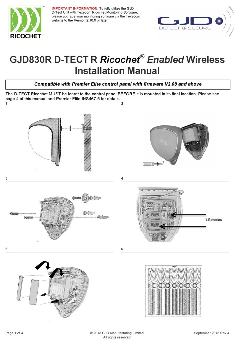
Figu e 6 shows the patte n fo the maximum ange in the
optimum position (see Figu e 10).
Figu es 7 and 8 illust ates alignment ecommendations fo
when the detecto is mounted close to a wall.
The alignment shown in Figu e 7 is not ecommended. If
the detecto module is o ientated at an angle of 90° to the
pe imete , the mounting wall may cut off sho t and medium
ange beams. The long ange beam will still detect an
int ude , howeve the wall can cause false ala ms when
heated by sunlight.
Figu e 8 shows the ecommended alignment. The detecto
module is o ientated at a 55° angle to the pe imete . As a
esult, sho t and medium ange beams a e pa allel to the
pe imete , but the detection ange along the pe imete is
educed.
-2-12101
Programming
Walk Test
Note: It is recommended that the detection LED be
enabled during walk test to aid in set up. The detection
LED lights each time the MX25 detects your presence.
Note: When you conduct a walk test, make sure that the
front cover is in place. Do not conduct walk tests with
the cover removed.
The ange of the detecto inc eases without the p otective
f ont cove . The efo e the f ont cove must be fitted to
establish the co ect beam patte n. Use p og amming cha t
to adjust the ange as necessa y. Pan and tilt the lens
module ove the field of view to obtain the co ect cove age
a ea.
Option Switch onfiguration Reference
LED ON Switch 1: On (Up) Figu e 10
LED OFF Switch 1: Off (Down) Figu e 11
Pulse Count 1 Switch 2: Off (Down) Figu e 12
Pulse Count 2 Switch 2: On (Up) Figu e 13
10 Met e Range Switch 3: Off (Down)
Switch 4: Off (Down)
Figu e 14
15 Met e Range Switch 3: Off (Down)
Switch 4: On (Up)
Figu e 15
20 Met e Range Switch 3: On (Up)
Switch 4: Off (Down)
Figu e 16
25 Met e Range Switch 3: On (Up)
Switch 4: On (Up)
Figu e 17
Shaded settings a e facto y defaults
To change any of the MX25 settings, change the
configu ation of the p og amming switches (see Figu e 9)
as equi ed. switch 1 cont ols detection LED state, switch 2
cont ols Pulse Count, and switches 3 and 4 cont ol ange.
Example: To change the ange to 15 met es:
1. Set switch 3 to Off (down position).
2. Set switch 4 to On (up position).
Programming ptions Definitions
Pulse ount
This is the numbe of times the unit has to detect on both of
its senso s befo e signalling an output.
LED
LED Off – LED disabled.
LED On – LED signals a detection.
Programming hart
Specifications
Detection Area P og ammable between 10 & 25
met es.
overage 90 deg ees detection angle, 25m x
25m cove age max.
Adjustment 180 deg ee pan + 90 deg ee tilt.
Fresnel Lens
10 zones fo each Py o pai , which
can be masked with cu tain slide s
and special masking tape (supplied).
ustomised Optics Double silicon shielded quad element
eliminates 50,000 Lux of white light.
Outputs Silent solid state magnetically
immune.
No. 1
N / OPEN
Volt f ee elay signal contact
24VAC/DC @ 50mA with an integ al
25Ω esisto .
Ala m time 5 seconds.
No. 2
N / LOSED
Volt f ee elay signal contact
24VAC/DC @ 50mA with an integ al
25Ω esisto .
Ala m time 5 seconds.
T
Tamper
Volt f ee, no mally open switch output
12VDC @ 25mA.
Tamper Switches F ont and ea tampe switches; case
open and emoval f om wall.
Pulse ount 1 - 2.
Power Input 9 to 15 VDC.
urrent 8mA (12V nominal).
Operating Temp.
-20 to +55 Centig ade
Confo mal coated elect onics fo
inc eased stability.
Housing High impact ABS.
Protection Rating IP 55.
Dimensions 84 x 106 x 72 mm.
Mounting Height Va iable – optimum height 3 met es.
E Mark
GJD ese ve the ight to amend specifications without p io notice
GJD Manufacturing Limited
Unit 2 Bi ch Indust ial Estate
Whittle Lane
Heywood
Lancashi e
OL10 2SX
Sales: +44 (0) 1706 363 998
Technical: +44 (0) 1706 363 990
Fax: +44 (0) 1706 363 991
Email: in[email protected]k
Web: www.gjd.co.uk
-3-12101
12
3 4
5 6
7 8
9 10
P og amming Switches
Led On
-4-12101
11 12
13 14
15 16
Pulse Count 1
Pulse Count 2 Range 10 Met es
Range 15 Met es
Range 20 Met es
Range 25 Met es
17
Led Off

Other GJD Security Sensor manuals

GJD Ricochet GJD850R D-TECT R User manual

GJD

GJD Ricochet GJD850R D-TECT R User manual

GJD D-TECT R Ricochet GJD830R User manual

GJD

GJD D-TECT R Ricochet GJD830R User manual

GJD D-TECT Dual AM User manual

GJD

GJD D-TECT Dual AM User manual

GJD D-Tect 1 User manual

GJD

GJD D-Tect 1 User manual

GJD D-TECT X 50 MKIII User manual

GJD

GJD D-TECT X 50 MKIII User manual

GJD D-TECT Dual Tech GJD360/AM User manual

GJD

GJD D-TECT Dual Tech GJD360/AM User manual

GJD Dual Tech GJD360 User manual

GJD

GJD Dual Tech GJD360 User manual

GJD D-TECT 40 IP User manual

GJD

GJD D-TECT 40 IP User manual

GJD D-TECT Universal Dual Tech User manual

GJD

GJD D-TECT Universal Dual Tech User manual

GJD D-TECT 60 User manual

GJD

GJD D-TECT 60 User manual

GJD GEM User manual

GJD

GJD GEM User manual

GJD D-TECT R Ricochet GJD830R User manual

GJD

GJD D-TECT R Ricochet GJD830R User manual

GJD Quad PIR MX20 HT User manual

GJD

GJD Quad PIR MX20 HT User manual

GJD D-TECT Dual ABS User manual

GJD

GJD D-TECT Dual ABS User manual

GJD D-TECT 1 User manual

GJD

GJD D-TECT 1 User manual

GJD D-TECT 50 User manual

GJD

GJD D-TECT 50 User manual

GJD GJD140 User manual

GJD

GJD GJD140 User manual

GJD D-TECT 2 IP User manual

GJD

GJD D-TECT 2 IP User manual

GJD D-tect Dual HT GJD362 User manual

GJD

GJD D-tect Dual HT GJD362 User manual

GJD Opal XL User manual

GJD

GJD Opal XL User manual

GJD Mini Opal User manual

GJD

GJD Mini Opal User manual

GJD D-TECT Dual AM GJD369 User manual

GJD

GJD D-TECT Dual AM GJD369 User manual

GJD D-TECT 3 IP GJD260 User manual

GJD

GJD D-TECT 3 IP GJD260 User manual

GJD D-TECT 50 IP User manual

GJD

GJD D-TECT 50 IP User manual

Popular Security Sensor manuals by other brands

Pilz PSEN cs1.1n operating manual

Pilz

Pilz PSEN cs1.1n operating manual

AFRISO AHD 20 operating instructions

AFRISO

AFRISO AHD 20 operating instructions

Tractel tirfor TU6P Operating and maintenance instruction

Tractel

Tractel tirfor TU6P Operating and maintenance instruction

Powerfix Profi Z31385 Operation and safety notes

Powerfix Profi

Powerfix Profi Z31385 Operation and safety notes

Guardian Fall Protection HLL System instruction manual

Guardian Fall Protection

Guardian Fall Protection HLL System instruction manual

Southwest Microwave INTREPID Technical manual

Southwest Microwave

Southwest Microwave INTREPID Technical manual

Bircher Reglomat ProLoop 2 Translation of the original instructions

Bircher Reglomat

Bircher Reglomat ProLoop 2 Translation of the original instructions

Smarteh LPC-2.SM5 user manual

Smarteh

Smarteh LPC-2.SM5 user manual

Alarmtech CD 470 installation manual

Alarmtech

Alarmtech CD 470 installation manual

Honeywell IS312B Quick installation guide

Honeywell

Honeywell IS312B Quick installation guide

Hilti PS 38 operating instructions

Hilti

Hilti PS 38 operating instructions

Molecular Devices SpectraMax Paradigm Safety guide

Molecular Devices

Molecular Devices SpectraMax Paradigm Safety guide

sewerin UtiliTrac manual

sewerin

sewerin UtiliTrac manual

MJ Research PTC-200 DNA Engine Operation manual

MJ Research

MJ Research PTC-200 DNA Engine Operation manual

Whelen Engineering Company 2022 Series installation guide

Whelen Engineering Company

Whelen Engineering Company 2022 Series installation guide

Leuze electronic RSL 430 Original operating instructions

Leuze electronic

Leuze electronic RSL 430 Original operating instructions

Hytronik HC403VRC-KD Installation and instruction manual

Hytronik

Hytronik HC403VRC-KD Installation and instruction manual

LEGRAND Wattstopper FDP-301SR manual

LEGRAND

LEGRAND Wattstopper FDP-301SR manual

manuals.online logo
manuals.online logoBrands
  • About & Mission
  • Contact us
  • Privacy Policy
  • Terms and Conditions

Copyright 2025 Manuals.Online. All Rights Reserved.