Rivera FS8M User manual

FS8M External MIDI Interface 1.0 p 1
External MIDI Interface
OWNERS MANUAL
Version 1.0
April, 2002
FS8M External MIDI Interface 1.0 p 2
INTRODUCTION
The FS8M External MIDI interface replaces the FS8 footswitch and allows MIDI control
of the amplifier. You cannot use the footswitch and the interface at the same time.
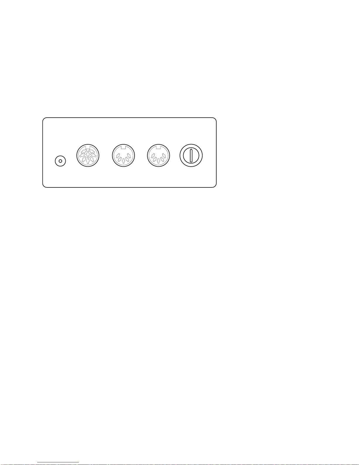
CONNECTORS ON THE PANEL
8
7
6
5
4
3
2
1
0
15
14
13
12
11
10
9
TO
AMP
6-15
VDC
PIN
NEG. MIDI
IN MIDI
THRU MIDI
CHANNEL
6-15 VDC PIN NEG.
The interface requires DC power to operate. This power can be obtained from a wall-
wart style power supply, or from the 12VDC POWER OUT connector on the Rivera
Head Master.
Depending on which model you ordered, you should have received a power supply or a
cable.
If it ever becomes necessary to replace the power supply, here are a few guidelines:
Because it is internally regulated and does not draw much current, the interface is very
tolerant of voltage. Any DC voltage from about 6 to 15V will work. The size and polarity
of the connector was deliberately chosen to be compatible with commonly available
stomp box power supplies of the wall-wart variety. Supplies made by Roland or Korg
should work fine.
WARNING!
There is no agreement among power supply manufacturers on the polarity of
connectors. You MUST select a power supply with the center contact NEGATIVE and
the outer barrel POSITIVE or the unit will not work! Also, you must use a DC supply. An
AC supply WILL NOT work! DO NOT assume that just because the connector fits, it will
work. Read the label on the power supply, and if it is not labeled, use a voltmeter.
TO AMP
Use a cable with 8 pin male DIN connectors on each end. You should have received a
cable with your unit. Be careful with this cable. It IS NOT commonly available in most
music or electronic stores.

FS8M External MIDI Interface 1.0 p 3
If it ever becomes necessary to replace it, you can order one from Rivera or make it
yourself. It does not require shielded cable, and the pins are wired straight through.
(1-1, 2-2 etc.)
MIDI IN
Standard MIDI input. Use this to connect any standard MIDI controller.
MIDI THRU
Standard MIDI thru, passes data from the MIDI IN to additional MIDI gear.
The Midi Channel Selector Switch
8
7
6
5
4
3
2
1
0
15
14
13
12
11
10
9
The Interface uses a rotary switch to select the MIDI channel. It is a high quality switch,
and is much easier to use than the DIP switches used by some manufacturers.
Unfortunately, it is numbered in a way that can create confusion.
As shown on the diagram, the switch is numbered from 0-15.
Most MIDI devices define the MIDI channels as 1-16
So, it is necessary to add 1 to the number on the switch to get the MIDI channel
SWITCH POSITION 5 = MIDI CHANNEL 6
So, why is the switch labeled wrong?
In the world of electronics and programming, it is not labeled wrong.
It selects one of 16 four digit binary numbers, 0-15 is 0000-1111 in binary.
It is labeled correctly for what it does.
Internally, MIDI gear uses channels 0-15.
Long ago, MIDI manufacturers decided that musicians would be uncomfortable.
with channel zero, so they decided to add a 1 to the actual value.
Counting From Zero
As you may or may not know, computer programmers start counting from zero instead
of one.
Most people would count a list of items like this:
One, two, three, I have three items.
A programmer would do the same if he was counting the items, but if he was using
numbers as names he would name the first item "item number zero," the second would

FS8M External MIDI Interface 1.0 p 4
be called "item number one" and the third "item number two." Programmers call this
process enumerating the items.
Why do programmers do this?
Here is an example:
If you are standing in front of your house, how far do you have to walk to get to your
neighbor? You have to walk ONE house unit away.
How far do you have to walk to get to your OWN house? Since you are already standing
in front of your house, you have to walk ZERO house units away.
Zero is the starting point, you move from zero some number of units.
Programmers frequently deal with lists of things. The same logic applies to these lists. If
you are looking at the first item in a list, how far do you have to move to look at the
second? You have to move ONE unit.
How far do you have to move to look at the first item? Since you are already looking at
it, you move ZERO.
Another way of looking at it is to ask the question, "How many single digit numbers are
there?" There are 10. They are: 0, 1, 2, 3, 4, 5, 6, 7, 8 and 9. You don't get to the
number 10 until you add another digit. Programmers can't afford to be wasteful, they
use ALL of the digits, especially zero.
This is also the root of the controversy over the year 2000. If you start counting at zero,
2000 is the millennium.
MIDI is a computer communication protocol, and internally, it starts from zero.
MIDI Channels are actually numbered 0-15 and Program Changes are numbered 0-
127.
But, since most people are not comfortable counting from zero, MOST MIDI instruments
add an extra one and define MIDI Channels 1-16 and Program Changes 1-128. NOT
ALL MIDI instruments do this!
We debated long and hard over which philosophy to adopt. In the end we chose to
follow the de-facto standard and number from one. We believed that this decision would
result in less confusion and fewer problems.
One problem we could not avoid was the numbering of the MIDI Channel Selector
switch. The manufacturer of the switch numbered it from 0-15. These are in fact the
actual numbers the switch uses. We had no control over the labeling.
The unfortunate result of this mismatch is that you have to set the MIDI Channel
Selector Switch to 0 to select MIDI Channel 1.

FS8M External MIDI Interface 1.0 p 5
MIDI Control
Overview
The MIDI interface takes the place of the FS8 pedal, and controls all functions that were
originally controlled by the pedal. No more. No less. In other words, the interface does
not provide any additional control beyond that which the FS8 provides.
The interface responds to MIDI Program Change Commands only.
It can be controlled by the Rivera Head Master foot-operated MIDI controller or by any
standard MIDI controller.
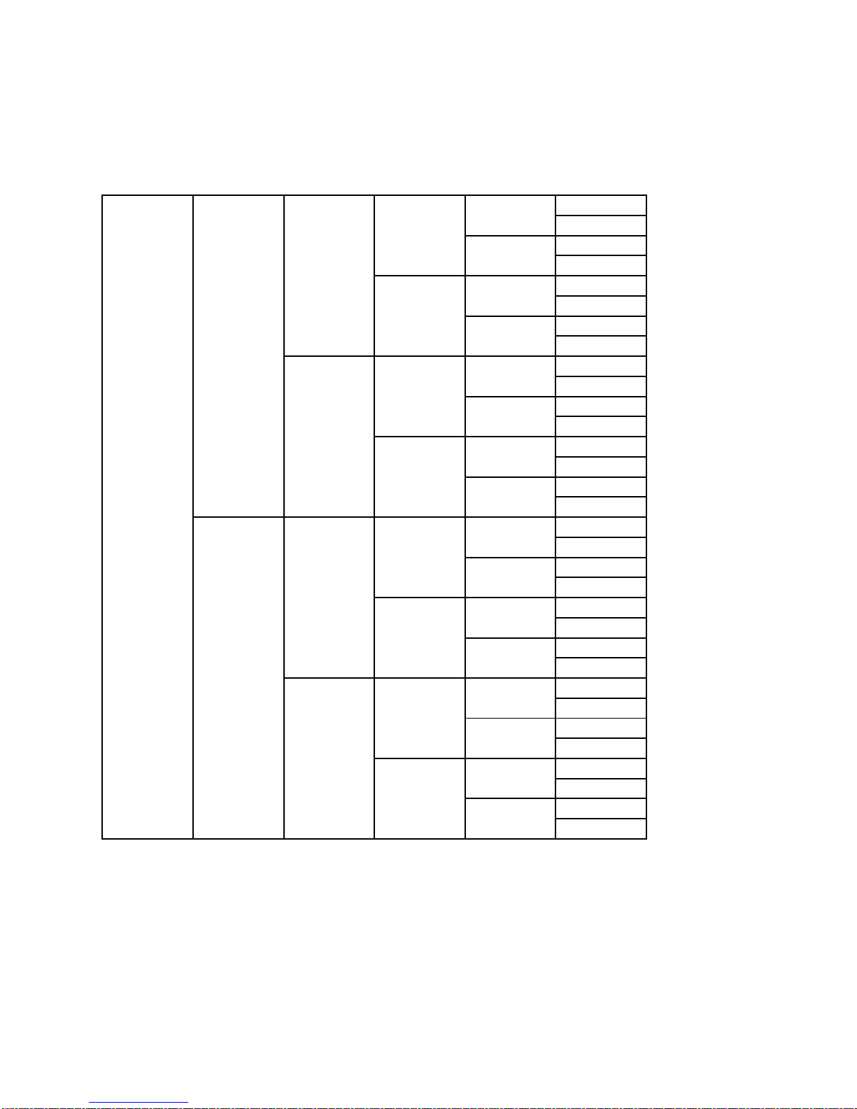
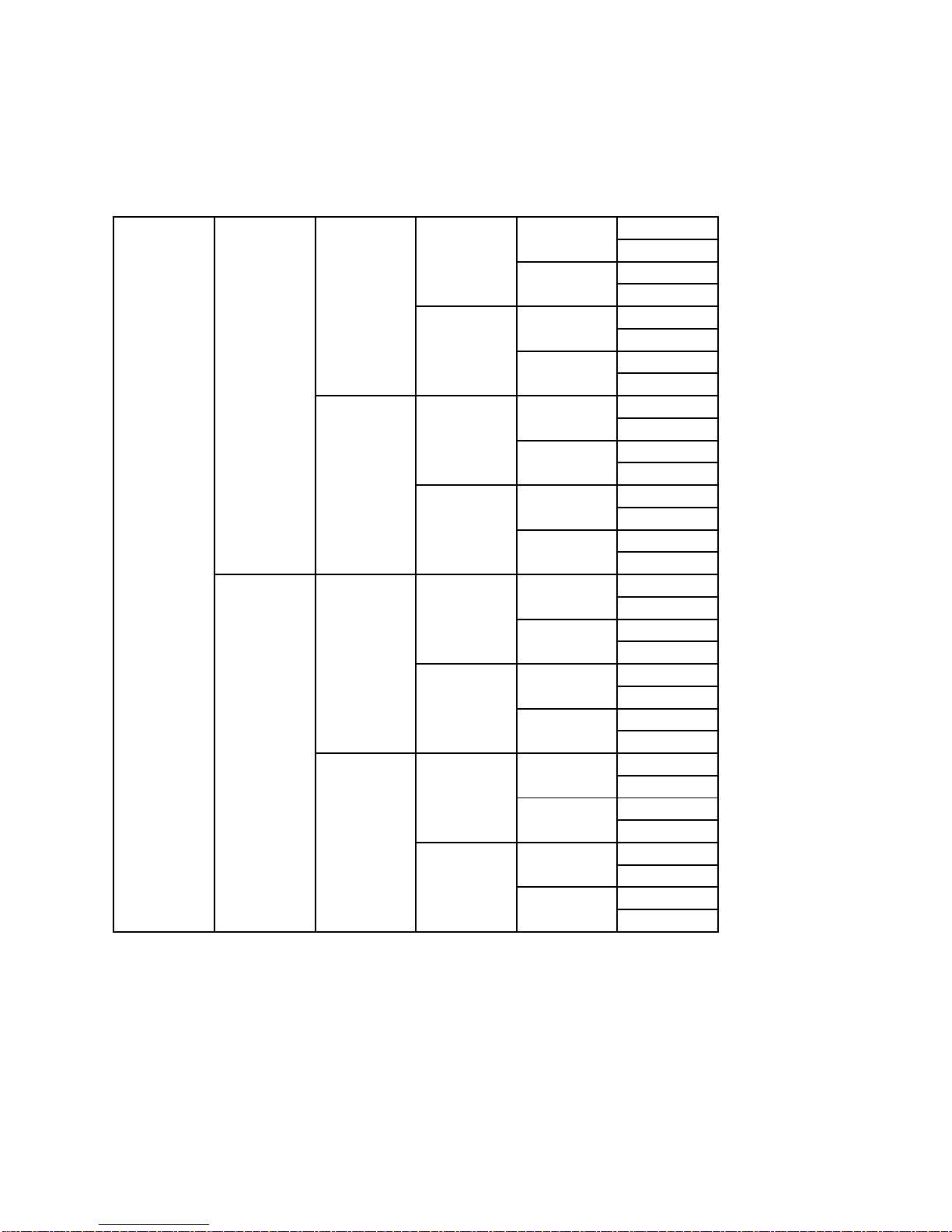
Combinations And Separate Functions
Two types of commands are provided - Combinations and Separate Functions.
Combinations
When the amp receives a Combination Command, ALL MIDI controllable values are
changed.
For example Program Change 43 selects:
Channel 2
Boost 1 OFF
Boost 2 ON
Boost 3 OFF
Effects Loop OFF
Separate Functions
Program Change commands for separate functions have also been defined.
Separate functions change ONE value only, leaving all others unchanged.
Knucklehead Reverb Compatibility
The program change commands were chosen to be as identical as possible to the
commands used by the Knucklehead Reverb. The only difference is that the FS8 does
not control Reverb (because the Bonehead has no reverb). This design explains why
there is a column marked UNUSED on the chart.
Contact Me
My name is Mike Peterson
I designed the FS8M and wrote the manual.
If you have any questions, comments, praise or criticism, please let me know.
FS8M External MIDI Interface 1.0 p 6
OFF
ON
OFF
ON
OFF
ON
OFF
ON
OFF
ON
OFF
ON
OFF
ON
OFF
ON
OFF
ON
OFF
ON
OFF
ON
OFF
ON
OFF
ON
OFF
ON
OFF
ON
OFF
ON
1
2
3
4
5
6
7
8
9
10
11
12
13
14
15
16
17
18
19
20
21
22
23
24
25
26
26
28
29
30
31
32
OFF
OFF
ON
ON
OFF
OFF
ON
ON
OFF
OFF
ON
ON
OFF
OFF
ON
ON
OFF
OFF
ON
ON
OFF
OFF
ON
ON
OFF
OFF
ON
ON
OFF
OFF
ON
ON
OFF
OFF
OFF
OFF
ON
ON
ON
ON
OFF
OFF
OFF
OFF
ON
ON
ON
ON
OFF
OFF
OFF
OFF
ON
ON
ON
ON
OFF
OFF
OFF
OFF
ON
ON
ON
ON
OFF
OFF
OFF
OFF
OFF
OFF
OFF
OFF
OFF
OFF
OFF
OFF
OFF
OFF
OFF
OFF
OFF FXUNUSEDBOOST3BOOST2
BONEHEAD MIDI PROGRAM CHANGES
COMBINATIONS
BOOST1
OFF
OFF
OFF
OFF
OFF
OFF
OFF
OFF
OFF
OFF
OFF
OFF
OFF
OFF
OFF
1
1
1
1
1
1
1
1
1
1
1
1
1
1
1
1
1
1
1
1
1
1
1
1
1
1
1
1
1
1
1
1
CHANNEL
ON
ON
ON
ON
ON
ON
ON
ON
ON
ON
ON
ON
ON
ON
ON
ON
ON
ON
ON
ON
ON
ON
ON
ON
ON
ON
ON
ON
ON
ON
ON
ON
FS8M External MIDI Interface 1.0 p 7
OFF
ON
OFF
ON
OFF
ON
OFF
ON
OFF
ON
OFF
ON
OFF
ON
OFF
ON
OFF
ON
OFF
ON
OFF
ON
OFF
ON
OFF
ON
OFF
ON
OFF
ON
OFF
ON
33
34
35
36
37
38
39
40
41
42
43
44
45
46
47
48
49
50
51
52
53
54
55
56
57
58
59
60
61
62
63
64
OFF
OFF
ON
ON
OFF
OFF
ON
ON
OFF
OFF
ON
ON
OFF
OFF
ON
ON
OFF
OFF
ON
ON
OFF
OFF
ON
ON
OFF
OFF
ON
ON
OFF
OFF
ON
ON
OFF
OFF
OFF
OFF
ON
ON
ON
ON
OFF
OFF
OFF
OFF
ON
ON
ON
ON
OFF
OFF
OFF
OFF
ON
ON
ON
ON
OFF
OFF
OFF
OFF
ON
ON
ON
ON
OFF
OFF
OFF
OFF
OFF
OFF
OFF
OFF
OFF
OFF
OFF
OFF
OFF
OFF
OFF
OFF
OFF FXUNUSEDBOOST3BOOST2
BONEHEAD MIDI PROGRAM CHANGES
COMBINATIONS
BOOST1
OFF
OFF
OFF
OFF
OFF
OFF
OFF
OFF
OFF
OFF
OFF
OFF
OFF
OFF
OFF
2
2
2
2
2
2
2
2
2
2
2
2
2
2
2
2
2
2
2
2
2
2
2
2
2
2
2
2
2
2
2
2
CHANNEL
ON
ON
ON
ON
ON
ON
ON
ON
ON
ON
ON
ON
ON
ON
ON
ON
ON
ON
ON
ON
ON
ON
ON
ON
ON
ON
ON
ON
ON
ON
ON
ON

FS8M External MIDI Interface 1.0 p 8
OFF
ON
OFF
ON
OFF
ON
OFF
ON
OFF
ON
OFF
ON
OFF
ON
OFF
ON
OFF
ON
OFF
ON
OFF
ON
OFF
ON
OFF
ON
OFF
ON
OFF
ON
OFF
ON
65
66
67
68
69
70
71
72
73
74
75
76
77
78
79
80
81
82
83
84
85
86
87
88
89
90
91
92
93
94
95
96
OFF
OFF
ON
ON
OFF
OFF
ON
ON
OFF
OFF
ON
ON
OFF
OFF
ON
ON
OFF
OFF
ON
ON
OFF
OFF
ON
ON
OFF
OFF
ON
ON
OFF
OFF
ON
ON
OFF
OFF
OFF
OFF
ON
ON
ON
ON
OFF
OFF
OFF
OFF
ON
ON
ON
ON
OFF
OFF
OFF
OFF
ON
ON
ON
ON
OFF
OFF
OFF
OFF
ON
ON
ON
ON
OFF
OFF
OFF
OFF
OFF
OFF
OFF
OFF
OFF
OFF
OFF
OFF
OFF
OFF
OFF
OFF
OFF FXUNUSEDBOOST3BOOST2
BONEHEAD MIDI PROGRAM CHANGES
COMBINATIONS
BOOST1
OFF
OFF
OFF
OFF
OFF
OFF
OFF
OFF
OFF
OFF
OFF
OFF
OFF
OFF
OFF
3
3
3
3
3
3
3
3
3
3
3
3
3
3
3
3
3
3
3
3
3
3
3
3
3
3
3
3
3
3
3
3
CHANNEL
ON
ON
ON
ON
ON
ON
ON
ON
ON
ON
ON
ON
ON
ON
ON
ON
ON
ON
ON
ON
ON
ON
ON
ON
ON
ON
ON
ON
ON
ON
ON
ON
CH 1
CH 2
CH 3
TOGGLE BOOST 1
TOGGLE BOOST 2
TOGGLE BOOST 3
97
98
99
100
101
102
UNUSED 103
TOGGLE FX 104
TOGGLE ACTIVE BOOST 105
SEPARATE FUNCTIONS
Table of contents
Other Rivera Media Converter manuals


Popular Media Converter manuals by other brands


H&B
H&B TX-100 Installation and instruction manual

Bolin Technology
Bolin Technology D Series user manual

IFM Electronic
IFM Electronic Efector 400 RN30 Series Device manual

GRASS VALLEY
GRASS VALLEY KUDOSPRO ULC2000 user manual

Linear Technology
Linear Technology DC1523A Demo Manual

Lika
Lika ROTAPULS I28 Series quick start guide

Weidmuller
Weidmuller IE-MC-VL Series Hardware installation guide

Optical Systems Design
Optical Systems Design OSD2139 Series Operator's manual

Tema Telecomunicazioni
Tema Telecomunicazioni AD615/S product manual

KTI Networks
KTI Networks KGC-352 Series installation guide

Gira
Gira 0588 Series operating instructions

Lika
Lika SFA-5000-FD user guide