RIX MB-115 User manual

RIX
COMPRESSORS
MICROBOOST
Owner’s
Manual
MB-115
MB-230
PLICABILITY
[CD]
February
19,
2004
AP
WARNING!!!
To
prevent
FIRE,
SERIOUS
INJURY
and/or
DEATH,
it
is
the
User's
responsibility
to
ensure
that
all
parts
used
in
the
compression
assembly
and
gas
plumbing
of
a
RIX
Oxygen
or
Nitrox
compressor
are
cleaned
for
oxygen
service.
Cleaning
should
be
in
accordance
with
Compressed
Gas
Association
G-4.1.
Factory
oxygen
cleaned
parts
are
denoted
by
an
“X”
prefix
at
the
beginning
of
the
part
number.
it
is
the
Buyers
responsibility
to
maintain
the
cleanliness
of
factory-cleaned
parts
throughout
installation
and
start-up.
Furthermore,
non-factory
supplied
parts
will
void
all
warranties,
as
improper
materials
can
cause
oxygen
fires
resulting
in
serious
fires
injury
and/or
death.
FOR
ALL
REPAIRS:
1)
Refer
to
the
applicable
service
manual
for
assembly
instructions
2)
Refer
to
applicable
compressor
start-up
instructions
after
all
repairs
INTRODUCTION
Congratulations
on
your
purchase
of
the
Rix
Microboost
compressor.
We
anticipate
that
with
proper
care
you
will
get
many
years
of
satisfactory
performance
from
this
compressor.
This
manual
is
prepared
to
help
you
operate
this
equipment
safely
and
so
that
you
get
the
most
benefit
from
this
package.
Please
read
it
carefully.
This
equipment
is
protected
by
warranty,
a
copy
of
which
should
have
been
provided
separately
by
your
dealer.
We
suggest
that
you
read
the
warranty
policy
to
fully
understand
your
coverage
and
your
responsibilities
of
ownership.
Rix
recommends
that
all
servicing
be
done
by
trained
and
qualified
personnel.
Rix
recommends
that
you
contact
our
offices
at
707-747-5900
for
a
list
of
qualified
service
centers.
Rix
Industries
4900
industrial
Way
Benicia,
CA
94510
Phone
(707)
747-5900
Fax
(707)
747-9200
APPLICABILITY
[
ABCD]
1
INTRODUCTION
Safety
This
electromechanical
equipment
is
designed
to
produce
high
pressure
gas.
Operating
personnel
must
follow
these
safety
requirements
at
all
times
to
avoid
injury
to
personnel
or
damage
to
property.
Keep
away
from
live
circuits.
Do
not
attempt
to
replace
components
or
make
adjustments
unless
the
power
to
the
compressor
has
been
disconnected
and
all
pressure
relieved.
Never
operate
with
safety
devices
removed
or
disabled. This
includes
guards
for
moving
objects,
protection
from
high
temperature
surfaces,
pressure
relief
valves,
pressure
switches,
or
covers
over
electrical
components.
When
compressing
oxygen
it
is
critical
that
surfaces
in
contact
with
oxygen
be
kept
clean
and
free
from
contamination,
especially
hydrocarbon
contamination
or
any
flammable
material.
This
compressor
is
shipped
oxygen
clean
and
must
be
maintained
that
way
to
avoid
the
hazard
of
explosion
or
fire.
Safety
warnings
are
provided
in
a
variety
of
forms,
including:
Safety
Labels-located
on
the
equipment
Safety
Messages-
provided
in
this
manual
and
proceeded
by
a
safety
alert
label,
DANGER,
WARNING,
CAUTION,
and
NOTE.
You
will
likely
be
killed
or
seriously
hurt
if
you
don’t
follow
instructions,
and
equipment
damage
is
certain.
You
may
be
killed
or
seriously
hurt
if
you
don’t
follow
instructions,
and
equipment
damage
is
certain.
CAUTION
You
can
be
hurt
if
you
don’t
follow
instructions,
and
equipment
damage
is
likely.
NOTE!
Highlights
a
certain
operation,
maintenance
condition,
or
statement,
which
is
useful
but not
associated
with
a
known
hazard,
as
indicated
by
a
warning
or
caution.
2
REVISION
A
,
2/14/03
APPLICABILITY
[
ABCD]

CONTENTS
JIntroduction
anne
1
Performance.........................,..................................….
4
Safety.........
sise
5
Controls
and
features...........................................
nen
6
IA
8
Operation
.ee
10
Servicing...................,............
iso
11
Troubleshooting............................................
13
了
Parts.
ee
eeaeeereemen
14
Technical
Data..........................................
ドー
20
APPLICABILITY
[ABCD]
3
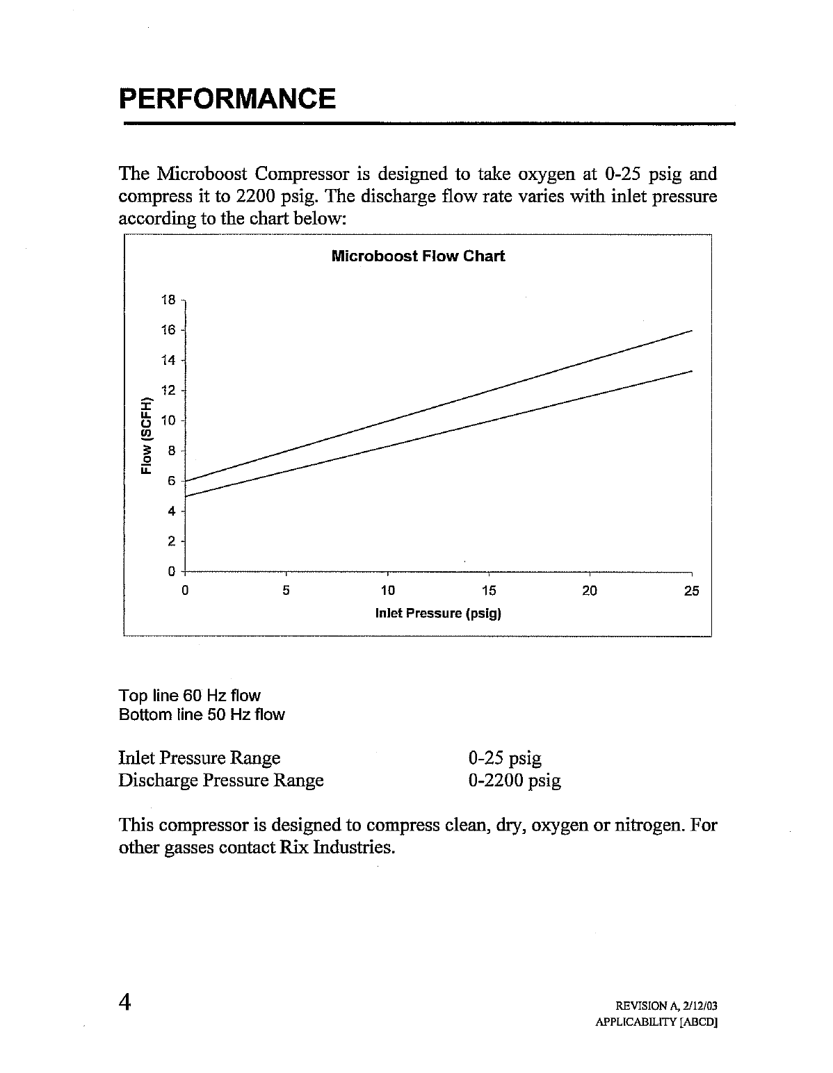
PERFORMANCE
The
Microboost
Compressor
is
designed
to
take
oxygen
at
0-25
psig
and
compress
it
to
2200
psig.
The
discharge
flow
rate
varies
with
inlet
pressure
according
to
the
chart
below:
Microboost
Flow
Chart
18
16
-
14
-
12-
10-
Flow
(SCFH)
0
' :
一
; ,
10 15
20
25
Inlet
Pressure
(psig)
o
a
Top
line
60
Hz
flow
Bottom
line
50
Hz
flow
Inlet
Pressure
Range
0-25
psig
Discharge
Pressure
Range
0-2200
psig
This
compressor
is
designed
to
compress
clean,
dry,
oxygen
or
nitrogen.
For
other
gasses
contact
Rix
Industries.
4
REVISION
A,
2/12/03
APPLICABILITY
[ABCD]
SAFETY
DANGER
Keep
away
from
live
circuits.
Do
not
attempt
to
replace
components
or
make
adjustments
unless
the
power
to
the
compressor
has
been
disconnected
and
all
pressure
relieved.
DANGER
Never
operate with
safety
devices
removed,
modified,
or
disabled.
This
includes
guards
for
moving
objects,
protection
from
high
temperatures
surfaces,
pressure
relief
valves,
or
covers
over
electrical
components.
Surfaces
on
the
motor
and
compressor
can
become
hot
and
may
cause
pain
or
discomfort
when
touched.
Allow
the
equipment
to
cool
before
handling
it.
ID
R
To
prevent
FIRE,
SERIOUS
INJURY,
and/or
DEATH,
it
is
the
User’s
responsibility
to
ensure
that
all
parts
used
in
the
compression
assembly
and
gas
plumbing
of
this
Rix
Oxygen
compressor
and
any
other
portions
of the
gas
stream
that
may
be
exposed
during
the
installation
of
new
or
replacement
parts
are
cleaned
for
Oxygen
Service
prior
to
installation.
Any
work
to
be
done
on
the
compressor
where
the
gas
stream
may
be
exposed
must
be
done
in
accordance
with
safe
Oxygen
Equipment
handling
procedures.
|
No
attempt
should
be
made
to
work
on
the
machine
without
full
knowledge
of
Oxygen
handling
equipment
handling
and
the
potential
hazards
of
contamination.
Factory
oxygen
cleaned
parts
are
denoted
by
an
“X”
prefix
at
the
beginning
of
the
part
number.
It
is
the
User’s
responsibility
to
maintain
the
cleanliness
of
factory
cleaned
parts
and
any
other
existing
portions
of
the
gas
stream
that
may
be
exposed
during
the
initial
installation,
start-up,
or
during
installation
of
replacement
parts.
Rix
Industries
recommends
the
customer
establish
a
procedure
for
working
with
oxygen
machinery.
Refer
to
Compressed
Gas
Association,
Inc.
publication
number
CGA
G-4.1,
Cleaning
Equipment
for
Oxygen
Service.
REVISED
2/24/03
i
5
APPLICABILITY
[ABCD]
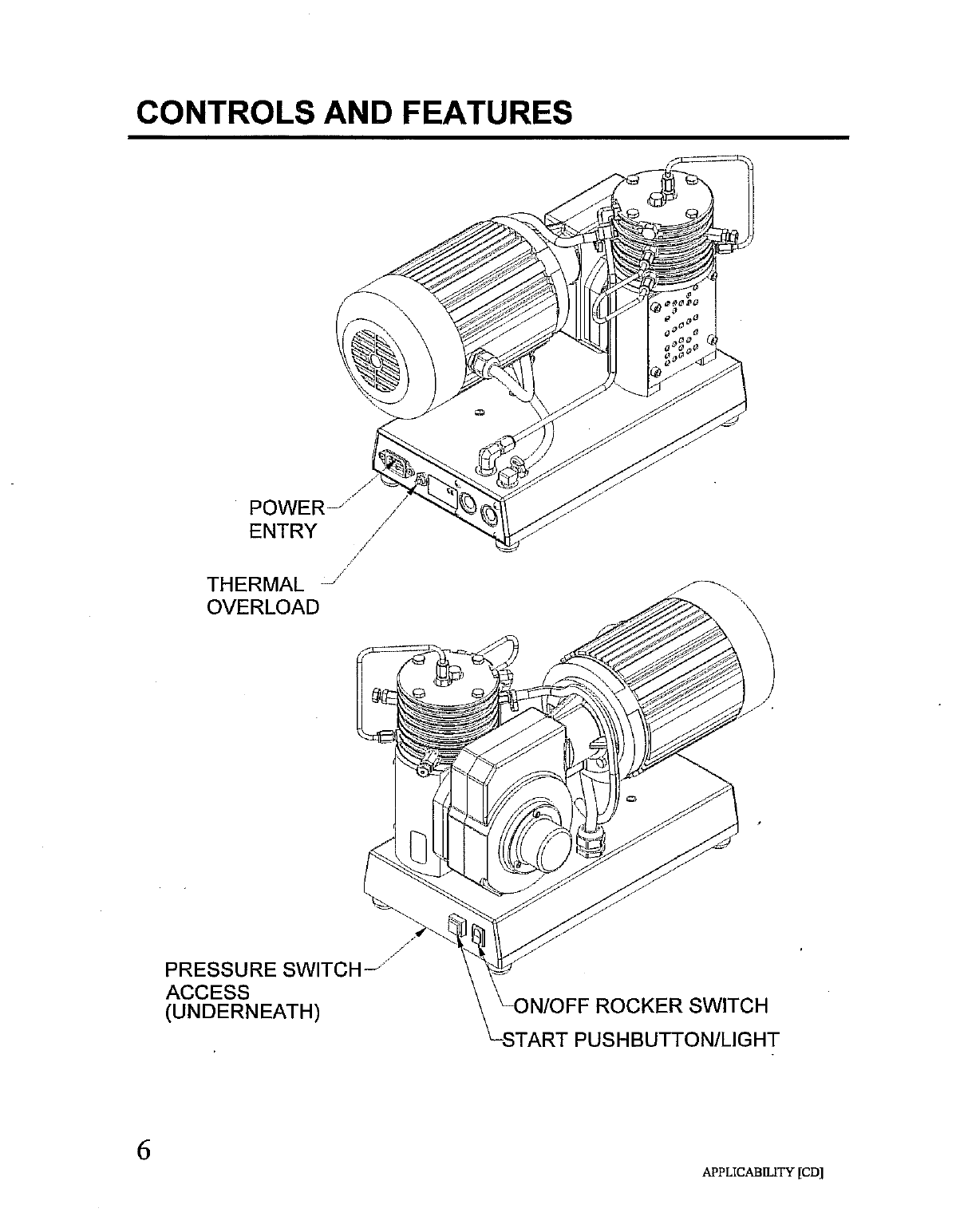
CONTROLS
AND
FEATURES
THERMAL
一
OVERLOAD
PRESSURE
SWITCH
(UNDERNEATH)
ON/OFF
ROCKER
SWITCH
START
PUSHBUTTON/LIGHT
APPLICABILITY
[CD]

CONTROLS
AND
FEATURES
Power
Entry
Medule-
The
Microboost
is
connected
to
a
source
of
power
using
a
power
cord
connected
to
the
Power
Entry
Module
(conforming
to
IEC-320-C13).
A
power
cord
suitable
for
the
intended
voltage,
115
VAC
or
230
VAC,
at
10
amps
should
be
used
to
connect
the
Microboost
to
the
source
of
power.
Overload-
The
pushbutton
reset
overload
is
provided
to
protect
the
equipment
if
the
motor
current
draw
exceeds
10
amps.
A
separate
automatic
reset
thermal
switch
is
located
inside
the
motor
to
protect
the
motor
from
overheating.
Power
On/Off
Rocker
Switch-
The
rocker switch
is
used
to
turn
power
on
to
the
Microboost
control
system.
This
switch
is
also
used
to
stop
the
unit
manually
when
it
is
running.
Start
Pushbutton-
The
momentary
lighted
pushbutton
is
provided
for
starting
the
compressor.
With
the
unit
plugged
into-a-seurce
of
electric
power
and
the
On/Off
rocker
switch
in
the
On
position
the
Start
Pushbutton
can
be
pressed
to
start
the
compressor
motor.
The
compressor
runs
until
the
pressure
switch
signals
it
to
stop
or
until
the
On/Off
rocker
switch
is
switched
Off.
Pressure
Switch-
The
pressure
switch
is
provided
to
automatically
stop
the
compressor
when
the
set
pressure
is
reached.
This-is-usuatty-factory
set
at
2200
psig.
The
switch
is
located
inside
the
Mitrotoost
tase
and
is
accessible
for
adjusting
through
a
rectangular
opening
provided
in
the
underside
cover.
Relief
Valves-
Relief
valves
are
provided
for
all
compression
stages.
The
first
stage
(set
at
359-psig)
and
second
stage-(set-at-1200-psig)
relief
valves
are
located
on
the
outside
of
the
compressor
as
shown.
The
third
stage
relief
valve
(set
at
2400
psig)
is
located—-inside—the
compressor
base.
These
prevent
pressures
from
rising
to
levels
that:
might
cause
damage.
REVISION
B,
2/12/03
7
APPLICABILITY
[ABCD]

INSTALLATION
13.2
DISCHARGE
CONNECTION
(1/4
NPT)
POWER
ENTRY
MODULE,
<
‚/АМЕЕТ
CONNECTION
(ANP)
APPLICABILITY
[CD]

INSTALLATION
The
Microboost
is
a
free
standing
package
weighing
61
lbs
and
is
meant
to
be
located
in
open
air
on
a
table,
shelf,
or
on
the
floor.
It
may
also
be
mounted
inside
a
frame
or
cabinet
as
long
as
sufficient
air
circulation
is
provided
to
prevent
overheating.
Locate
the
compressor
in
an
area
with
good
ventilation.
An
ambient
temperature
of
90°
F
or
less
is
preferable.
Circulating
air
across
the
compressor
with
an
external
fan will
make
it
operate
better
and
last
longer.
Rix
recommends
installing
a
flow
check
valve
after
the
Microboost
discharge
to
prevent
reverse
flow
when
the
compressor
is
off.
Pressure
gauges
should
be
installed
at
the
suction
and
discharge
to
help
in
monitoring
performance
and
for
troubleshooting.
Plug
into
a
source
of
power
that
is
protected
for
15
amps
(115
V)
or
10
amps
(230
V).
Connect
the
compressor
inlet
to
a
source
of
clean,
dry gas
regulated
not
to
exceed
25
psig.
Inlet
filtration
to
2
micron
max
particle
size
is
recommended.
Particle
contamination
can
cause
failure.
Connect
the
compressor
discharge
to
a
high
pressure
cylinder
or
manifold
designed
to
handle
pressures
at
2300
psig.
A
discharge
filter
of
at
least
5
micron
is
recommended
to
remove
seal
wear
(Teflon)
particles.
The
customer
is
responsible
for
designing
and
adequately
protecting
the
plumbing
and
equipment
he
attaches
to
the
Microboost.
Exposed
surfaces
of the
operating
motor
and
compressor
can
reach
180°
F
and
may
cause
pain
or
discomfort
if
touched.
Locate
the
unit
in
a
safe
location
where
it
is
protected
from
human
contact.
REVISION
B,
2/12/03
9
APPLICABILITY
[ABCD]
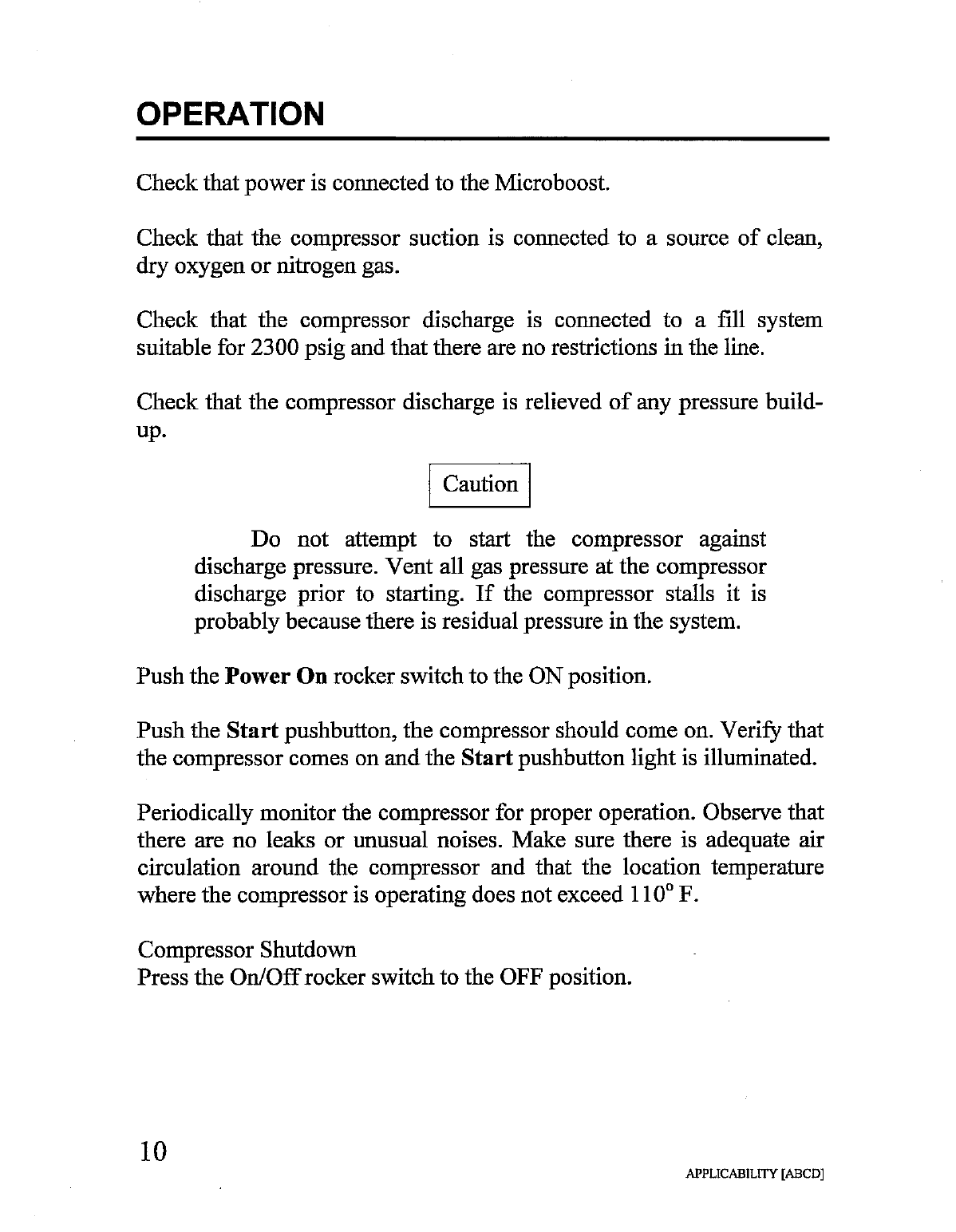
OPERATION
Check
that
power
is
connected
to
the
Microboost.
Check
that
the
compressor
suction
is
connected
to
a
source
of
clean,
dry
oxygen
or
nitrogen
gas.
Check
that
the
compressor
discharge
is
connected
to
a
fill
system
suitable
for
2300
psig
and
that
there
are
no
restrictions
in
the
line.
Check
that
the
compressor
discharge
is
relieved
of
any
pressure
build-
up.
Caution
Do
not
attempt
to
start
the
compressor
against
discharge
pressure.
Vent
all
gas
pressure
at
the
compressor
discharge
prior
to
starting.
If
the
compressor
stalls
it
is
probably
because
there
is
residual
pressure
in
the
system.
Push
the
Power
On
rocker
switch
to
the
ON
position.
Push
the
Start
pushbutton,
the
compressor
should
come
on.
Verify
that
the
compressor
comes
on
and
the
Start
pushbutton
light
is
illuminated.
Periodically
monitor
the
compressor
for
proper
operation.
Observe
that
there
are
no
leaks
or
unusual
noises.
Make
sure
there
is
adequate
air
circulation
around
the
compressor
and
that
the
location
temperature
where
the
compressor
is
operating
does
not
exceed
110°
F.
Compressor
Shutdown
Press
the
On/Off
rocker
switch
to
the
OFF
position.
10
APPLICABILITY
[ABCD]
SERVICING
Oxygen
compression
equipment
has
very
special
requirements
because
of
the
hazards
of
explosion
and
fire
associated
with
compressed
oxygen.
Rix
recommends
that
only
trained
and
qualified
personnel
work
on
this
equipment.
Rix
recommends
returning
the
compressor
to
Rix
or
to
an
approved
Rix
service
center
when
repairs
are
to
be
made.
Simple
operations
such
as
repairing
leaks
or
replacing
valves
or
relief
valves
may
be
done
locally
by
competent
mechanics
trained
in
working
on
oxygen
equipment.
Care
must
be
taken
when
handling
these
parts
so
that
surfaces
in
contact
with
oxygen
do
not
become
contaminated.
Changing
Suction
and
Discharge
Valves
(first
and
second
stages)
The
compression
valves
are
designed
into
the
tube
fittings
for
the
first
and
second
stages
suction
and
discharge.
These
valves
are
not
designed
to
be
serviceable
except
by
the
factory.
To
replace
a
valve,
remove
the
fitting
nut
and
tube
line
and
then
remove
the
valve.
When
reinstalling
a
valve
make
sure
that
the
O-ring
is
in
place
and
is
lightly
lubricated
with
oxygen
compatible
grease
such
as
KrytoxBo.
Valves
are
marked
with
an
‘S’
for
suction
and
a
‘D’
for
discharge.
Make
sure
the
proper
valve
is
used
when
reinstalling.
Do
not
interchange
suction
and
discharge
valves.
Reinstall
the
tube
line
and
tighten
the
nut
as
necessary
to
eliminate
leakage.
Use
a
soap
type
leak
test
fluid
to
check
for
leaks
while
the
compressor
is
running.
Tighten
just
enough
to
eliminate
all
leakage.
Caution
Do
not
over-tighten
as
this
may damage
the
sealing
surfaces
making
it
more
difficult
to
attain
a
leak-free
joint.
11
APPLICABILITY
[ABCD]
SERVICING
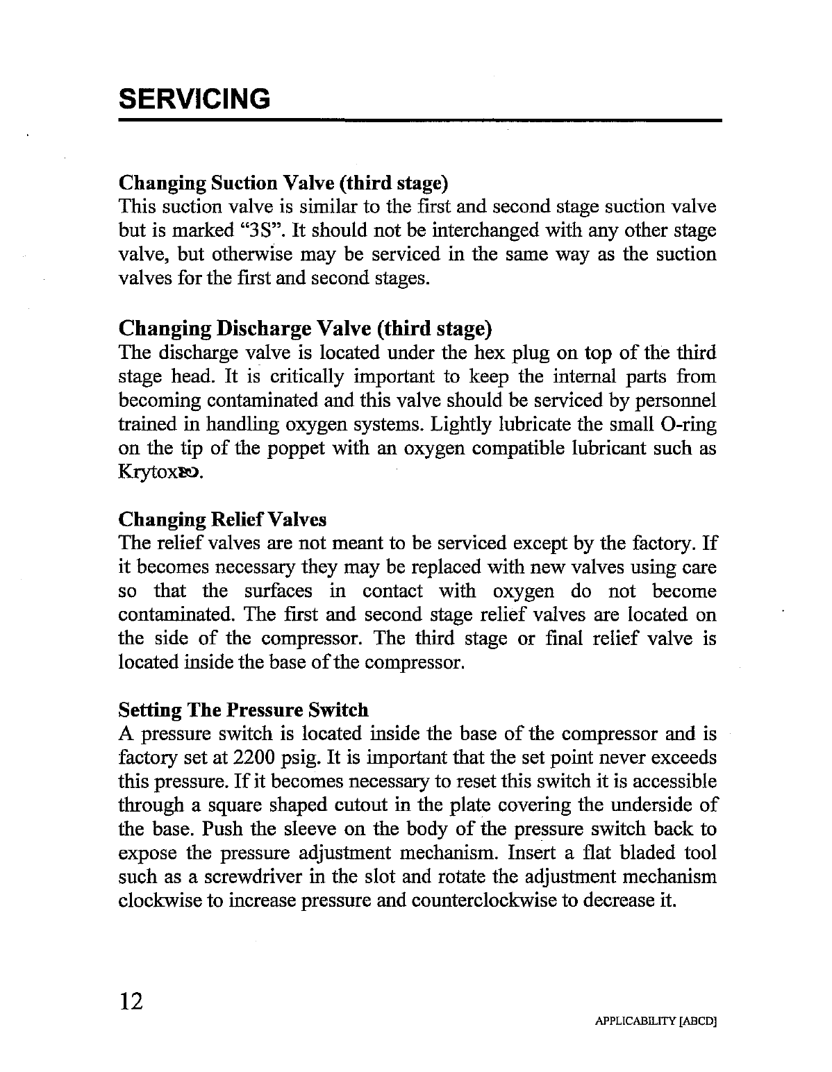
Changing
Suction
Valve
(third
stage)
This
suction
valve
is
similar
to
the
first
and
second
stage
suction
valve
but
is
marked
“3S”.
It
should
not
be
interchanged
with
any
other
stage
valve,
but
otherwise
may
be
serviced
in
the
same
way
as
the
suction
valves
for
the
first
and
second
stages.
Changing
Discharge
Valve
(third
stage)
The
discharge
valve
is
located
under
the
hex
plug
on
top
of
the
third
stage
head.
It
is
critically
important
to
keep
the
internal
parts
from
becoming
contaminated
and
this
valve
should
be
serviced
by
personnel
trained
in
handling
oxygen
systems.
Lightly
lubricate
the
small
O-ring
on
the
tip
of
the
poppet
with
an
oxygen
compatible
lubricant
such
as
Krytoxe.
Changing
Relief
Valves
The
relief
valves
are
not
meant
to
be
serviced
except
by
the
factory.
If
it
becomes
necessary
they
may
be
replaced
with
new
valves
using
care
so
that
the
surfaces
in
contact
with
oxygen
do
not
become
contaminated.
The
first
and
second
stage
relief
valves
are
located
on
the
side
of
the
compressor.
The
third
stage
or
final
relief
valve
is
located
inside
the
base
of
the
compressor.
Setting
The
Pressure Switch
A
pressure
switch
is
located
inside
the
base
of
the
compressor
and
is
factory
set
at
2200
psig.
It is
important
that
the
set
point
never
exceeds
this
pressure.
If
it
becomes
necessary
to
reset
this
switch
it
is
accessible
through
a
square
shaped
cutout
in
the
plate
covering
the
underside
of
the
base.
Push
the
sleeve
on
the
body
of
the
pressure
switch
back
to
expose
the
pressure
adjustment
mechanism.
Insert
a
flat
bladed
tool
such
as
a
screwdriver
in
the
slot
and
rotate
the
adjustment
mechanism
clockwise
to
increase
pressure
and
counterclockwise
to
decrease
it.
12
APPLICABILITY
[ABCD]

TROUBLESHOOTING
Circuit
breaker
in
Microboost
base
trips
Likely
causes:
1.
A
short
circuit
in
the
motor
or
electrical
wiring.
2.
A
bearing
is
failing
in
the
drive
system.
3.
A
problem
internal
to
the
compressor
or
gearbox
has
increased
the
motor
load.
Thermal
switch
in
motor
trips
(note:
this
will
reset
automatically)
Likely
causes:
1.
Inadequate
air
circulation
where
the
compressor
is
operating.
2.
Motor
current
draw
is
high
(see
overload
causes
listed
above).
Relief valves
leaks
or
relieves
Likely
causes:
1.
A
valve
problem
(either
suction
or
discharge)
in
the
next
higher
stage
of
compression.
2.
A
faulty
relief
valve
(damaged
seat
or
maladjustment).
Low
flow
Likely
causes:
1.
A
leak
in
a
tube
or
pipe
fitting
on
the
compressor.
2.
A
leaking
relief
valve.
3.
Worn
piston
seals
in
the
compressor.
Compressor
stalls
Likely
causes:
1.
Mechanical
failure
such
as
a
bearing
seizure.
Compressor
will
not
start
Likely
causes:
1.
The
compressor
pressure
is
above
the
pressure
switch
setting.
2.
The
motor
has
overheated
and
tripped
the
thermal
switch.
3.
The
circuit
breaker
tripped.
13
APPLICABILITY
[ABCD]

PARTS
BREAKDOWN
APPLICABILITY
[CD]
14

PARTS
BREAKDOWN
Compressor
Assembly
Major
Components
MICROBOOST
Model
MB-D-115
115
V,
50/60 Hz
ITEM
QTY
PART
NUMBER
DESCRIPTION
1
1
107-7309
MOTOR/GEARBOX
2
1
G100-MB-B
COMPRESSOR
(see
separate
parts
list,
page
17)
3
1
G200-MB-115-B
BASE
(see
separate
parts
list,
page
19)
4
1
138-5777
POWER
CORD
MICROBOOST
Model
MB-D-230
230
V,
50/60
Hz
ТЕМ
QTY
PART
NUMBER
DESCRIPTION
1
1
107-7309
MOTOR/GEARBOX
2
1
G100-MB-B
COMPRESSOR
(see
separate
parts
list,
page
17)
3
1
G200-MB-230-B
BASE
(see
separate
parts
list,
page
19)
4
1
МА
POWER
CORD
(provided
by
customer)
15
APPLICABILITY
[BCD]
PARTS
BREAKDOWN
16
X
NX
q
X
X
X
NOON
SON
ON
NOON
X
Sc
\
X
|
APPLICABILITY
[BCD]
X
a
o
ペー
ジ
\
\
VE
A
な
ο
一
À
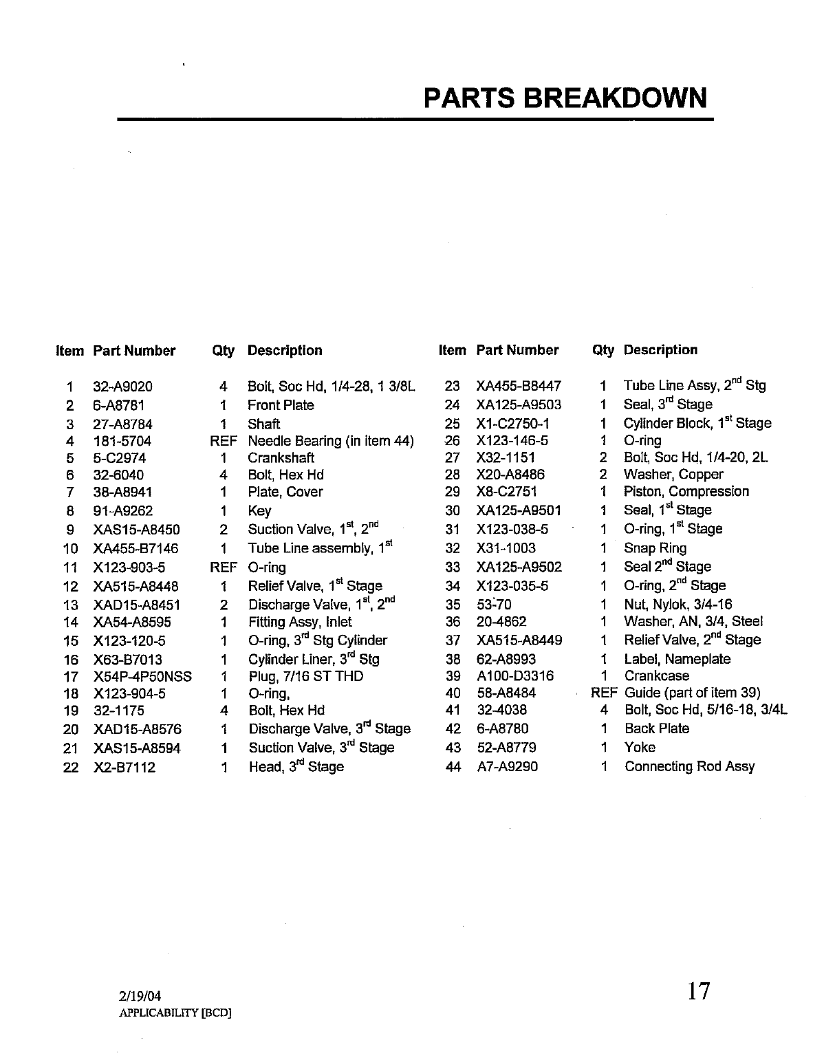
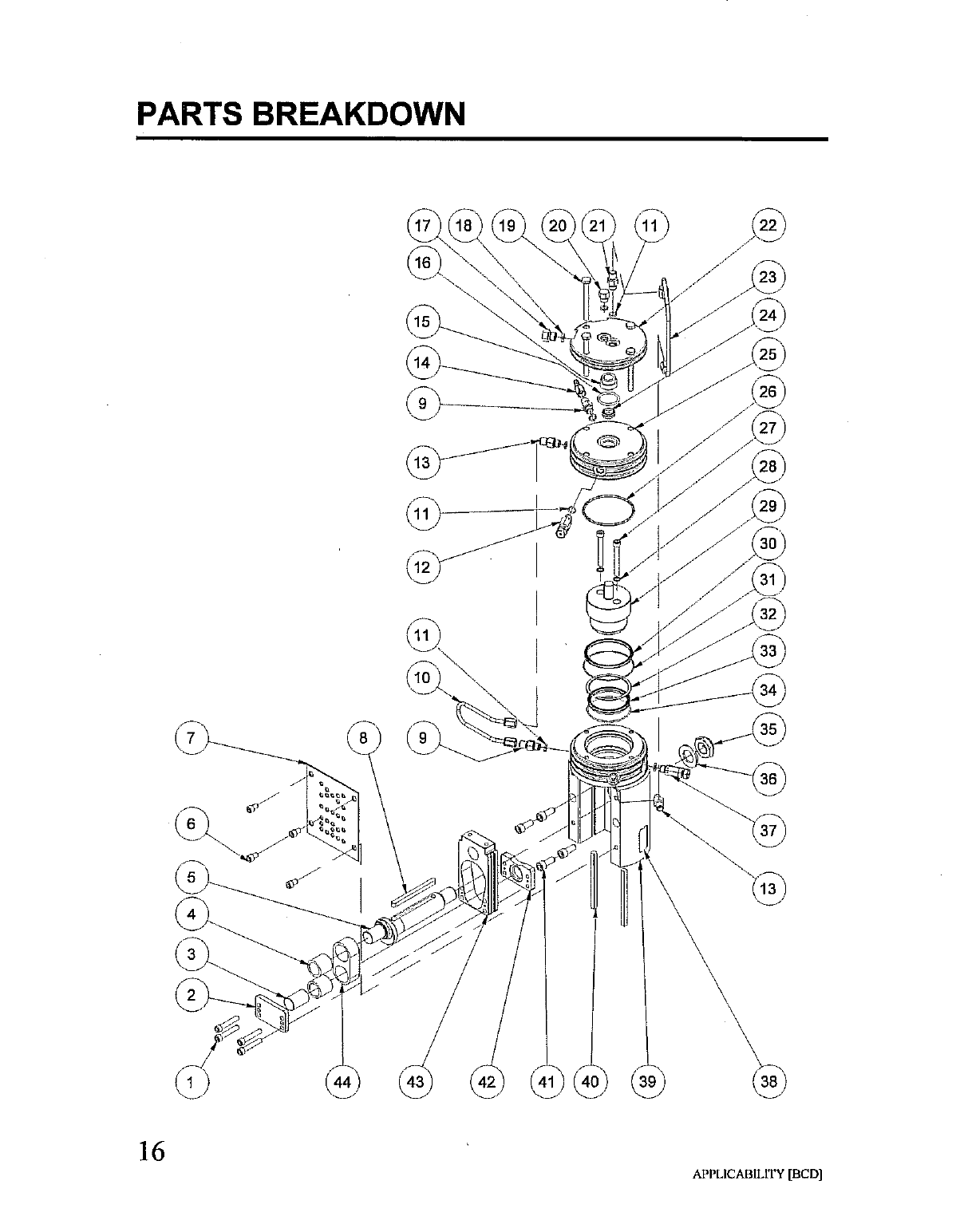
PARTS
BREAKDOWN
Item
Part
Number
On
AaAhwW
ND
=
NON
N
dad
SÅ
A
A
A
ーー
D
> © ©
©
JO
0
B w D = © ©
32-A9020
6-A8781
27-A8784
181-5704
5-C2974
32-6040
38-A8941
91-A9262
XAS15-A8450
XA455-B7146
X123-903-5
XA515-A8448
XAD15-A8451
XA54-A8595
X123-120-5
X63-B7013
X54P-4P50NSS
X123-904-5
32-1175
XAD15-A8576
XAS15-A8594
X2-B7112
2/19/04
Qty
Description
A
ода
Я
a
Ma-
Ti
n
APPLICABILITY
[BCD]
Bolt,
Soc
Hd,
1/4-28,
1
3/8L
Front
Plate
Shaft
Needle
Bearing
(in
item
44)
Crankshaft
Bolt,
Hex
Hd
Plate,
Cover
Key
Suction
Valve,
1%,
2%
Tube
Line
assembly,
1*
O-ring
Relief
Valve,
1°
Stage
Discharge
Valve,
1%,
2"
Fitting
Assy,
Inlet
O-ring,
3% Stg
Cylinder
Cylinder
Liner,
3"
Stg
Plug,
7/16
ST
THD
O-ring,
Bolt,
Hex
Hd
Discharge
Valve,
gi
Stage
Suction
Valve,
3"
Stage
Head,
3"
Stage
Item
Part
Number
23
24
25
26
27
28
29
30
31
32
33
34
35
36
37
38
39
40
41
42
43
44
XA455-B8447
XA125-A9503
X1-C2750-1
X123-146-5
X32-1151
X20-A8486
X8-C2751
XA125-A9501
X123-038-5
X31-1003
XA125-A9502
X123-035-5
53-70
20-4862
XA515-A8449
62-A8993
A100-D3316
58-A8484
32-4038
6-A8780
52-A8779
A7-A9290
Qty
4
4
1
1
2
2
1
4
1
1
1
1
1
1
1
1
1
REF
4
1
1
1
Description
Tube
Line
Assy,
2
Stg
Seal,
3%
Stage
Cylinder
Block,
1º
Stage
O-ring
Bolt,
Soc
Hd,
1/4-20,
2L
Washer,
Copper
Piston,
Compression
Seal,
1º
Stage
O-ring,
1°
Stage
Snap
Ring
Seal
2™
Stage
O-ring,
2" Stage
Nut,
Nylok,
3/4-16
Washer,
AN,
3/4,
Steel
Relief
Valve,
2"!
Stage
Label,
Nameplate
Crankcase
Guide
(part
of
item
39)
Bolt,
Soc
Hd,
5/16-18,
3/4L
Back
Plate
Yoke
Connecting
Rod
Assy
17
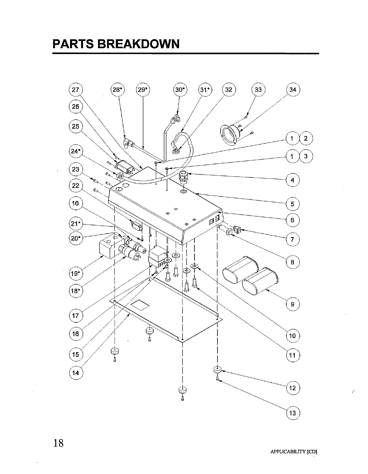
PARTS
BREAKDOWN
18
APPLICABILITY
[CD]
Other manuals for MB-115
1
This manual suits for next models
1
Table of contents
Other RIX Air Compressor manuals

Popular Air Compressor manuals by other brands


Clarke
Clarke RAIDER 15/1000 Operation & maintenance instructions

Oasis
Oasis YC4000 owner's manual

Campbell Hausfeld
Campbell Hausfeld CE3000 operating instructions

Ingersoll-Rand
Ingersoll-Rand P130WJDU Operating, Maintenance & Parts Manual

York
York VSD 270 Operation manual

KING
KING KC-5280V3-MS instruction manual