BENDIX SNA-01 Mounting instructions

1
All SNA-01 compressors are equipped with a safety
valve to protect the compressor head in the event of, for
example, a discharge line blockage downstream of the
compressor. Excessive air pressure will cause the safety
valve to unseat, release air pressure, and give an audible
alert to the operator. The safety valve is installed in the
safety valve port of the discharge jumper. The discharge
jumper's function is to relocate the discharge port such
that easy installation to the existing vehicle discharge line
is permitted. It also enhances discharge air cooling.
DESCRIPTION
The function of the air compressor is to provide and
maintain air under pressure to operate devices in air
brake systems. The Bendix®SNA-01™Compressor is
a single-cylinder reciprocating compressor with a rated
displacement of 15.8 cubic feet per minute at 1250 RPM.
The compressor consists of a water-cooled cylinder head
assembly and an integral air-cooled crankcase assembly.
The cylinder head assembly is made up of the cylinder
head, discharge jumper, cooling plate, and valve plate
assembly. It uses two sealing gaskets and two o-rings.
The cylinder head, discharge jumper and cooling plate
are made from aluminum. The cylinder head contains air
and water ports as well as an unloader assembly. The
discharge jumper is connected to the cylinder head and re-
routes the discharge air to the discharge port of the cylinder
head assembly. It assists in cooling the compressor. A
cooling plate is located between the cylinder head and
valve plate assemblies and also assists in cooling.
The valve plate assembly consists of brazed steel plates
which have valve openings and passages for air and
engine coolant to ow into and out of the cylinder head. The
compressor's discharge valves are part of the valve plate
assembly. The inlet reed valve/gasket is installed between
the valve plate assembly and the top of the crankcase.
The cast iron crankcase houses the piston assembly,
connecting rod, crankshaft, and related bearings.
®
SD-01-10142
BENDIX®SNA-01™COMPRESSOR
FIGURE 1 - BENDIX®SNA-01™COMPRESSOR
Safety
Valve
Valve Plate
Assembly
Crankcase
Cylinder
Head
Cooling
Plate
The Bendix®SNA-01™compressor is a service new
single cylinder compressor developed exclusively
for the following engines; Volvo®D11, D13 and D16;
and the Mack®MP7 and MP8 engines manufactured
from 2006 through 2010.
NOTE: A retrot kit is included with the compressor
and is intended to support the retrofit of this
compressor only on the engines and time frame
specied above.
Rear End
Cover
Crankshaft
Discharge Jumper
Inlet Fitting
Coolant Fitting

2
GENERAL SAFETY GUIDELINES
WARNING! PLEASE READ AND FOLLOW THESE INSTRUCTIONS
TO AVOID PERSONAL INJURY OR DEATH:
When working on or around a vehicle, the following guidelines should be observed AT ALL TIMES:
▲Park the vehicle on a level surface, apply the
parking brakes and always block the wheels.
Always wear personal protection equipment.
▲Stop the engine and remove the ignition key
when working under or around the vehicle.
When working in the engine compartment,
the engine should be shut off and the ignition
key should be removed. Where circumstances
require that the engine be in operation, EXTREME
CAUTION should be used to prevent personal
injury resulting from contact with moving,
rotating, leaking, heated or electrically-charged
components.
▲Do not attempt to install, remove, disassemble
or assemble a component until you have read,
and thoroughly understand, the recommended
procedures. Use only the proper tools and
observe all precautions pertaining to use of those
tools.
▲If the work is being performed on the vehicle’s
air brake system, or any auxiliary pressurized air
systems, make certain to drain the air pressure
from all reservoirs before beginning ANY work
on the vehicle. If the vehicle is equipped with a
Bendix®AD-IS®air dryer system, a Bendix®DRM™
dryer reservoir module, or a Bendix® AD-9si®air
dryer, be sure to drain the purge reservoir.
▲Following the vehicle manufacturer’s
recommended procedures, deactivate the
electrical system in a manner that safely removes
all electrical power from the vehicle.
▲Never exceed manufacturer’s recommended
pressures.
▲Never connect or disconnect a hose or line
containing pressure; it may whip and/or cause
hazardous airborne dust and dirt particles. Wear
eye protection. Slowly open connections with
care, and verify that no pressure is present. Never
remove a component or plug unless you are
certain all system pressure has been depleted.
▲Use only genuine Bendix®brand replacement
parts, components and kits. Replacement
hardware, tubing, hose, ttings, wiring, etc. must
be of equivalent size, type and strength as original
equipment and be designed speci cally for such
applications and systems.
▲Components with stripped threads or damaged
parts should be replaced rather than repaired.
Do not attempt repairs requiring machining or
welding unless speci cally stated and approved
by the vehicle and component manufacturer.
▲Prior to returning the vehicle to service, make
certain all components and systems are restored
to their proper operating condition.
▲For vehicles with Automatic Traction Control
(ATC), the ATC function must be disabled (ATC
indicator lamp should be ON) prior to performing
any vehicle maintenance where one or more
wheels on a drive axle are lifted off the ground
and moving.
▲The power MUST be temporarily disconnected
from the radar sensor whenever any tests USING
A DYNAMOMETER are conducted on a vehicle
equipped with a Bendix® Wingman®system.
▲You should consult the vehicle manufacturer's operating and service manuals, and any related literature,
in conjunction with the Guidelines above.

3
A nameplate; attached to the outboard side of the
crankcase; is stamped with information identifying the
Bendix piece number and serial number of the compressor.
See Figure 3.
FIGURE 2 - BENDIX®SNA-01™COMPRESSOR (CUT-AWAY)
FIGURE 3 - NAMEPLATE INFORMATION
Discharge Port
Valve Plate Assembly
Crankcase
Cylinder Head
Cooling Plate
Rear End Cover
Crankshaft
Discharge Jumper
Oil Supply Port
Piston Assembly
Special Fitting
(pre-installed in
coolant port)
Unloader Piston
Sleeve Bearing
Rear Cover Plate
Special Fitting
(pre-installed in
inlet port)
FIGURE 5 - CHARGING SYSTEM WITH BENDIX SNA-01
COMPRESSOR
Compressor
Supply Reservoir
Governor
Reservoir
Port
Governor
Unloader Port Air Dryer
FIGURE 4 - TYPICAL COMPRESSOR APPLICATIONS
2006–2010 Volvo®
D11, D13 & D16
Engines
2006–2010 Mack®
MP7 & MP8
Engines
PC.
NO.
Customer Model,
Customer Piece Number,
Bendix Piece Number
and Serial Number
shown here
PRODUCT OF BENDIX MFD. IN (COUNTRY)

4
OPERATION
The compressor is driven by the vehicle's engine and
functions continuously while the engine is in operation.
Actual compression of air is controlled by the compressor
unloading mechanism operating in conjunction with a
governor.
AIR INTAKE (LOADED)
Just as the piston begins the down stroke, (a position
known as Top Dead Center, or TDC), the vacuum created
in the cylinder bore above the piston causes the inlet reed
valve to ex open. Atmospheric air ows through the open
inlet valve and lls the cylinder bore above the piston. See
Figure 6.
AIR COMPRESSION (LOADED)
When the piston reaches the bottom of the stroke, (a
position known as Bottom Dead Center, or BDC), the inlet
reed valve closes. Air above the piston is trapped by the
closed inlet reed valve and is compressed as the piston
moves upwards. When air in the cylinder bore reaches
a pressure greater than that of the system pressure, the
discharge reed valves open and allow air to ow into the
discharge line and air brake system.
At the same time, air ows into the hollow center of the
unloader piston through an opening in the end of the piston.
Compressed air acts on the interior surfaces of the unloader
piston and
—
along with the unloader piston spring
—
holds
the unloader piston in the down position, against its seat
on the valve plate. See Figure 7.
FIGURE 7 - OPERATION - LOADED (COMPRESSION)
Piston Moving Up
Air Inlet
Port
Inlet
Valve
Closed
Air
Discharge
Port
Discharge
Valve
Open
Unloader
Piston
Down &
Seated
Valve
Plate
Unloader
Port
Cooling
Plate
FIGURE 6 - OPERATION - LOADED (INTAKE)
Piston Moving Down
Air Inlet
Port
Inlet
Valve
Open
Air
Discharge
Port
Discharge
Valve
Closed
Unloader
Piston
Down &
Seated
Valve
Plate
Unloader
Port
Cooling
Plate

5
NON COMPRESSION OF AIR (UNLOADED)
When air pressure in the supply reservoir reaches the
cut-out setting of the governor, the governor delivers
system air to the compressor unloader port. Air entering
the unloader port acts on the unloader piston causing
the piston to move away from its seat on the valve plate
assembly. When the unloader piston is unseated, an air
passageway is opened between the cylinder bore and a
secondary compartment
—
or “closed room”
—
in the interior
of the cylinder head.
As the piston moves from Bottom Dead Center (BDC)
to Top Dead Center (TDC) air in the cylinder bore ows
past the unseated unloader piston, into the “closed
room”. The size of the closed room is sufcient to accept
the compressed air provided by the compressor piston
without creating excessive air pressure in the “closed
room”. On the piston down stroke (TDC to BDC) air ows
in the reverse direction
—
from the “closed room” past the
unseated unloader piston and inlet reed valve
—
and into
the cylinder bore. Note: For optimum performance, it is
recommended that the air dryer installed in the system
be equipped with a “turbo cut-off” feature. See Figure 8.
LUBRICATION
The vehicle's engine provides a continuous supply of oil
to the compressor. Pressurized oil is routed from the
engine to the compressor's oil inlet port at the rear of the
crankcase. From there the oil ows through a passageway
on the inboard side of the crankcase to the front crankshaft
journal and sleeve bearing. An oil passage in the crankshaft
routes pressurized oil to the connecting rod journal and the
rear crankshaft journal. Spray lubrication of the cylinder
bores and connecting rod wrist pin bushings is obtained as
oil is forced out around the crankshaft journals by engine
oil pressure. Oil then falls to the bottom of the compressor
crankcase and is returned to the engine through drain holes
in the compressor mounting ange.
COOLING
Bendix®SNA-01™ compressors are cooled by air owing
through the engine compartment as it passes the
compressor's crankcase bore and by the ow of engine
coolant through the cylinder head. Coolant supplied by the
engine cooling system passes through connecting lines into
the cylinder head. It passes through internal passages in
the cylinder head, cooling plate, and valve plate assembly
and returns to the engine. Figure 9 illustrates the coolant
port locations and proper ow path. Proper cooling is
important in minimizing discharge air temperatures - see
the tabulated technical data in the compressor specication
section of this manual for specic requirements.
AIR INDUCTION
Bendix SNA-01 air compressors are only permitted to be
naturally aspirated
—
use of engine turbocharger as an air
source is not allowed. See Figure 5 for an example of a
naturally aspirated air induction system.
PREVENTIVE MAINTENANCE
Regularly scheduled maintenance is the single most
important factor in maintaining the air brake charging
system. Refer to Table A in the Troubleshooting section
of this manual, for a guide to various considerations that
must be given to maintenance of the compressor and other
related charging system components.
Important Note: Review the warranty policy before
performing any intrusive maintenance procedures. An
extended warranty may be voided if intrusive maintenance
is performed during this period.
FIGURE 8 - OPERATION - UNLOADED
Air From
Governor
Unloader
Port
Air above the piston shuttles back and forth
between the cylinder bore and the closed room
Unloader
Piston Up &
Unseated
Closed
Room

6
EVERY 6 MONTHS, 1800 OPERATING HOURS
OR AFTER EACH 50,000 MILES
—
WHICHEVER
OCCURS FIRST
—
PERFORM THE FOLLOWING
INSPECTIONS AND TESTS.
AIR INDUCTION
The Bendix®SNA-01™compressor is designed for
connection to the vacuum side of the engine’s air induction
system only.
A supply of clean air is one of the single most important
factors in compressor preventive maintenance. Since
the air supply for SNA-01 compressor and engine is the
engine air cleaner, periodic maintenance of the engine air
lter is necessary.
Inspect the compressor air induction system each time
engine air cleaner maintenance is performed.
1. Inspect the intake hose adapters for physical damage.
Make certain to check the adapters at both ends of the
intake hose or tubing.
2. Inspect the intake hose clamps and tighten them if
needed.
3. Inspect the intake hose or line for signs of drying,
cracking, chang and ruptures and replace if necessary.
4. Verify that the compressor inlet tting is tight (check
torque) and aligned properly to the hose. If kinks
exist, the tting should be loosened, realigned and
retightened.
5. Any metal tubes should also be tight (torqued properly)
to the mating tting. Inspect the metal tubes for any
cracks or breaks and replace if necessary.
COMPRESSOR COOLING
Inspect the compressor discharge port, inlet cavity, and
discharge line for evidence of restrictions and carbon
buildup. If more than 1/16" of carbon is found, thoroughly
clean or replace the affected parts. In some case, carbon
buildup indicates inadequate cooling. Closely inspect the
compressor cooling system. Check all compressor coolant
lines for kinks and restrictions to ow. Minimum coolant line
size is 3/8" Inside Diameter (I.D.) Check coolant lines for
internal clogging from rust scale. If coolant lines appear
suspicious, check the coolant ow and compare to the
tabulated technical data present in the back of this manual.
Carefully inspect the air induction system for restrictions.
LUBRICATION
Check the external oil supply line for kinks, bends, or
restrictions to ow. Supply lines must be a minimum of
3/16” I.D. Refer to the tabulated technical data in the back
of this manual for oil pressure minimum values.
Check the exterior of the compressor for the presence of
oil seepage and refer to the TROUBLESHOOTING section
for appropriate tests and corrective action.
OIL PASSING
All reciprocating compressors pass a minimal amount of
oil. Air dyers will remove the majority of oil before it can
enter the air brake system. For particularly oil sensitive
systems, the Bendix®PuraGuard®system can be used in
conjunction with a Bendix®air dryer.
If compressor oil passing is suspected, refer to the
TROUBLESHOOTING section (starting on page A-1) for
the symptoms and corrective action to be taken. In addition,
Bendix has developed the “Bendix Air System Inspection
Cup” (BASIC™) kit to help substantiate suspected excessive
oil passing. The steps to be followed when using the BASIC
kit are presented in APPENDIX B, on page A-16.
FIGURE 9 - BENDIX®SNA-01™COMPRESSOR CYLINDER
HEAD
Discharge
Jumper
Attach Bolt
(Qty. 4)
Discharge
Port
Inlet Port
(Fitting
Pre-Installed)
Unloader
Cover Coolant In
(Fitting
Pre-Installed)
Safety
Valve
Governor
Connection
Accessory Attach
Holes
M8x1.25 (2 Places)
Coolant Out
CYLINDER HEAD PORT IDENTIFICATION
The cylinder head connection ports are identied with
cast in numerals as follows:
0Air In
2Compressed Air Out
9Coolant In or Out
4Governor Control

7
COMPRESSOR DRIVE
Check for noisy compressor operation; which could indicate
excessive drive component wear. Adjust and/or replace
as necessary. Check all compressor mounting bolts and
retighten evenly if necessary. Check for leakage and
proper unloader mechanism operation. Repair or replace
parts as necessary.
COMPRESSOR UNLOADER & GOVERNOR
Test and inspect the compressor and governor unloader
system for proper operation and pressure setting.
1. Check for leakage at the unloader port. Replace leaking
or worn o-rings.
2. Make certain the unloader system lines are connected
as illustrated in Figure 5.
3. Cycle the compressor through the loaded and unloaded
cycle several times. Make certain that the governor
cuts-in (compressor resumes compressing air) at a
minimum of 105 psi (cut-out should be approximately
15–20 psi greater than cut-in pressure). Adjust or
replace the governor as required.
4. Note that the compressor cycles to the loaded and
unloaded conditions promptly. If prompt action is not
noted, repair or replace the governor and/or repair the
compressor unloader.
IMPORTANT NOTE
Replacement air governors must have a minimum cut-in
pressure of 100 psi. The cut-in pressure is the lowest
system pressure registered in the gauges before the
compressor resumes compressing air.
SERVICE TESTS
GENERAL
The following compressor operating and leakage tests
need not be performed on a regular basis. These tests
should be performed: a) when it is suspected that leakage
is substantially affecting compressor buildup performance;
or b) when it is suspected that the compressor is “cycling”
between the loaded (pumping) and unloaded (non-
pumping) modes due to unloader leakage.
IN SERVICE OPERATING TESTS
Compressor Performance: Build-up Test
This test is performed with the vehicle parked and the
engine operating at maximum recommended governed
speed. Fully charge the air system to governor cut-out (air
dryer purges). Pump the service brake pedal to lower the
system air pressure below 80 psi using the dash gauges.
As the air pressure builds back up, measure the time from
when the dash gauge passes 85 psi to the time it passes
100 psi. The time should not exceed 40 seconds. If the
vehicle exceeds 40 seconds, test for (and x) any air leaks,
and then re- test the compressor performance. If the vehicle
does not pass the test the second time, use the Advanced
Troubleshooting Guide for Air Brake Compressors, starting
on page A-1 of this document to assist your investigation
of the cause(s).
Note: All new vehicles are certied using the FMVSS 121 test
(paragraph S5.1.1) by the vehicle manufacturer, however
this test is a useful guide for in-service vehicles.
Optional Comparative Performance Check
It may be useful to also conduct the previous test with
the engine running at high idle (instead of maximum
governed speed), and record the time taken to raise the
system pressure a selected range (for example, from 90
to 120 psi, or from 100 to 120 psi, etc.) and record it in the
vehicle’s maintenance les. Subsequent build-up times
throughout the vehicle’s service life can then be compared
to the rst one recorded. (Note: the 40 second guide in
the test above does not apply to this build-up time.) If the
performance degrades signicantly over time, you may
use the Advanced Troubleshooting Guide for Air Brake
Compressors, starting on page A-1 of this document, to
assist investigation of the cause(s).
Note: When comparing build-up times, be sure to make
an allowance for any air system modications which would
cause longer times, such as adding air components or
reservoirs. Always check for air system leakage.

8
Inlet Fitting
FIGURE 10 - BENDIX®SNA-01™COMPRESSOR EXPLODED VIEW.
Cooling Plate
Unloader Cover
Unloader Cover Cap Screws
Unloader Piston
Unloader Balance Piston
O-Ring
Unloader Cover Gasket
Balance Piston Spring
Head Bolts
(includes washers)
O-Ring
O-Ring
Crankcase Alignment Pins
Alignment
Bushings
Crankcase
Cover
Crankcase
Bottom Cover
Gasket
Cap Screws
Plug
Sleeve Bearing
Plug
Inlet Reed Valve/
Gasket
Head Gasket
Cylinder Head
Valve Plate
Assembly
Piston Assembly
Safety Valve
Plug
Discharge Jumper Washer
Discharge Jumper
Discharge Jumper O-Ring
Discharge Jumper Plug
Top Coolant Fitting
Discharge Jumper Screw
O-Ring
Rear Cover
Plate
Rear End
Cover
Crankshaft
Cap Screw
Lockwasher
Cap Screw
Rear Cover
Plate Gasket
Connecting Rod
22
1
38
7
36
23
41
35
39
32
5
31
37
9
11
14
8
40
10
2
4
34
21
12
3
33
6
25
13
29
30
15
27
26
16
20
19
17
28
24
18
42
43

9
Component Identication
Item Quantity Description
1 6 Head Bolts
2 2 Unloader Cover Screw
3 1 Plug
4 1 Unloader Cover
5 1 Unloader Cover Gasket
6 1 Unloader Balance Piston
7 1 O-Ring
8 1 Balance Piston Spring
9 1 O-Ring
10 1 Unloader Piston
11 1 O-Ring
12 1 Bendix®ST-4™Safety Valve
13 1 Cylinder Head
14 2 Head Gasket
15 1 Cooling Plate
16 1 Valve Plate Assembly
17 1 Inlet Reed Valve Gasket
18 1 Piston Assembly
19 1 Connecting Rod
20 1 Sleeve Bearing
21 1 Crankcase
22 1 Crankshaft
23 2 Alignment Bushings
24 1 O-Ring
25 1 Rear End Cover
26 4 Cap Screw
27 1 Bottom Cover Gasket
28 1 Crankcase Cover
29 4 Cap Screws
30 1 Rear Cover Plate Gasket
31 2 Crankcase Alignment Pins
32 1 Rear Cover Plate
33 2 Cap Screw
34 2 Lockwasher
35 1 Inlet Fitting
36 1 Top Coolant Fitting
37 1 Discharge Jumper
38 4 Discharge Jumper Screw
39 4 Discharge Jumper Washer
40 2 Discharge Jumper O-Ring
41 1 Discharge Jumper Plug
42 1 Plug
43 1 Plug
Maintenance Kits and Service Parts
Item Quantity Description
Cylinder Head Gasket Kit P/N K023764
14 2 Head Gasket
17 1 Inlet Reed Valve Gasket
Discharge Jumper Kit P/N K092848
12 1 Bendix ST-4 Safety Valve
37 1 Discharge Jumper
38 4 Discharge Jumper Screw
39 4 Discharge Jumper Washer
40 2 Discharge Jumper O-Ring
41 1 Discharge Jumper Plug
Safety Valve P/N K035675
12 1 Bendix®ST-4™Safety Valve
Seal Kit P/N K115315
24 1 O-Ring
27 1 Bottom Cover Gasket
30 1 Rear Cover Plate Gasket
40 2 Discharge Jumper O-Ring
Special Fittings Kit P/N K115314
35 1 Inlet Fitting
36 1 Coolant Fitting
Unloader Kit P/N K109119
2 2 Unloader Cover Screw
5 1 Unloader Cover Gasket
6 1 Unloader Balance Piston
7 1 O-Ring
8 1 Balance Piston Spring
9 1 O-Ring
10 1 Unloader Piston
11 1 O-Ring
N/A 1 Grease Pack
Installation Kit P/N K092868
N/A 1 Inlet Hose
N/A 1 Coolant Hose
N/A 1 Coolant Fitting (Union)
N/A 3 Hose Clamp (Coolant)
N/A 3 Hose Clamp (Inlet)
N/A 1 Synex®Tubing
N/A 1 Unloader Line Fitting (Union)
Volvo®P/N 992065
N/A 1 Front Flange O-Ring (see note 1)
Volvo P/N 977650
N/A 1 Oil Supply Line (see notes 1 & 2)
1. Available from Volvo®distributor or dealer only.
2. Required to retrot the Bendix®SNA-01™compressor on a Mack®
MP7 or MP8 engine.

10
LEAKAGE TESTS
See the standard Air Brake System and Accessory Leakage
test on Page A-14 (Test 2).
Note: Leakage in the air supply system (components
before the supply reservoir - such as the governor, air dryer,
reservoir drain cocks, safety valve, and check valves) will
not be registered on the vehicle dash gauges and must
be tested separately. Refer to the various maintenance
manuals for individual component leakage tests and the
Bendix “Test and Checklist” published in the Air Brake
System Handbook (BW5057) and on the back of the Dual
Circuit Brake System Troubleshooting Card (BW1396).
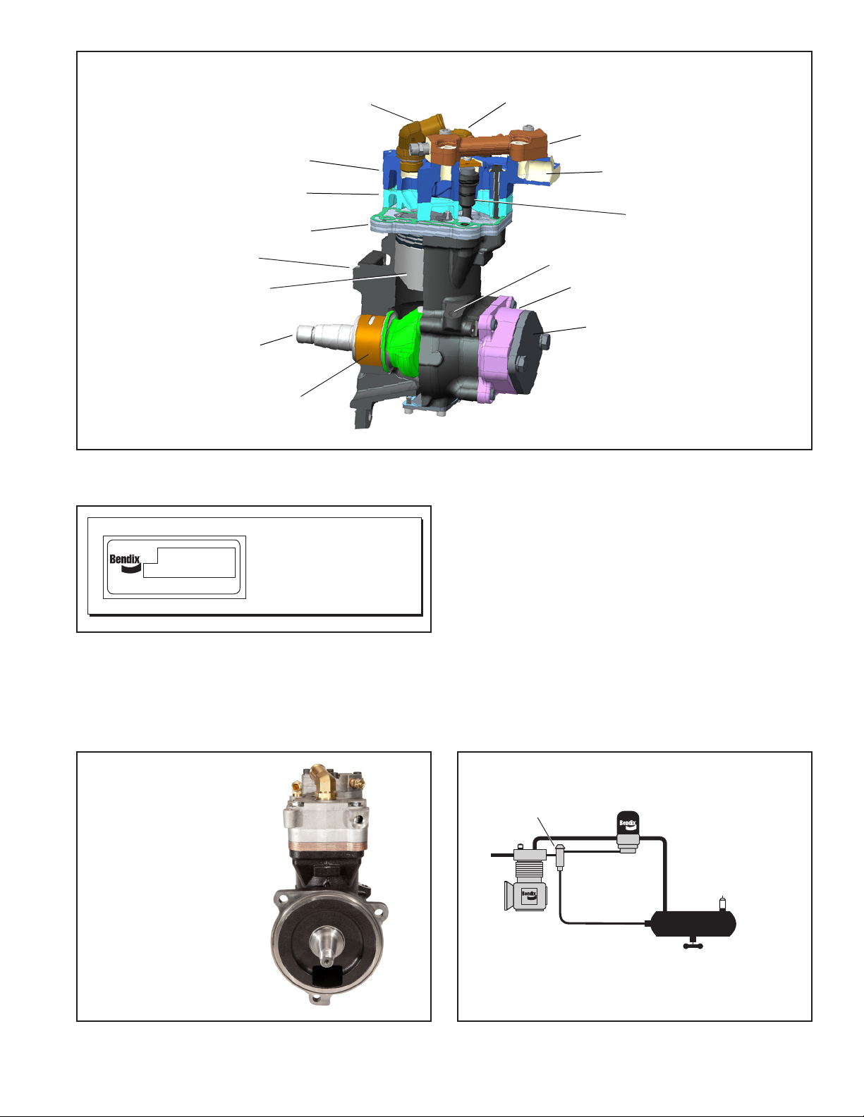
CYLINDER HEAD
Check for cylinder head gasket air leakage.
1. With the engine running, lower the air system pressure
to 60 psi and apply a soap solution around the cylinder
head. Check the gasket between the cylinder head
and valve plate assembly, the inlet reed valve/gasket
between the valve plate assembly and crankcase and
between the cylinder head and discharge jumper for
air leakage.
2. No leakage is permitted. If leakage is detected, replace
the compressor or repair the cylinder head using a
genuine Bendix®maintenance kit available from an
authorized Bendix®parts outlet.
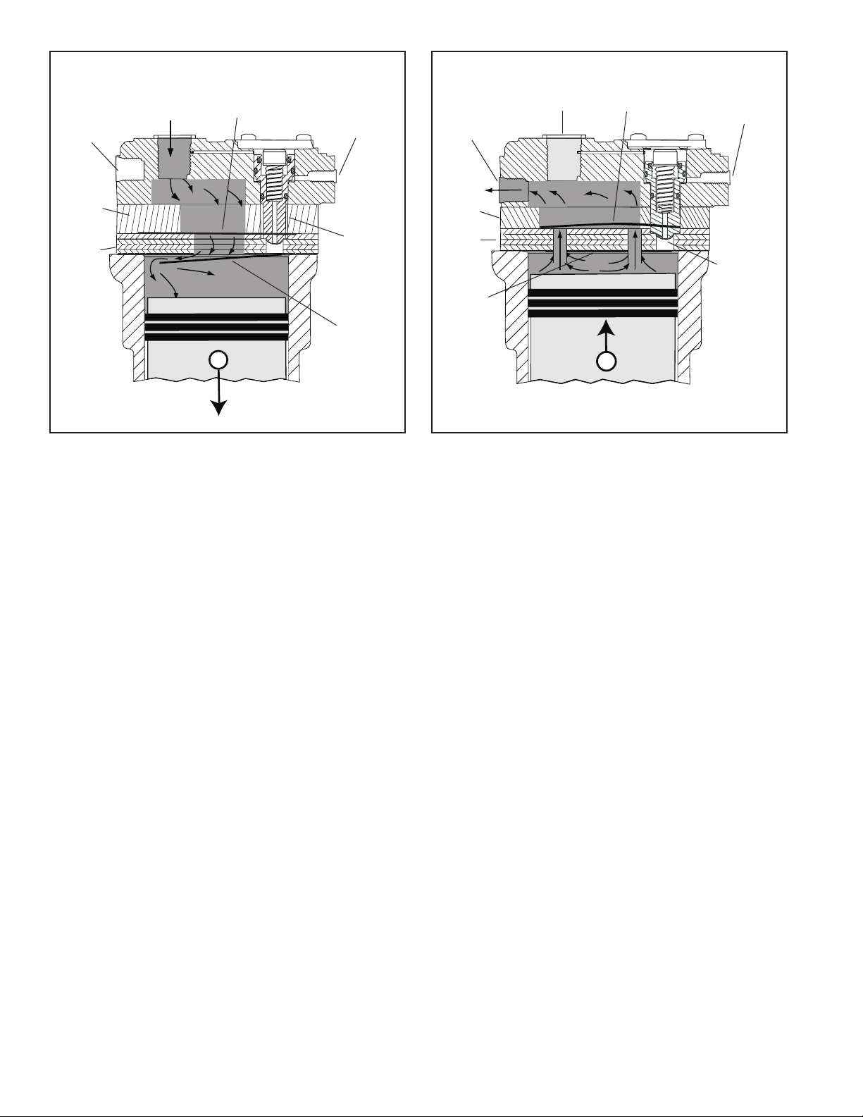
INLET, DISCHARGE & UNLOADER
In order to test the inlet and discharge valves and the
unloader piston, it is necessary to have shop air pressure
and an assortment of ttings. A soap solution is also
required.
1. With the engine shut off, drain ALL air pressure from
the vehicle.
2. Disconnect the inlet and discharge lines and remove
the governor or its line or adapter tting.
3. Apply 120 to 130 psi shop air pressure to the unloader
port and soap the inlet port. Leakage at the inlet port
should not exceed 50 sccm.
4. Apply 120 to 130 psi shop air pressure to the discharge
port and then apply and release air pressure to the inlet
port. Soap the inlet port and note that leakage at the
inlet port does not exceed 20 sccm.
If excessive leakage is noted in Tests 3 or 4, replace or
repair the compressor using genuine Bendix replacements
or maintenance kits available from any authorized Bendix
parts outlet.
While it is possible to test for inlet, discharge, and unloader
piston leakage, it may not be practical to do so. Inlet and
discharge valve leakage can generally be detected by
longer compressor build-up and recovery times. Compare
current compressor build-up times with the last several
recorded times. Make certain to test for air system
leakage
—
as described in the Service Operating Tests
section of this manual
—
before making a determination
that performance has been lost.
Unloader leakage is generally exhibited by excessive
compressor cycling between the loaded and unloaded
condition.
1. With service and supply system leakage below the
maximum allowable limits and the vehicle parked,
bring system pressure to governor cut-out and allow
the engine to idle.
2. The compressor should remain unloaded for a minimum
of 5 to 10 minutes. If the compressor cycling occurs
more frequently and service and supply system leakage
is within tolerance, replace the compressor or repair the
compressor unloader system using a genuine Bendix
maintenance kit available from authorized Bendix parts
outlets.
COMPRESSOR REMOVAL & DISASSEMBLY
GENERAL
The following disassembly and assembly procedure is
presented for reference purposes and presupposes that
a rebuild or repair of the compressor is being undertaken.
Several maintenance kits and service parts are available.
The instructions provided with these parts and kits should
be followed in lieu of the instructions presented here. See
the Maintenance and Service Parts section in this manual.
REMOVAL
In many instances it may not be necessary to remove the
compressor from the vehicle when installing the various
maintenance kits and service parts. The maintenance
technician must assess the installation and determine the
correct course of action.
These instructions are general and are intended to be
a guide. In some cases additional preparations and
precautions are necessary. In all cases follow the
instructions contained in the vehicle maintenance manual
in lieu of the instructions, precautions and procedures
presented in this manual.
1. Block the wheels of the vehicle and drain the air
pressure from all the reservoirs in the system.
2. Drain the engine cooling system and the cylinder head
of the compressor. Identify and disconnect all air, water
and oil lines leading to the compressor.

11
3. Remove as much road dirt and grease from the exterior
of the compressor as possible.
4. Remove the discharge and inlet ttings, if applicable,
and note their position on the compressor to aid in
reassembly.
Note: If a cylinder head maintenance kit is being
installed, stop here and proceed to PREPARATION FOR
DISASSEMBLY. If replacing the compressor continue.
5. Remove any supporting bracketing attached to the
compressor and note their positions on the compressor
to aid in reassembly.
6. Remove the front flange mounting bolts/nuts and
remove the compressor from the vehicle.
7. Inspect the drive gear and associated drive parts for
visible wear or damage. If the compressor drive gear
is worn or damaged, the drive gear must be removed
and replaced. Refer the Engine Manufacturer's service
manual to address the associated engine drive parts.
8. If the compressor is being replaced, stop here and
proceed to “Installing the Compressor” at the end
of the assembly procedure. (Note: Replacement
compressors do not come with the drive gear pre-
assembled on the compressor. If the drive gear is in
good condition, the drive gear and attachment nut can
be removed from the old compressor and transferred
to the new compressor or a new drive gear must be
purchased through a Volvo®distributor and installed on
the compressor.
PREPARATION FOR DISASSEMBLY
Remove the balance of road dirt and grease from the
exterior of the compressor with a cleaning solvent. If a rear
end cover or end cover adapter is used on the compressor
being worked on, mark it in relation to the crankcase. It is
recommended, but not specically necessary, to mark the
relationships of the cylinder head (13), cooling plate (15),
valve plate assembly (16), and crankcase (21).
A convenient method to indicate the above relationships
is to use a metal scribe to mark the parts with numbers or
lines. Do not use marking methods such as chalk that can
be wiped off or obliterated during rebuilding.
Prior to disassembly make certain that the appropriate kits
and/or replacement parts are available. Refer to Figure 10
during the entire disassembly and assembly procedure.
What follows is a description of a complete disassembly,
actual maintenance may only need to include portions of
these instructions.
DISCHARGE JUMPER ASSEMBLY & FITTINGS
Note: The discharge jumper (37) must be removed in order
to remove the inlet tting (35) and to service the unloader
mechanism.
1. Loosen and remove the four discharge jumper washers
(39) and discharge jumper screws (38) that secure
the discharge jumper (37) to the cylinder head (13).
Remove the discharge jumper (37) and the two o-rings
(40). Loosen and remove the safety valve (12) from the
discharge jumper (37), if necessary.
2. The inlet tting (35) and top coolant tting (36) were
pre-installed on the compressor by Bendix to ensure
proper positioning when the coolant and air induction
lines are installed. Unless the inlet tting (35) and top
coolant tting (36) have been damaged they should
stay intact. If it is necessary to remove the ttings, rst
loosen the jam nut of the inlet tting (35) and remove it
from the cylinder head (13). Then, loosen and remove
the top coolant tting (36) from the cylinder head (13).
CYLINDER HEAD ASSEMBLY
3. To restrain the spring force exerted by balance piston
spring (8) of the unloader assembly, hold the unloader
cover (4) in place while removing the two unloader
cover cap screws (2). Carefully release the hold on the
unloader cover until the spring force is relaxed, then
remove the unloader cover.
4. Remove the unloader cover gasket (5).
5. Remove the unloader balance piston (6), its spring
(8) and the unloader piston (10) along with its o-rings
(7, 9 & 11) from the cylinder head (13).
6. Remove the six head bolts (1) from the cylinder head
(13).
Note: The ve head bolts located towards the perimeter
of the cylinder head retain the cylinder head directly
to the crankcase. The single head bolt in the center
of the cylinder head holds the cylinder head, cooling
plate and valve plate assembly together; independent
of the crankcase.
7. Gently tap the cylinder head, cooling plate (15) and
valve plate assembly (16) with a soft mallet to break
the gasket seal between the valve plate assembly and
the crankcase (21). Lift the cylinder head with cooling
plate and valve plate assembly off the crankcase.
8. Remove the metal inlet reed valve/gasket (17).
9. Gently tap the cylinder head, cooling plate and valve
plate assembly with a soft mallet to break the gasket
seals. Then separate the cylinder head from the cooling
plate (15) and valve plate assembly and remove the
two gaskets (14) between them.

12
CRANKCASE COVER
1. Remove the four crankcase cover cap screws (29)
securing the crankcase cover (28) to the crankcase
(21). Using a soft mallet, gently tap the crankcase cover
to break the gasket seal. Remove the crankcase cover
gasket (27).
REAR END COVER & COVER PLATE ASSEMBLY
NOTE: Mark position of the rear end cover. It should be
re-installed in the same orientation.
1. Remove the two cap screws (33) and lock washers (34)
from the rear end cover (25).
2. Remove the rear cover plate (32) and rear cover plate
gasket (30).
3. Remove the four end cover cap screws (26) that secure
the rear end cover to the crankcase.
4. Remove the rear end cover (25) from the crankcase.
5. Remove the o-ring seal (24) from the rear end cover
(25).
CLEANING OF PARTS GENERAL
All parts should be cleaned in a good commercial grade of
solvent and dried prior to inspection.
CYLINDER HEAD ASSEMBLY
1. Carefully remove all gasket material adhering to the
cylinder head (13), cooling plate (15), valve plate
assembly (16) and cast iron crankcase (21). Make
certain not to scratch or mar the gasket surfaces. Pay
particular attention to the gasket surfaces of the head.
2. Remove carbon deposits from the discharge and inlet
plate assembly. They must be open and clear in both
assemblies. Make certain not to damage the head.
3. Remove rust and scale from the cooling cavities and
passages in the cylinder head, cooling plate and valve
plate assembly and use shop air to clear debris from
the passages.
4. Check the threads in all cylinder head ports for
galling (e.g. abrasion, chang). Minor thread chasing
(damage) is permitted.
INSPECTION OF PARTS
CYLINDER HEAD, COOLING PLATE, VALVE
PLATE ASSEMBLY AND UNLOADER MECHANISM
1. Carefully inspect the head gasket surfaces on the
cylinder head (13) for deep gouges and nicks. Also,
inspect the cylinder head for any cracks or port thread
damage. If detected, the compressor must be replaced.
If large amounts of carbon build-up are present in the
discharge cavity such that it restricts the air ow through
the cylinder head, the compressor should be replaced.
2. Carefully inspect both sides of the head gasket surfaces
on the cooling plate (15) for deep gouges and nicks.
Also, inspect the cooling plate for any cracks or other
damage. If found, the compressor must be replaced.
3. Carefully inspect the valve plate assembly (16) gasket
surfaces (both sides) for deep gouges and nicks. Pay
particular attention to the gasket surface. An inlet
reed valve/gasket (17) is used between the valve
plate assembly and crankcase. This gasket surface
must be smooth and free of all but the most minor
scratches. If excessive marring or gouging is detected,
the compressor must be replaced. If large amounts of
carbon build-up are present on the two main surfaces, in
the two discharge valve holes or between the discharge
valve and the discharge seat, the compressor should
be replaced.
4. If the unloader assembly has been removed from the
cylinder head, the unloader assembly must be serviced
using the unloader kit. See the Maintenance and
Service Parts listing in this manual for kit contents and
part numbers.
5. If large amounts of carbon build-up are present on the
unloader piston (10) seat or orice or if the return spring
exhibits compression set, the unloader components
must be replaced with an unloader kit.
REAR COVER PLATE
Inspect the surface in direct contact with the gasket and
rear end cover plate (32). Remove any remaining gasket
material from the surface. There should be no gouges in
the surface directly in contact with the gasket.
If the rear cover plate (32) has been removed, it must
be serviced with the seal kit. See the Maintenance and
Service Parts listing in this manual for kit contents and
part numbers.
REAR END COVER
Check for cracks and external damage. Check the
crankshaft rear journal diameter for excessive wear, at
spots or galling. Check the cover plate threaded mounting
holes for thread damage. Minor thread chasing is permitted
but do not re-cut the threads. Carefully inspect the gasket
surface on the back of the rear end cover (25). (Note: This is
the surface the rear cover plate is in contact with). Remove
any remaining gasket material on the surface. This gasket
surface must be smooth and free of all but the most minor
scratches. If excessive marring or gouging is detected, the
compressor must be replaced.

13
DISCHARGE JUMPER ASSEMBLY
Inspect the o-ring grooves on the discharge jumper (37)
for damage. Inspect the air passageways of the discharge
jumper for excessive carbon which would restrict the air
ow from the compressor. If the carbon build-up exceeds
1/16” in any of the passageways, the discharge jumper
must be replaced with its service kit. See the Maintenance
and Service Parts listing in this manual for kit contents and
part numbers.
Inspect the safety valve (12). If there are signs that the
safety valve was “popping off”, it should be replaced with
the safety valve kit. See the Maintenance and Service Parts
listing in this manual for kit contents and part numbers.
CRANKCASE
Check the cylinder head gasket surface on the deck (top)
of the crankcase (21) for nicks, gouges, and marring.
A metal gasket is used to seal the cylinder head to the
crankcase. This surface must be smooth and free of all but
the most minor scratching. If excessive marring or gouging
is detected, the compressor must be replaced.
ASSEMBLY
General Note: All torques specied in this manual are
assembly torques and typically can be expected to fall off
after assembly is accomplished. Do not re-torque after
initial assembly torques fall unless instructed otherwise. A
compiled listing of torque specications is presented later
in this manual.
INCH POUNDS TO FOOT POUNDS
To convert inch pounds (in-lbs) to foot pounds (ft-lbs) of
torque, divide inch pounds by 12.
Example: 12 Inch Pounds = 1 Foot Pound
12
FOOT POUNDS TO INCH POUNDS
To convert foot pounds (ft-lbs) to inch pounds (in-lbs) of
torque, multiply foot pounds by 12.
Example: 1 Foot Pound x 12 = 12 Inch Pounds
REAR END COVER
1. Install the o-ring (24) on the rear end cover (25).
2. Orient the rear end cover (25) to the crankcase (21)
using the reference marks made during disassembly.
Carefully install the rear end cover on the crankcase
making certain not to damage the crankshaft bearing
surface. Note: The rear end cover should be fully seated
against the crankcase at this point.
3. Install the four end cover cap screws (26). “Snug” the
screws then tighten to 195–213 in-lbs (22-24 N•m)
using a crossing pattern.
REAR COVER PLATE
1. Place the rear cover plate gasket (30) onto the rear
cover plate (32). Note: This should be the same surface
that the old gasket was removed from.
2. Place the gasketed side of the cover plate (32) against
the rear end cover (25) making sure to line up the two
bolt holes.
3. Install the two cap screws (33) and lock washers (34)
into the threaded holes of the end cover and hand
tighten both cap screws.
4. Torque the two cap screws (33) to 239–292 in-lbs (27-
33 N•m) to secure the rear cover plate (32) to the rear
end cover (25).
CRANKCASE COVER
1. Position the crankcase cover gasket (27) on either
the crankcase (21) or crankcase cover (28) and install
the crankcase cover on the crankcase using the four
cap screws. “Snug” all four cap screws then torque
to 62-71 in-lbs (7-8 N•m) using a crossing pattern.
CYLINDER HEAD ASSEMBLY
PART ONE: HEAD INSTALLATION
1. Note the position of the protruding crankcase alignment
pins (31) on the deck (top) of the crankcase (21). Install
the metal inlet reed valve/gasket (17) over the alignment
pins on the crankcase.
2. Position the valve plate assembly (16) on the crankcase
(21) so that the crankcase alignment pins (31) t into
the corresponding holes in the valve plate assembly.
3. Position and install one of the embossed metal gaskets
(14) over the alignment bushings (23) protruding from
the cooling plate (15). Position and install the second
embossed metal gasket over the alignment bushings
on the opposite side of the cooling plate. When properly
installed, the outline of the two embossed gaskets will
match the outline of the cooling plate.
4. Install the cooling plate (15) onto the valve plate
assembly (16) by lining up the alignment bushings (23)
on the cooling plate over the oversized countersunk
holes of the valve plate assembly. Again, when properly
installed, the outline of the cooling plate matches the
outline of the valve plate.
5. Position and install the cylinder head (13) over the
alignment bushings (23) protruding from the cooling
plate. When properly installed, the outline of the cylinder
head assembly will match the outline of the cooling plate
and valve plate assembly.
Note: The alignment bushings will only t into two of
the cylinder head bolt holes.
6. Install the six head bolts with washers (1) and snug
them (nger tight), then torque the bolts in the sequence
specied in Figure 11.

14
FIGURE 11 - COMPRESSOR HEAD BOLT TORQUE
SEQUENCE
PART TWO: UNLOADER INSTALLATION
7. Apply a coating of the lubricant
—
provided in the
unloader kit
—
into the two unloader bores. Apply
additional lubricant to the three o-ring grooves on the
unloader piston (10). Install the three o-rings (7, 9, 11)
into the appropriate o-ring grooves on the unloader
piston. Note that the o-ring (7) installs inside the top
of the unloader piston. Apply another coating of the
lubricant onto the exposed o-ring surfaces and onto
the large diameter of the balance piston (6). Install
the unloader piston with the pre-installed o-rings into
the cylinder head unloader bore making certain not to
damage them in the process.
8. Install the balance piston spring (8) in the unloader
piston (10).
9. Apply a coating of lubricant to the largest diameter of
the balance piston (6). Install the small diameter end
of the balance piston through the center of the balance
piston spring (8).
10. Install the unloader cover gasket (5) on the cylinder
head (13) making certain both screw holes align.
11. Position the unloader cover (4) on top of the balance
piston (6) making certain the stamped logo on the
unloader cover (4) is visible.
12. Press and hold the unloader cover in place on the
cylinder head. Install both unloader cover cap screws
(2). Torque the unloader cover cap screws (2) to 62–71
in-lbs (7–8 N•m).
PART THREE: INLET & TOP COOLANT FITTING
INSTALLATION
If the inlet tting (35) and/or the top coolant tting (36)
where previously removed, they should now be installed;
otherwise skip step 13.
13. There are two options for the top coolant tting (36).
Identify the tting you have from the two options shown
in Figure 12a and follow the steps for installation.
Option 1: M16 x 1.5–6g (ISO 9974) tting. Back off
lock nut as far as possible. Screw tting into port until
the leading surface of the lock nut contacts the face of
the port. Light wrenching may be necessary. To align
the tube end to the position as dened in Figure 12,
unscrew the tting by the required amount, but not more
than one full turn. Using two wrenches, hold tting in
desired position and tighten locknut to 319–354 in-lbs
(36–39.5 N•m).
Option 2: M16 (tapered thread) tting. Note: It may be
necessary to apply Teon tape to the threads of the
tting to aid sealing of the threads. Install the tting into
the coolant port to “nger tight”. Then install 2 additional
turns plus turn to position.
Next, install the inlet tting (35) into the inlet port of the
compressor. Back off the lock nut as far as possible.
Make sure the back-up washer is not loose and is
pushed up as far as possible. Screw tting into port
until the back-up washer contacts the face of the port.
Light wrenching may be necessary. To align the tube
end to the position as dened in Figure 12, unscrew
the tting by the required amount, but not more than
one full turn. Using two wrenches, hold tting in desired
position and tighten locknut to 575–633 in-lbs (65–72
N•m).
PART FOUR: DISCHARGE JUMPER ASSEMBLY
INSTALLATION (REFER TO FIGURE 12)
14. Apply a coating of lubricant to the two discharge jumper
o-rings (40) and install the o-rings into the two o-ring
grooves on the cylinder head (13).
15. If the safety valve (12) was previously removed from
the discharge jumper (41), screw the safety valve into
the side port of the discharge jumper (37) and torque
to 200–249 in-lbs (22.5–28 N•m).
16. Position the discharge jumper (37) over the cylinder
head (13) such that it lines up with the four attachment
bolt holes. Refer to Figure 13 to ensure proper
orientation on the cylinder head (13) Note: There is only
one way the discharge jumper can be installed on the
cylinder head.
17. Install the discharge jumper washer (39) and cap screw
(38) in each of the four holes on the discharge jumper
(37). Hand tighten the four cap screws and torque in a
cross pattern to 115–133 in-lbs (13–15 N•m).
2, 8 1, 7 5, 11
3, 96, 124, 10
Sequence Torque (Nm)
1 through 6 20
7 through 12 31-34

15
0°±5°
Coolant Fitting Orientation
20°–25°
Inlet Fitting Orientation
Top Coolant Fitting
Inlet Fitting
OPTION 2
INSTALLING THE COMPRESSOR
1. Install the front ange o-ring on the pilot of the front
flange of the compressor. Gasket sealants are
not recommended. Secure the compressor on the
engine and tighten the mounting bolts per the Engine
Manufacturer's recommended torque requirements.
FIGURE 12 - REQUIRED ORIENTATION OF THE INLET AND TOP COOLANT FITTINGS
2. Install any supporting brackets on the compressor in the
same position(s) noted and marked during removal. If
a rear support bracket was on the original installation,
hand tighten the bolts on both ends before torquing the
bolts. Note: It is important that the rear support bracket
is ush to both surfaces before the bolts are torqued.
OPTION 1
FIGURE 12A - TOP COOLANT FITTING OPTIONS
FIGURE 13 - DISCHARGE JUMPER ASSEMBLY
Lubricate O-rings and
O-ring Grooves Discharge Jumper
Assembly Orientation

16
3. Inspect all air, oil, and coolant lines and ttings before
reconnecting them to the compressor. Make certain
o-ring seals are in good or new condition, the threads
are clean, and the ttings are free of corrosion. Replace
as necessary.
4. Install the discharge, inlet, coolant and governor
adapter ttings, if applicable, in the same position on
the compressor noted and marked during disassembly.
See the Torque Specications for various tting sizes
and types of thread at the rear of this manual. Tighten
all hose clamps.
5. Before returning the vehicle to service, perform
the Operation and Leakage Tests specied in this
manual. Pay particular attention to all lines and hoses
disconnected during the maintenance and check for
air, oil, and coolant leaks at compressor connections.
Also check for noisy operation.
TESTING THE REBUILT COMPRESSOR
In order to properly test a compressor under operating
conditions, a test rack for correct mounting, cooling,
lubricating, and driving the compressor is necessary. Such
tests are not compulsory if the unit has been carefully
rebuilt by an experienced person. A compressor efciency
or build-up test
—
which is not too difcult
—
can be run. An
engine lubricated compressor must be connected to an
oil supply line of at least 15 psi pressure during the test:
an oil return line must be installed to keep the crankcase
drained. Connect to the compressor discharge port to a
reservoir with a volume of 1,500 cubic inches, including
the volume of the connecting line. With the compressor
operating at 2,100 RPM, the time required to raise the
reservoir(s) pressure from 85 psi to 100 psi should not
exceed 5 seconds. During this test, the compressor should
be checked for gasket leakage and noisy operation, as
well as unloader operation and leakage. If the compressor
functions as indicated, reinstall on the vehicle connecting
all lines as marked in the disassembly procedure.

17
BENDIX®SNA-01™ COMPRESSOR
SPECIFICATIONS
Compressor weight....................................................................41 lbs.
Number of cylinders ...........................................................................1
Bore diameter ......................................................... 3.622 in. (92 mm)
Stroke ...................................................................... 2.126 in. (54 mm)
Calculated displacement at 1250 RPM ...............................15.8 CFM
Flow capacity @ 1800 RPM & 120 PSI................................ 11.6 CFM
Flow capacity @ 3000 RPM & 120 PSI................................16.5 CFM
Approximate horsepower required:
Loaded 1800 RPM at 120 PSIG.............................................4.6 HP
Unloaded 1800 RPM ..............................................................0.8 HP
Minimum coolant ow at maximum RPM ..................... 2.5 Gals./Min.
Maximum inlet air temperature ..................................................250°F
Maximum discharge air temperature .........................................400°F
Minimum oil pressure required ..................................................15 PSI
Minimum oil supply line size .................................................3/16" I.D.
Minimum unloader line size ..................................................3/16" I.D.
Minimum governor cut-out pressure........................................120 PSI
TORQUE SPECIFICATIONS:
ASSEMBLY TORQUES
M8x1.25-6g Cylinder Head ...............270–305 in-lbs (30.5–34.5 N•m)
M5x0.75-6g Unloader Cap ..............................62–71 in-lbs (7-8 N•m)
M8x1.25-6h Discharge Jumper .........115–133 in-lbs (13–15 N•m)
M8x1.25-6g Rear End Cover .............195–213 in-lbs (22–24 N•m)
M6x1.00-6g Crankcase Cover ……….............62–71 in-lbs (7–8 N•m)
Inlet Port Fitting (Piece No. K092863)
(Refer to Figure 12 for Orientation)
M27x2-6g..............................................575–633 in-lbs (65–72 N•m)
Discharge Port Fitting
M22x1.5-6H.................................... 970–1150 in-lbs (110–130 N•m)
Side Water Port Fitting (Straight)
M16 Tapered Thread........................................<310 in-lbs (<35 N•m)
Top Water Port Fitting (Elbow)
Piece No. K108817 (Refer to Figure 12 for Orientation)
M16 Tapered Thread. ...........................................2 turns from nger
tight (TFFT) plus turn to position
M16x1.5–6g (ISO 9974) .................... 319–354 in-lbs (36–39.5 N•m)
Unloader Port Fittings
M16x1.5 ...............................................230–257 in-lbs (26–29 N•m)
Oil Supply Port Fitting
M12x1.5……………………………..142–159 in-lbs (16–18 N•m)
Crankshaft / Drive Gear Attach Nut
M20x1.5-6-RH……………………...2213–2567 in-lbs (250–290 N•m)
Safety Valve Port
½”-18 NPT..........................................200-249 in-lbs (22.5–28 N•m)

18

19A-1
Appendix A
Advanced Troubleshooting Guide for Air Brake Compressors
Air brake charging system:
Slow build (9.0).....................................A-9-10
Doesn’t build air (10.0)............................. A-11
Air dryer:
Doesn’t purge (14.0)................................ A-12
Safety valve releases air (12.0)............... A-12
Compressor:
Constantly cycles (15.0).......................... A-12
Leaks air (16.0)........................................ A-13
Safety valve releases air (11.0)............... A-11
Noisy (18.0) ............................................ A-13
Reservoir:
Safety valve releases air (13.0)............... A-12
INDEX
Air Coolant
Engine
Oil
Compressor leaks coolant (17.0)....................A-13
Oil consumption (6.0) ......................................A-9
Oil Test Card results (1.0).................................A-4
Oil is present:
On the outside of the compressor (2.0)......A-5
At the air dryer purge/exhaust
or surrounding area (3.0)........................A-5
In the supply reservoir (4.0).................... A-6-8
At the valves (5.0).......................................A-8
At air dryer cartridge (7.0)...........................A-9
In the ping tank or compressor
discharge aftercooler (8.0)......................A-9
Symptom Page Number
(1) Oil Leakage at Head Gasket ................ A-14
(2) System Leakage .................................. A-14
(3) Compressor Discharge and
Air Dryer Inlet Temperature...................... A-15
(4) Governor Malfunction ........................... A-14
(5) Governor Control Line .......................... A-15
(6) Compressor Unloader .......................... A-15
Bendix®BASIC™Test Information.......A-16-18
Test Procedures
Maintenance Schedule and
Usage Guidelines (Table A)..... A-3
Symptom Page Number
Maintenance & Usage Guidelines
The guide consists of an introduction to air brake charging system components, a table
showing recommended vehicle maintenance schedules, and a troubleshooting symptom
and remedy section with tests to diagnose most charging system problems.

20A-2
Air Dryer
Reservoir Drain
Service Reservoir
(Supply Reservoir)
Compressor
Governor
(Governor plus Synchro valve
for the Bendix® DuraFlo™596
Compressor)
Discharge
Line
Optional “Ping” Tank
Optional Bendix®PuraGuard®
System Filter or PuraGuard QC™
Oil Coalescing Filter
The Air Brake Charging System supplies the
compressed air for the braking system as well as other air
accessories for the vehicle. The system usually consists
of an air compressor, governor, discharge line, air dryer,
and service reservoir.
Introduction to the Air Brake Charging System
Powered by the vehicle engine, the air compressor
builds the air pressure for the air brake system. The air
compressor is typically cooled by the engine coolant system
and lubricated by the engine oil supply.
The compressor's unloader mechanism and governor
(along with a synchro valve for the Bendix®DuraFlo 596™
air compressor) control the brake system air pressure
between a preset maximum and minimum pressure level
by monitoring the pressure in the service (or “supply”)
reservoir. When the air pressure becomes greater than that
of the preset “cut-out”, the governor controls the unloader
mechanism of the compressor to stop the compressor from
building air and also causes the air dryer to purge. As the
service reservoir air pressure drops to the “cut-in” setting
of the governor, the governor returns the compressor back
to building air and the air dryer to air drying mode.
As the atmospheric air is compressed, all the water vapor
originally in the air is carried along into the air system, as
well as a small amount of the lubricating oil as vapor.
The duty cycle is the ratio of time the compressor spends
building air to the total engine running time. Air compressors
are designed to build air (run “loaded”) up to 25% of the
time. Higher duty cycles cause conditions that affect air
brake charging system performance which may require
additional maintenance. Factors that add to the duty cycle
are: air suspension, additional air accessories, use of an
undersized compressor, frequent stops, excessive leakage
from ttings, connections, lines, chambers or valves, etc.
The discharge line allows the air, water-vapor and
oil-vapor mixture to cool between the compressor and air
dryer. The typical size of a vehicle's discharge line, (see
column 2 of Table A on page A-3) assumes a compressor
with a normal (less than 25%) duty cycle, operating in
a temperate climate. See Bendix and/or other air dryer
manufacturer guidelines as needed.
When the temperature of the compressed air that enters
the air dryer is within the normal range, the air dryer can
remove most of the charging system oil. If the temperature
of the compressed air is above the normal range, oil as
oil-vapor is able to pass through the air dryer and into the
air system. Larger diameter discharge lines and/or longer
discharge line lengths can help reduce the temperature.
The discharge line must maintain a constant slope down
from the compressor to the air dryer inlet tting to avoid low
points where ice may form and block the ow. If, instead,
ice blockages occur at the air dryer inlet, insulation may
be added here, or if the inlet tting is a typical 90° tting,
it may be changed to a straight or 45° tting. For more
information on how to help prevent discharge line freeze-
ups, see Bendix Bulletins TCH-008-021 and TCH-008-022
(see pages A-19-21). Shorter discharge line lengths or
insulation may be required in cold climates.
The air dryer contains a lter that collects oil droplets, and
a desiccant bed that removes almost all of the remaining
water vapor. The compressed air is then passed to the air
brake service (supply) reservoir. The oil droplets and the
water collected are automatically purged when the governor
reaches its “cut-out” setting.
For vehicles with accessories that are sensitive to small
amounts of oil, we recommended installation of a Bendix®
PuraGuard® system lter, designed to minimize the amount
of oil present.
Table of contents
Other BENDIX Air Compressor manuals

BENDIX
BENDIX BX-2150 User manual

BENDIX
BENDIX TU-FLO 600 AIR COMPRESSOR User manual

BENDIX
BENDIX TU-FLO 550 COMPRESSOR User manual

BENDIX
BENDIX TU-FLO 750 COMPRESSOR User manual

BENDIX
BENDIX BA-921 COMPRESSOR-STD-CLOSED ROOM Mounting instructions

BENDIX
BENDIX DURAFLO 596 COMPRESSOR User manual

BENDIX
BENDIX BX2150 AIR COMP-BW1424- User manual

BENDIX
BENDIX BX-2150 User manual

BENDIX
BENDIX TU-FLO 501 AIR COMPRESSOR User manual

BENDIX
BENDIX TU-FLO 750 COMPRESSOR Mounting instructions