RJH FINISHING SYSTEMS 2010 User manual
MANUFACTURING A PENCIL CASE USING
THE RJH GERBIL VACUUM FORM TRIMMING
AND FINISHING MACHINE

CONTENTS
INTRODUCTION
Page 1
INSTRUCTIONS
STAGE 1 –Trimming out the vacuum forming
Page 2
STAGE 2 –Slotting the panels
Page 3
STGAE 3 –Rebating the end panels
STAGE 4 –Trimming the reduced end panel to size
Page 5
Page 6
STAGE 5 - Assembly
Page 6
RESOURCE MATERIALS
G1 –An Introduction to The Gerbil
Page 8
G2 –Using The Gerbil to Trim Vacuum Formings to
Give a Straight Edge
Page 9
G3 –Using The Gerbil to Trim Vacuum Formings to
Give a Flanged Edge
Page 10
G4 –Using The Gerbil to Cut Slots and Rebates
Page 11
G5 –Using The Gerbil to Polish and Finish Plastic
Components
Page 12
SCHEMATICS
Page 13
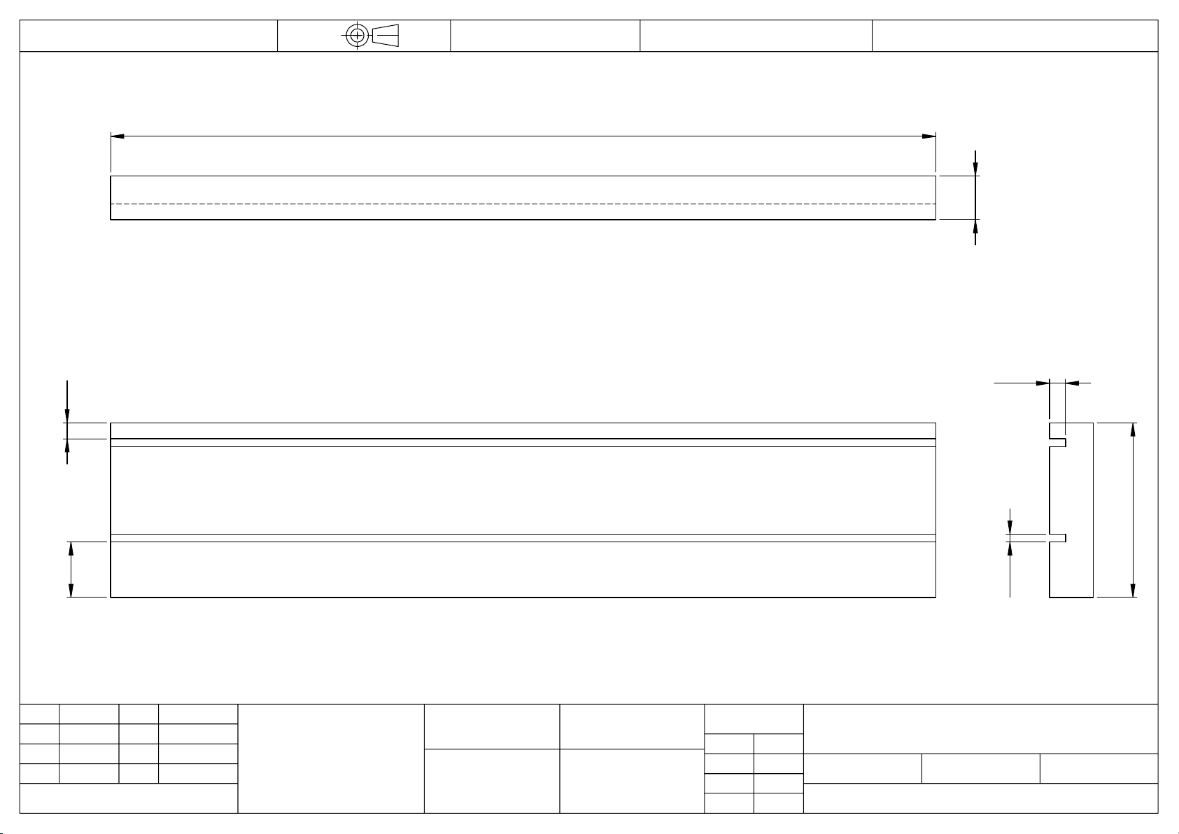
PC0001 –End Panel
Page 14
PC0002 –Side Panels
Page 15
PC0003 –Reduced End Panel
Page 16
ASSEMBLY DIAGRAMS
Page 17
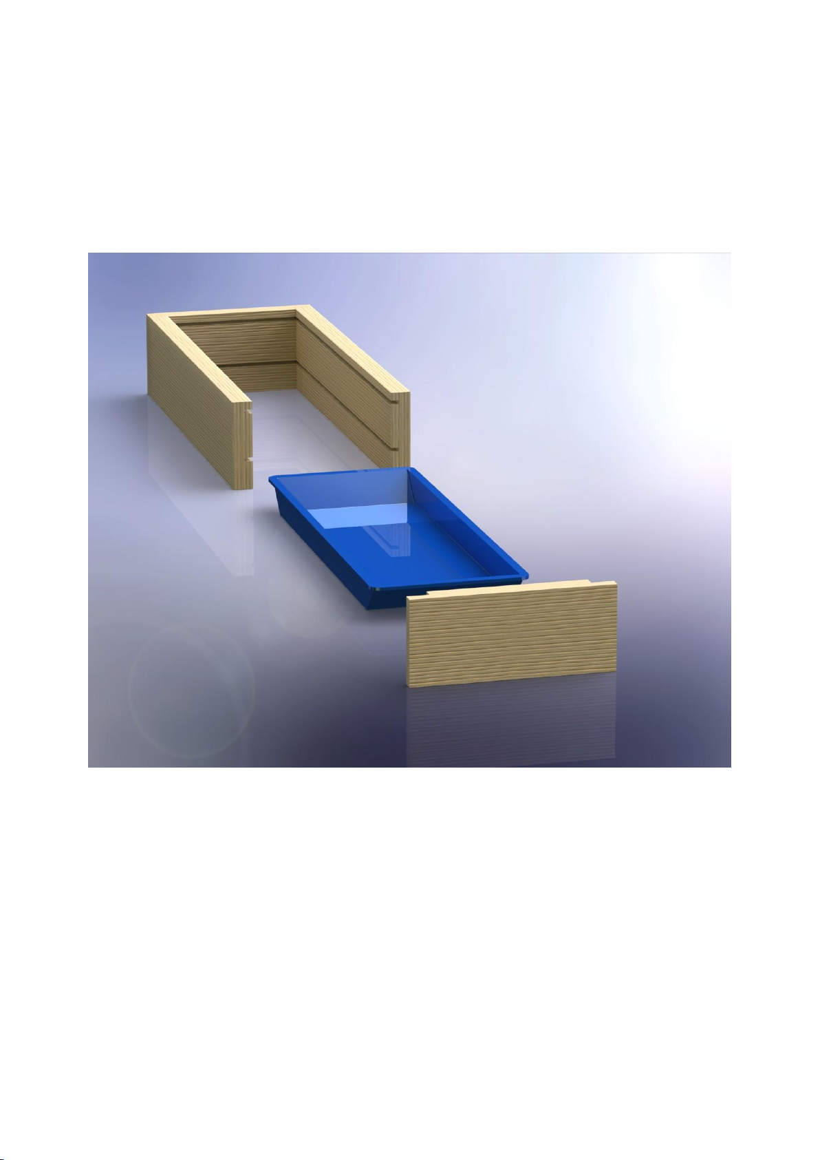
THE COMPLETED PENCIL CASE
Page 21

INTRODUCTION
THE GERBIL
The Gerbil is a unique machine that was originally designed as a safe and easy method of
trimming out vacuum formings. Over the years it has evolved and it is now a much more
versatile machine that can be used to perform a wide range of tasks. Resource Material G1
gives an overview of the different tasks that can be performed on the Gerbil.
OBJECTIVE:
The objective of the project is to build a pencil case. The case is made out of both plastic
and wooden materials.
TECHNIQUES:
The project will enable you to learn and practise the following techniques using the Gerbil:
1. Trimming out vacuum formings to give straight and flanged edges
2. Slotting and rebating wooden components
3. Polishing and finishing acrylic components
MATERIALS:
You will be provided with a set of materials. The pack should contain the following:
1. One vacuum forming, containing the shapes for the pencil case lid, base, and base
insert.
2. Two wooden side panels, measuring approx 207mm long x 11mm wide x 44mm
high.
3. Two wooden end panels, measuring approx. 91mm long x 11mm wide x 44mm high.
SAFETY:
Throughout the project, please observe the following safety instructions
1. Wear safety glasses at all times
2. Remove any loose jewellery
3. Tie back long hair
Page 1

INSTRUCTIONS
STAGE 1 –TRIMMING OUT THE VACUUM FORMINGS
1. In total there are 3 acrylic formings to be trimmed, all on one sheet. The lid is the
forming which has some writing embossed on it. The base insert has groves to hold
the pencils in place.
2. The base insert needs to have a straight edge. This requires using the Tungsten
Carbide Disc on the Gerbil o trim out the vacuum forming. For detailed instructions
refer to Resource Material G2
3. The lid and base need to have flanged edges, thereby enabling them to slide into the
wooden case. This requires using the flange cutter on the Gerbil to trim out the
vacuum forming. For detailed instructions refer to Resource Material G3
4. Once all three formings have been trimmed the edges may need to be finished
slightly to remove any rough edges. This requires using the mop on the Gerbil. For
detailed instructions refer to Resource Material G5. An alternative method would be
to use a metal file.
Page 2

INSTRUCTIONS - continued
STAGE 2 –SLOTTING THE PANELS
1. Cutting slots requires using the tungsten carbide disc, combined with the extraction
and guide fences. For detailed instructions refer to Resource Material G4
2. BOTH side panels need to have two slots along the length of the panels. Both slots
will remain as slots right through to the end. Please refer to schematic PC0002 on
page 14 for details.
3. ONE end panel –the “reduced end panel”–needs two slots along its length. One of
these slots will remain as a slot right through to the end. The other will set the line for
trimming this panel down to size later on. Please refer to schematic PC0003 on page
16 for details.
4. ONE end panel –the standard “end panel” – needs two slots along its length. Both
slots will remain as slots right through to the end. Please refer to schematic PC0001
on page 14 for details.
5. For the “bottom”slot, set the height of the disc so that the bottom of it is 14mm
above the table. To set the depth of the slot, position the extraction fence so that
between 4 and 5mm of the disc protrudes. This is the slot that will hold the base of
the case, and it applies to all four panels.
6. Position the panel so that a long edge rests on the table and set the guide fence
accordingly and cut the slot as detailed in Resource Material G4.
7. Repeat step 4 for the second side panel and for BOTH end panels
8. Check the size of the slots by sliding the trimmed base forming along it. If necessary,
raise the height of the disc by ~1mm, and repeat the cut along all of the slots in order
to make them wider.
9. The panels now require a “top”slot. This is the slot that will hold the lid of the case.
For the reduced end panel this is the slot that will set the line for trimming down later.
Note that both slots will be on the same face of the panels.
10.Set the height of the disc so that the bottom of it is 4mm from the table. The depth of
the slot is the same so there is no need to adjust the extraction fence position.
11.Rotate one of the side panels. The top slot needs to be on the same face of the
panel, and parallel to the bottom slot, but working from the other end.
Page 3

INSTRUCTIONS
STAGE 2 –continued
12.Set the guide-fence and cut the slot as detailed in Resource Material G4.
13.Repeat step 10 for the second side panel and for the standard end panel.
14.Check the size of the slots by sliding the trimmed lid forming along it. If necessary,
raise the height of the disc by ~1mm, and repeat the cut along all of the slots in order
to make them wider.
15.Clean off any dust along all of the slots. If necessary use a steel rule or sandpaper to
finish off any rough edges and clean inside the slot.
16.The side panels are now ready. Both end panels now require some rebating –move
on to STAGE 3
Page 4

INSTRUCTIONS
STAGE 3 –REBATING THE END PANELS
1. Cutting rebates requires using the tungsten carbide disc, combined with the
extraction and guide fences. It is carried out in two stages –first of all a slot is cut,
then the workpiece is turned by 90˚ and a second slot is cut to create the rebate. For
detailed instructions refer to Resource Material G4
2. Both end panels need to be rebated along both ends. Please refer to schematics
PC0001 and PC0003 on pages 14 and 16 for details. The rebates need to be on the
same side as the slots that have already been cut.
3. Set the height of the disc so that the BOTTOM of it is 10mm above the table. This
needs to match the thickness of the wood. Lay a piece of wood on the table next to
the disc, and make sure that the TOP of the disc is at the same height as the piece
of wood. To set the depth of the slot, position the extraction fence so that 5mm of the
disc protrudes.
4. Position the end panel so that a short edge rests on the table and the existing slots
from stage 2 face toward the disc. Set the guide fence and cut the slot as detailed in
Resource Material G4.
5. Rotate the panel and repeat step 4 along the other short edge. Repeat steps 4 and 5
for the reduced end panel.
6. Now the slots need to be turned into rebates. Re-set the height of the disc so that the
bottom of it is 6mm above the table. The depth of the slot also needs to be re-set by
re-positioning the extraction fence so that 11mm of the disc protrudes.
7. Position the end panel so that it lies flat on the outside face, so that the slot cut in
step 4 is parallel to the fence, and facing upwards. The slot you are about to cut
should be at right angles to this slot.
8. Set the guide fence and cut the slot, thereby removing a small strip of wood to create
the rebate. Care needs to be taken to hold the piece of wood steady as it passes
through the disc.
9. Repeat steps 9 and 10 for the other end of the end panel, and for both ends of the
reduced end panel. Clean off any dust along the rebates. Use sandpaper to finish
any rough edges.
10.The end panel is now ready for assembly however the reduced end panel needs one
more cut. Move on to stage 4
Page 5

INSTRUCTIONS
STAGE 4 –TRIMMING THE REDUCED END PANEL DOWN TO SIZE
1. The reduced end panel needs to be slightly shorter so that the lid of the pencil case
can be slid in and out.
2. Use the slotted reduced end panel as a guide to set the height of the disc. The disc
should be at the height of the existing “top” slot. This is the slot that is 4mm from a
long edge of the panel. Set the disc so that 7mm of it protrudes.
3. Position the panel so that the existing slots face AWAY from the disc, with the “top”
slot along the bottom. This new cut should line up with the “top” slot, meeting it in
the middle and thereby removing a strip of wood to make this panel shorter
4. Set the guide fence accordingly and cut the slot as detailed in Resource Material
G4.
5. Clean off any dust along the rebates. If necessary use sandpaper to finish any
rough edges.
STAGE 5 –ASSEMBLY
1. First of all look at the diagram on page 21 to see what the end result should look like.
The panels need to be glued together and ideally tacked as well for extra stability.
2. Line up the two side panels against the standard end panel rebates so that the slots
are in line along the inside of the case. Refer to the diagram on page 18 for details.
3. Apply some wood glue to the rebated edges on the standard end panel. Slide the
base forming in along the bottom slots. Hammer in 4 tacks, one in each corner, as
shown in the diagram on page 18.
4. Position the reduced end panel so that it is ready to be glued on to the rest of the
case, and apply some glue to the rebated edges. Glue together and hammer in 4
tacks, one in each corner as in step 3. If you are not using tacks, it is necessary to
use some tape to hold the case together while the glue dries.
5. Insert the base insert into the case, and slide the lid forming along the top slots.
Refer to the diagrams on pages 19 and 20 for details.
6. The pencil case is now complete and just needs to be left until the glue is
thoroughly dry. Once the glue is dry, smooth of any edges using the Antelope
Bandfacer.
Page 6

RESOURCE MATERIALS
Page 7

1. The Gerbil
The Gerbil is a versatile work table, for use by students in the classroom, into which can be mounted
a variety of tools for working on plastic, wood and metal. There are three models, the basic 2010,
fitted with a trimming disc, the 2020, which has extra features such as a tilting table, extraction and a
range of tools, and the 2030, which features a 2020 model with a purpose-built trolley.
2. Trimming out Vacuum Formings
A common application is for trimming out shapes formed by a vacuum from a
sheet of plastic. The advantage of the Gerbil over other techniques, such as
using a band saw or Stanley knife, is that the process is accurate, controllable,
and above all safe.
The formings can be cut out using either a trimming disc or a flange cutter. The
disc works from inside the forming and produces a straight edge. The flange
cutter works from outside the forming and leaves a flanged edge. The flange
may be appropriate, for example, if two pieces are to be joined together.
Instructions for disc and flange trimming. See Resource Materials G2 and G3.
3. Sanding and Finishing
A drum sander or flap wheel can be fitted in place of a trimming tool. This can
be used for finishing any rough edges left by the trimmer, for shaping profiles in
the forming, or for working on the mould itself. When used with the adjustable
tilting table, for example, you can produce a slanted or chamfered edge on the
mould (often known as the “Draft Angle”) which makes it easier to withdraw the
mould from the forming. See Resource Material G4.
Similarly, a mini mop can be fitted for the polishing or finishing of pieces of
acrylic. This is particularly useful for the finishing of small components, as this
can be hazardous on a full size polisher.
4. Cutting Slots and Rebates
With the addition of the guide fences, the Gerbil’s disc can be used to make
slots and rebates in soft wood. This is ideal, for example, for making a lid for a
box, or slots to divide a box into compartments. See Resource Material G5.
2010
2020
2030
Page 8
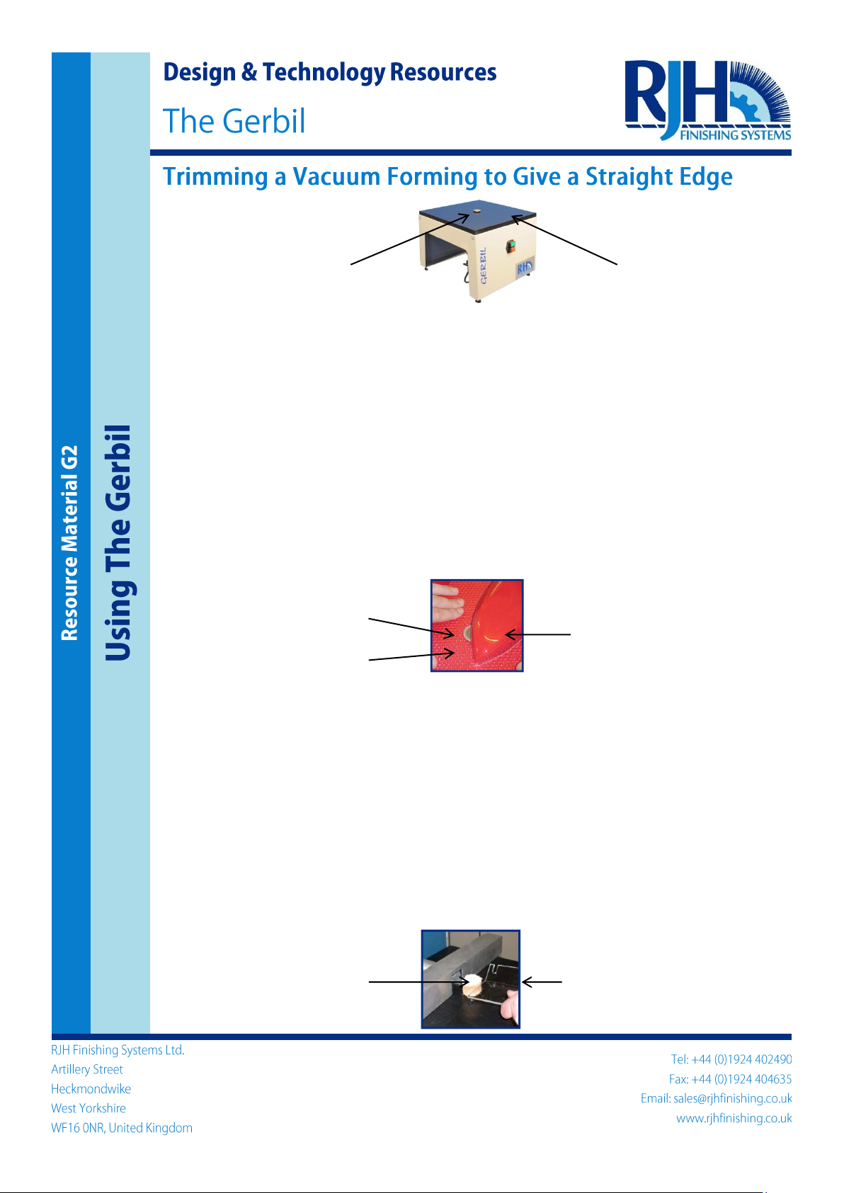
Both the 2010 and 2020 Gerbils can be used with the tungsten carbide abrasive disc to trim out
vacuum formings leaving a straight edge.
1. The following safety instructions must be observed at all times: wear safety goggles, tie back
long hair and remove any loose jewellery.
2. Fit the abrasive disc as described in the instruction manual. Set the cutting height as required.
3. Place the vacuum forming over the top of the disc and make sure that it is seated flat on the
table. You should not be able to see the disc as it will be hidden beneath the vacuum forming.
4. You can hold the vacuum forming in place however best suits you, but be careful not to apply
too much pressure or the forming may distort. It is best to apply pressure to the waste plastic
around the edge, and, if you need to, simply rest a hand on the forming to guide it as you trim.
5. Switch on the machine. Holding the vacuum forming as instructed in (4) push the vacuum
forming against the rotating disc so that it trims through the wall of the forming (see figure
below); about half of the disc will now be visible. If you have the 2020, you can use the table
top cross hairs to give an estimated position of the disc.
6. Gradually move the abrasive around the vacuum forming, clockwise or anticlockwise, at a slow,
steady rate. If you rush or push too quickly you will leave a rough finish which will need more
sanding later. When the disc is within 20mm of the starting point, reduce the rate at which you
are moving the forming and gradually complete the operation.
7. Switch off the Gerbil, remove the vacuum forming and clear the waste plastic from the table.
8. Allow the forming to cool.
9. The base of the vacuum forming may now need a small amount of finishing work. This should
be done in two stages:
a) Break off any large pieces of plastic swarf with your fingers.
b) Use the mini mop to finish any rough edges (see Resource Material G5). If you do not have
this tool you can use the edge of a steel rule, or a piece of abrasive paper. Be careful when
sanding not to dwell too long on one spot, for fear of rubbing away too much material.
10. You should now ask your teacher if any more finishing is needed.
Table Top
Trimming Disc
Trimming Disc
Waste Plastic
Plastic Forming
Polishing Mop
Trimmed Forming
Page 9
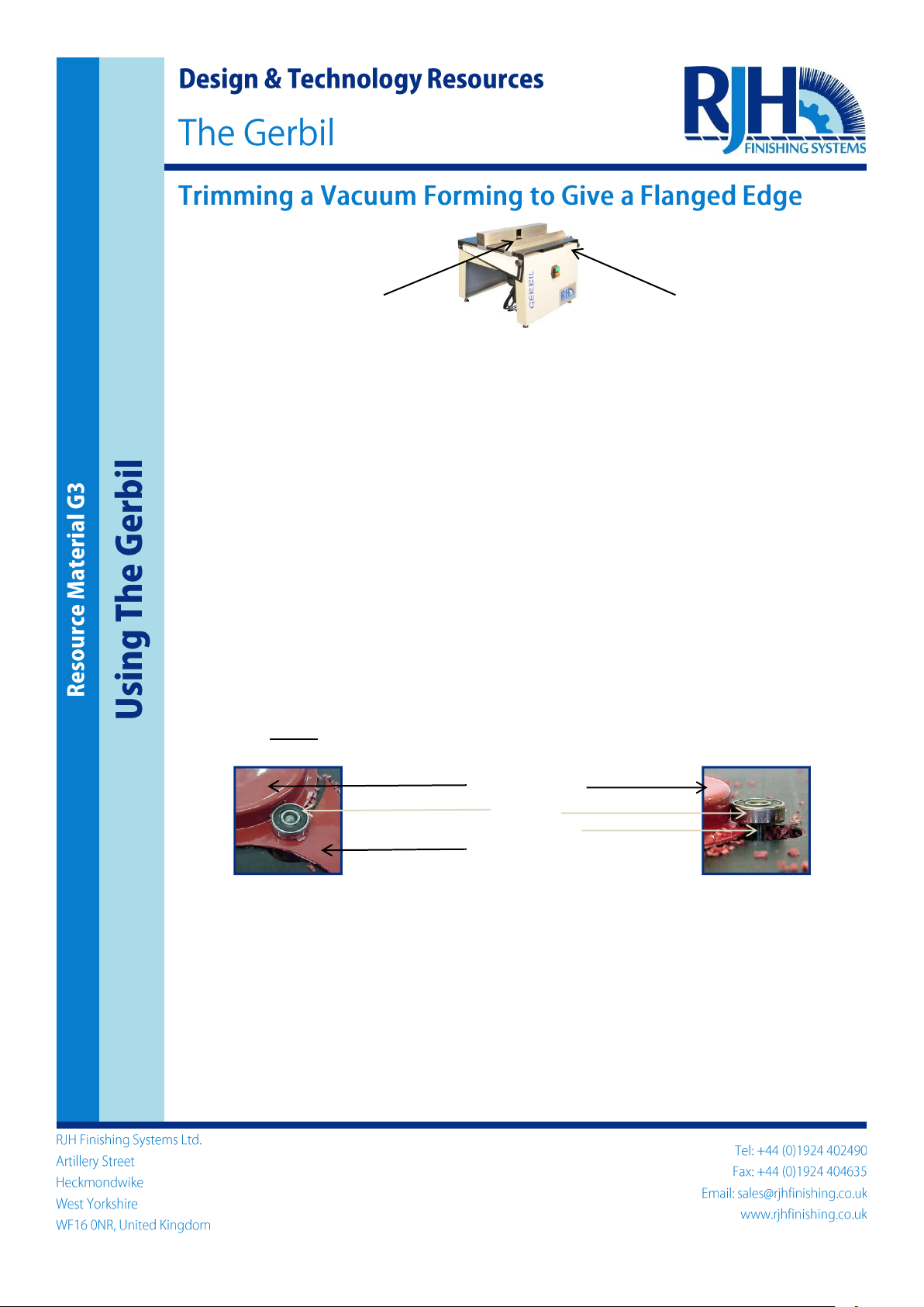
The 2020 Gerbil is supplied with a flange cutter to cut out vacuum formings so as to leave a flanged
base. A flange may be necessary, for example, to provide a surface for sticking two formings
together. The cutter can also be supplied separately and fitted to the 2010 model.
The flange tool consists of a cutter shielded by bearings above and below the table. The bearings
serve both to hide the blade for safety and to act as a spacer controlling the width of the flange.
1. The following safety instructions must be observed at all times: wear safety goggles, tie back
long hair and remove any loose jewellery.
2. Fit the flange cutter as described in the instruction manual.
3. Place the vacuum forming to be trimmed alongside the cutter and make sure that it is seated
flat on the table top of the Gerbil.
4. You can hold the vacuum forming in place however best suits you, but note that you do not
need to apply as much pressure with the flange cutter as you do with the cutting disc; simply
guide the forming in the right direction.
5. Switch on the machine. Holding the vacuum forming as instructed in (4) guide the forming
towards the cutter, allowing the tool to cut a path through the waste plastic to the edge of the
vacuum forming. The bearing should be visible all of the time, moving over the top of the
plastic.
6. When the cutter reaches the forming, so that the bearing is resting against it, you can start
cutting around the forming. Do this by keeping the cutter moving at a steady rate clockwise
around the forming (see pictures below).
Plastic Forming
Bearing
Flange Cutter
Waste Plastic
7. Make sure that the bearing maintains contact with the side of the vacuum forming so that the
flange width is constant.
8. When the cutter is within 20mm of the starting position, slow down and very carefully complete
the cut.
9. Switch off the Gerbil, remove the vacuum forming and clear the waste plastic from the table.
10. Note that you can use the flange cutter to work in more than one plane of the forming. For
example, if cutting out a vacuum formed car, you can use the tool to form the wheel arches,
after you have cut out the car body from the plastic sheet.
11. Allow the forming to cool.
12. The base of the vacuum forming may now need a small amount of finishing. Please refer to
step 9 of Resource Material G2.
Table Top
Flange Cutter
Page 10

Design&TechnologyResources
TheGerbil
UsingtheGerbiltoCutSlotsandRebates
ResourceMaterialG4
UsingTheGerbil
By using the tungsten carbide abrasive disc and the guide and extraction fences on the Gerbil 2020,
it is possible to cut slots and rebates in softwood. This is very useful for making wooden boxes or
enclosures.
1. The following safety instructions must be observed at all times: wear safety goggles, tie back
long hair and remove any loose jewellery.
2. Fit the abrasive disc as described in the instruction manual and adjust the height of the disc to
set the position of the slot above the base of the wooden item.
3. Install the guide fence and dust extraction fence as outlined in the manual. The distance
between the front of the dust extraction fence and the front edge of the tungsten carbide disc
sets the depth of the slot.
Dus ce
Tungsten Carbide Disc
12. tion fence further back and repeat the cut. t.
RJHFinishingSystemsLt
ArtilleryStreet
dKingdom
4402490
Email:
t Extraction Fen
Guide Fence
4. Place the wooden workpiece against the dust extraction fence. Then push the guide fence
against the workpiece. Secure by tightening the Kip lock. Make sure that the workpiece is free
to travel all the way along the fences without becoming stuck.
5. Attach the vacuum cleaner hose to the extraction fence dust outlet.
6. Switch on the Gerbil and turn on the vacuum cleaner.
7. Push the workpiece towards the disc at a slow, steady rate, as shown in the picture below.
Work from right to left, so that the wood is pushing against the rotation of the disc.
8. Use another piece of wood to push the workpiece along - do not use your fingers to push.
However you may need to use your left hand to hold the top of the workpiece steady as it
moves along.
9. Switch off the Gerbil.
10. Clean off the dust. You can use a steel rule to clean inside the slot. Your slot is now finished.
11. To make a rebate, you can make it by turning the workpiece by 90° and repeating steps (4) to
(9). Your rebate is now finished.
To deepen the slot, move the dust extrac
13. Similarly, you can widen the slot by raising the height of the tool and repeating the cu
d. Tel:+44(0)192
Heckmondwike
WestYorkshire
WF160NR,Unite
Fax:+44(0)1924404635
sales@rjhfinishing.co.uk
www.rjhfinishing.co.uk
Tungsten Carbide Disc
Dust Extraction Fence Guide Fence
Page 11

Gerbil 2020
By using the mini mops and compound bars on the Gerbil 2020 it is possible to finish the edges of
plastic components. This is particularly useful for the finishing of small pieces, as this can be
hazardous on a full size polisher. The mops and compound bars can also be supplied separately
and fitted to the 2010 model.
1. The following safety instructions must be observed at all times: wear safety goggles, tie back
long hair and remove any loose jewellery.
2. Select your preferred mop and compound bar –there are two to choose from; the polishing mop
and bar and the finishing mop and bar.
3. Fit the mop as described in the instruction manual.
4. Switch on the Gerbil, and apply compound by gently holding it against the rotating mop. See
image below.
5. To finish the plastic edge, gently press the workpiece against the mop. Steadily move the
component up and down and at different angles so as to finish the entire edge.
6. Be sure to hold onto the component firmly so that it is not pulled away by the moving mop.
Please note however that the slow running speed of the mop means that even if this were to
happen there would be no danger to the operator, it would simply disrupt the finishing process.
7. Periodically lift the component away from the mop and feel the edge to check the finish. If
necessary apply more compound.
8. When you are happy that the edge is smooth enough then switch of the Gerbil.
Extraction Fence
Mini Mop
Compound Bar
Piece of Acrylic
Page 12

SCHEMATICS
Page 13
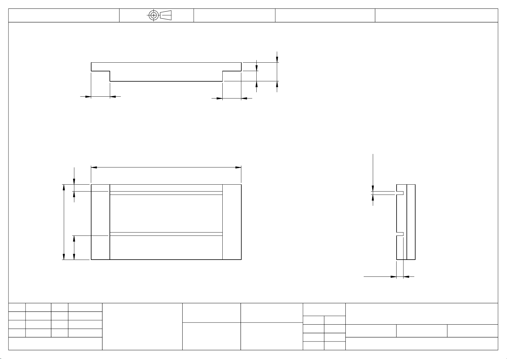
89.00
88.00
44
14
4
5.00
4.00
3.00
2.00
11
6
11
11
DATE
This drawing remains the
property of
RJH Finishing Systems Ltd.
and must not be loaned or
copied without written
permission from the company.
Copyright Reserved ©
ALT. DIM POS
MS
19.09.12
MODIFICATIONS
PC0001
DWG NO.
IF IN DOUBT ASK
PROJECTION:
softwood
SHEET:
SCALE:
A
NOTE N
O
INITIALS
DATE
ISSUE
28.08.12
UNLESS OTHERWISE SPECIFIED:
DIMENSIONS ARE IN MILLIMETERS (mm)
GENERAL SURFACE FINISH: 1.6RA
TOLERANCES: LINEAR: ±0.5
ANGULAR: WHOLE DEGREES ±0.5°,
CONCENTRICITY: WITHIN 0.05
1 OFF
QTY:
DWG NO.
CHK'D
DATE
DRAWN
MS
DO NOT SCALE DRAWING
A4
FINISH:
1:1
1 OF 1
natural
PC0001
End Panel
DEBUR AND BREAK SHARP EDGES
SHEET:
TITLE:
MATERIAL:
RJH Finishing Systems Ltd.
Artillery Street,
Heckmondwike,
West Yorkshire,
WF16 0NR.
Tel: (01924) 402490
Fax: (01924) 404635
B
ALT. DIM POS
MS
10.10.12
16.10.12
ALT. DIM POS
MS
C
Page 14
14
4
210.00
208.00
11
5.00
4.00
44
3.00
2.00
DATE
This drawing remains the
property of
RJH Finishing Systems Ltd.
and must not be loaned or
copied without written
permission from the company.
Copyright Reserved ©
ALT. DIM POS
MS
19.09.12
MODIFICATIONS
PC0002
DWG NO.
IF IN DOUBT ASK
PROJECTION:
softwood
SHEET:
SCALE:
A
NOTE N
O
INITIALS
DATE
ISSUE
29.08.12
UNLESS OTHERWISE SPECIFIED:
DIMENSIONS ARE IN MILLIMETERS (mm)
GENERAL SURFACE FINISH: 1.6RA
TOLERANCES: LINEAR: ±0.5
ANGULAR: WHOLE DEGREES ±0.5°,
CONCENTRICITY: WITHIN 0.05
2 OFF
QTY:
DWG NO.
CHK'D
DATE
DRAWN
MS
DO NOT SCALE DRAWING
A4
FINISH:
1:1
1 OF 1
natural
PC0002
SIDE PANEL
DEBUR AND BREAK SHARP EDGES
SHEET:
TITLE:
MATERIAL:
RJH Finishing Systems Ltd.
Artillery Street,
Heckmondwike,
West Yorkshire,
WF16 0NR.
Tel: (01924) 402490
Fax: (01924) 404635
B
ALT. DIM POS
MS
10.10.12
C
ALT. DIM POS
MS
16.10.12
Page 15

89.00
88.00
14
38
6
11
11 11
5.00
4.00
3.00
2.00
DATE
This drawing remains the
property of
RJH Finishing Systems Ltd.
and must not be loaned or
copied without written
permission from the company.
Copyright Reserved ©
ALT. DIM
MS
10.10.12
MODIFICATIONS
PC0003
DWG NO.
IF IN DOUBT ASK
PROJECTION:
softwood
SHEET:
SCALE:
A
NOTE N
O
INITIALS
DATE
ISSUE
29.08.12
UNLESS OTHERWISE SPECIFIED:
DIMENSIONS ARE IN MILLIMETERS (mm)
GENERAL SURFACE FINISH: 1.6RA
TOLERANCES: LINEAR: ±0.5
ANGULAR: WHOLE DEGREES ±0.5°,
CONCENTRICITY: WITHIN 0.05
1 OFF
QTY:
DWG NO.
CHK'D
DATE
DRAWN
MS
DO NOT SCALE DRAWING
A4
FINISH:
1:1
1 OF 1
natural
PC0003
Reduced End Panel
DEBUR AND BREAK SHARP EDGES
SHEET:
TITLE:
MATERIAL:
RJH Finishing Systems Ltd.
Artillery Street,
Heckmondwike,
West Yorkshire,
WF16 0NR.
Tel: (01924) 402490
Fax: (01924) 404635
B
ALT. DIM
MS
16.10.12
Page 16

ASSEMBLY DIAGRAMS
Page 17
ASSEMBLY STEP 1
Page 18
This manual suits for next models
2
Table of contents
Popular Industrial Equipment manuals by other brands


woodmizer
woodmizer LT40AC Remote - ST Operator's manual

Premier Manufacturing Co.
Premier Manufacturing Co. 235SM Installation, Inspection, Operation & Maintenance Guide

woodmizer
woodmizer LubeMizer manual

woodmizer
woodmizer LASTEC 621ER Product information bulletin

Alfalaval
Alfalaval AC instruction manual

YILMAZ
YILMAZ PCC 6505 manual


