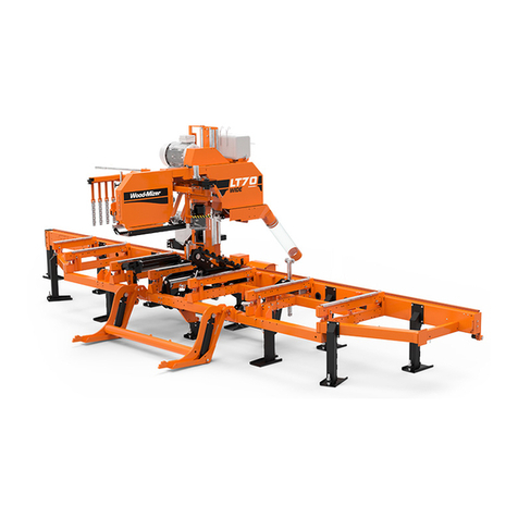
Table of Contents Section-Page
2 ROdoc101921 Table of Contents
SECTION 1 REMOTE OPERATION 1-1
1.1 Preparing for Remote Operation ............................................................................... 1-2
1.2 Remote Sawmill Operation ....................................................................................... 1-4
1.3 Preparing The Remote Option For Towing............................................................... 1-5
1.4 Cold Weather Operation............................................................................................ 1-6
1.5 Hydraulic Control Operation..................................................................................... 1-7
1.6 Loading, Turning, And Clamping Logs .................................................................... 1-9
SECTION 2 MAINTENANCE & TROUBLESHOOTING 2-1
2.1 Clean The Cable Chain & Support Tray ................................................................... 2-1
2.2 Cable Chain Repair.................................................................................................... 2-2
2.3 Cable Chain And Support Tray Alignment............................................................... 2-3
2.4 Board Removal Bumper Adjustment ........................................................................ 2-5
SECTION 3 REPLACEMENT PARTS 3-1
3.1 How To Use The Parts List ....................................................................................... 3-2
3.2 Sample Assembly ...................................................................................................... 3-2
Protective Conduits, LT70L Super Hydraulic Hoses
3.3 Remote Control Box ................................................................................................ 3-4
3.4 Remote Control Box M-Super frame ................................................................... 3-6
3.5 Electric Box Base ................................................................................................. 3-8
3.6 Adaptation Kit, Board Removal Bumper .............................................................. 3-9
3.7 Board Removal Bumper ...................................................................................... 3-10
3.8 Board Removal Bumper Assembly ...................................................................... 3-12
3.9 Board Removal Bumper ...................................................................................... 3-13
3.10 Remote Equipment for Installation on a Wall (Cutting Length of 6.5 m) ............ 3-15
3.11 Remote Equipment for Installation on a Wall (Cutting Length of 6.5-10 m ) ...... 3-16
3.12 Guide Rail Support Post ........................................................................................ 3-17
3.13 Guide Rail Support Post ..................................................................................... 3-19
3.14 4-Post Remote Set ................................................................................................. 3-21
3.15 5-Post Remote Set ................................................................................................. 3-22
3.16 Support Assembly, Hoses & Cables ..................................................................... 3-23
3.17 Support Assembly, Hoses & Cables ..................................................................... 3-24
3.18 Support Assembly, Hoses & Cables ..................................................................... 3-25
3.19 Support Assembly, Hoses & Cables ..................................................................... 3-26
3.20 Board Return Assembly ...................................................................................... 3-27
3.21 Board Return Guide .............................................................................................. 3-28
3.22 Board Return Arm ............................................................................................... 3-30
3.23 Electric Box, ST 4 kW (557006) .......................................................................... 3-32
3.24 Electric Box, ST 4 kW (557003) ......................................................................... 3-33
3.25 Roller with Rubber Bushing ................................................................................. 3-34
SECTION 4 ELECTRICAL WIRING DIAGRAMS, LT40ME20SRAH4-ST 4-1
