System air SAVE VTR 250/B User manual

Document translated from English | 213005 · v01_1.8.0
SAVE VTR 250/B
GB User Manual................................................2
SV Användarhandbok .....................................18
DE Bedienungsanleitung .................................34
FI Käyttöohje................................................50

213005 | v01_1.8.0
Contents
1 Overview ......................................................5
1.1 General Description ................................5
1.2 Warranty..............................................5
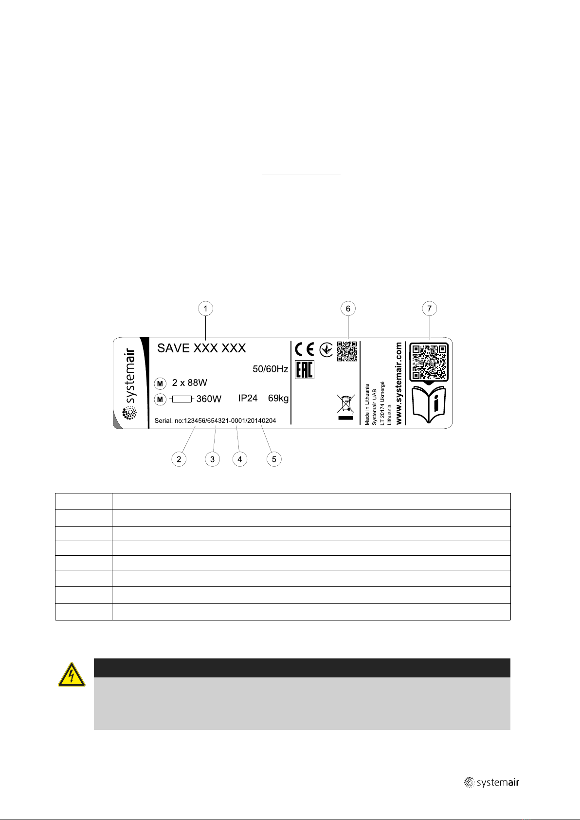
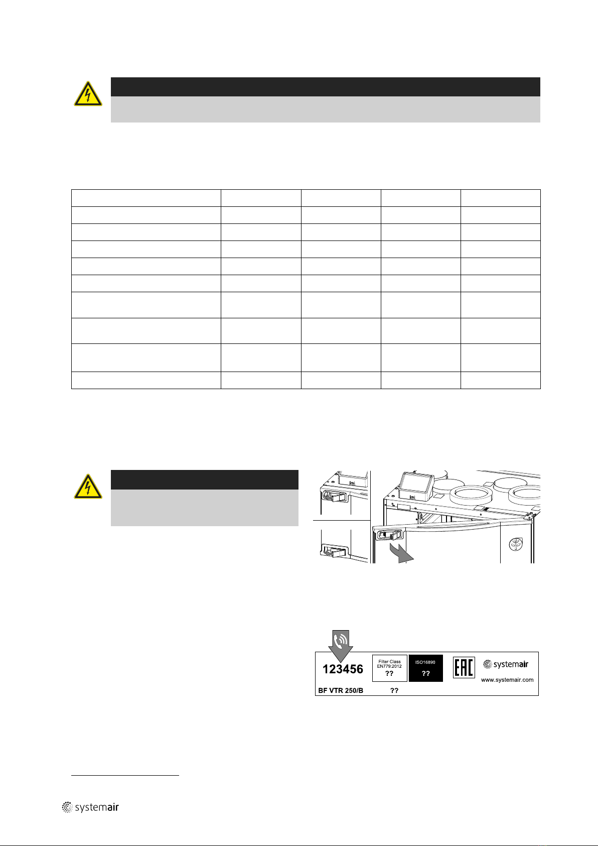
1.3 Type label.............................................5
2 Warnings.......................................................5
3 Control Panel..................................................6
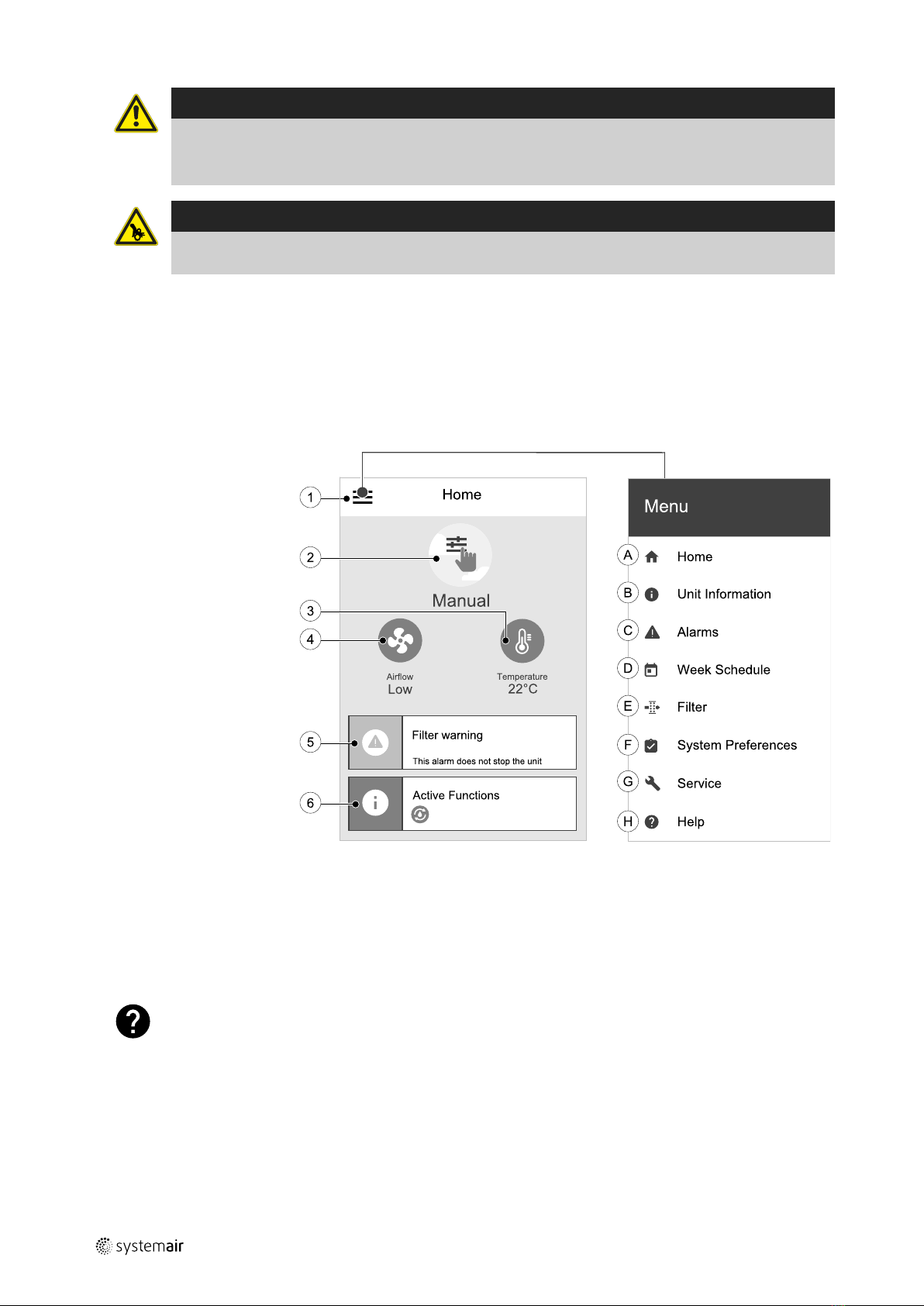
3.1 Home Screen And Menu ..........................6
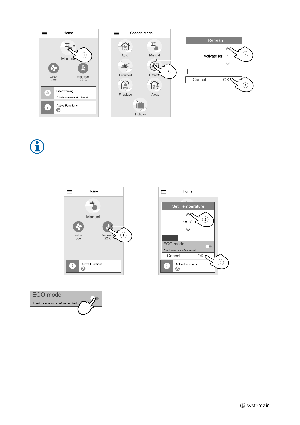
3.2 How to Select User Mode.........................6
3.3 How to Change Temperature ....................7
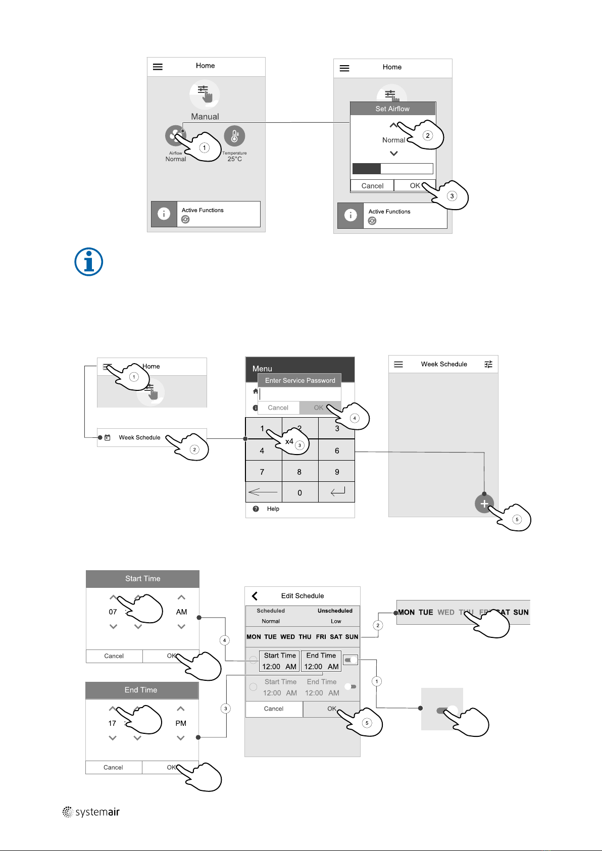
3.4 How to Change Airflow............................7
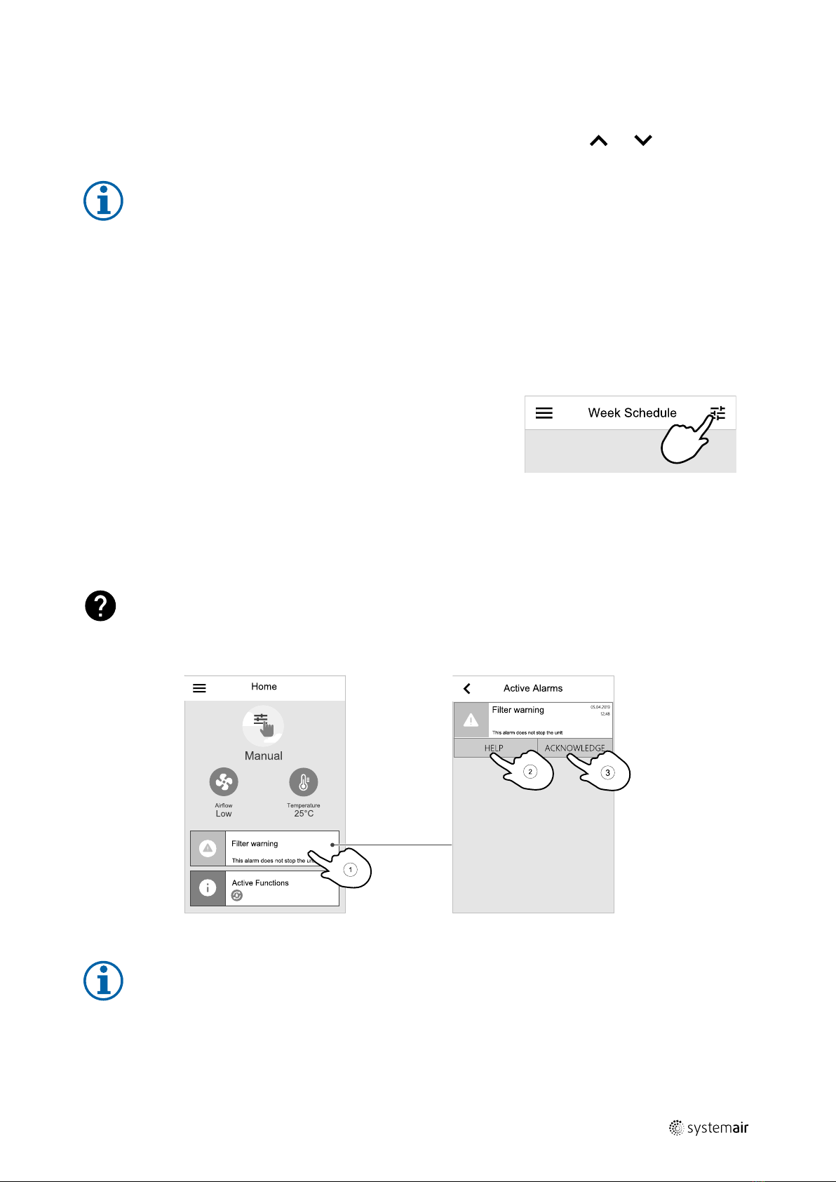
3.5 How to Set Week Schedule.......................8
3.5.1 Schedule airflow settings .............9
3.6 Status Line and Alarms ............................9
4 Maintenance................................................ 10
4.1 Maintenance Schedule .......................... 10
4.2 Open the front hatch............................. 10
4.3 Changing filters.................................... 10
4.3.1 Resetting the Filter Change
Time...................................... 11
4.4 Check and Clean a Heat
Exchanger .......................................... 12
4.5 Check and Clean Fans............................ 12
4.6 Replacing rotor drive belt ....................... 13
4.6.1 Temporary belt repair
solution.................................. 13
4.7 Duct System Maintenance...................... 14
4.7.1 Cleaning extract louvres and
supply air diffusers ................... 14
4.7.2 Checking the outdoor air
intake .................................... 14
4.7.3 Checking the roof cowl (if
fitted).................................... 14
4.7.4 Checking and cleaning the
duct system ............................ 14
5 Troubleshooting............................................ 14
6 Electrical data............................................... 15
7 Disposal and recycling .................................... 16


GB Overview |5
1 Overview
1.1 General Description
This manual describes basic information how to operate and perform maintenance on the unit and the system it is con-
nected to.
Read the instructions carefully and in its entirety.
For description of advanced settings and installation of accessories see Service and Accessories Installation manual.
All documents can be found in our online catalogue at www.systemair.com.
1.2 Warranty
For the assertion of warranty claims, the products must be correctly connected and operated, and used in accordance
with the data sheets. Further prerequisites are a completed maintenance plan with no gaps and a commissioning re-
port. Systemair will require these in the case of a warranty claim.
1.3 Type label
Before calling your service representative, make a note of the specification and production number from the type label,
which can be found next to the external connections and inside of the unit.
Fig. 1 Type label
Position Description
1Product code (product specification)
2Product item number
3Production order number
4Serial number
5Production date (YY.MM.DD)
6QR code for manufacturing order (MO) number and software version
7QR code for the spare parts list and documentation
2 Warnings
Danger
• Make sure that the mains supply to the unit is disconnected before performing any maintenance or
electrical work!
• All electrical connections and maintenance work must be carried out by an authorized installer and in
accordance with local rules and regulations.
213005 | v01_1.8.0

6| Control Panel GB
Warning
• This product must only be operated by a person who has suitable knowledge or training within this field
or carried out with the supervision of a suitably qualified person.
• Beware of sharp edges during mounting and maintenance. Use protective gloves.
Warning
• All though the mains supply to the unit has been disconnected there is still risk for injury due to rotating
parts that have not come to a complete standstill.
3 Control Panel
SAVE Touch is a new generation control panel with a touch screen.
Settings are done by touching the icons or options. The touch screen is sensitive and it is not necessary to press too
hard.
3.1 Home Screen And Menu
1. Menu
2. Active user mode
3. Airflow settings
4. Temperature settings
5. Alarms and warnings
6. Status line
A.Return to home screen
B. Basic read-only information about the unit
C. Currently active alarms and alarm history
D. Configure and check week schedule
E. Check and change remaining time till filter change
F. General system preferences
G.Configuration of all system parameters
H.Help and troubleshooting menu
3.2 How to Select User Mode
For more information about user modes and functions, please check Help menu.
The top circle on the home screen indicates a currently active user mode. Touch the symbol to change the mode.
213005 | v01_1.8.0

GB Control Panel | 7
Duration have to be set for temporary user modes. SAVE VTR 250/B will return to its previous working mode after the
set time expires.
Note:
AUTO mode is available for selection only if the optional Demand Control,Week Schedule and/or
external fan control functions are activated.
3.3 How to Change Temperature
Touch the thermometer symbol on the home screen to open the temperature settings window.
Use up and down arrows to increase or decrease a value. The default setting is 18 °C.
ECO mode is a power saving function which partially limits heater operation and
can only be activated if a heater is installed.
3.4 How to Change Airflow
Touch the fan symbol on the home screen. In the open window use up or down arrows to increase or decrease the
speed of fans.
213005 | v01_1.8.0

8| Control Panel GB
Note:
Airflow regulation is available only in Manual mode.
3.5 How to Set Week Schedule
While in home screen, touch menu icon and select Week Schedule.
The menu is locked by default. Enter a password (default password is 1111).
Touch icon at the bottom left corner of the screen to add a new schedule or press EDIT button to modify already added
schedule.
213005 | v01_1.8.0

GB Control Panel | 9
Week Schedule is active only during AUTO mode.
Touch the slider to the right to activate scheduled period.
Set the time. Touch the START TIME or END TIME values to change time. Use arrow buttons and to increase or
decrease value. Confirm with OK button.
Note:
Scheduled time can start but never end at midnight (00:00). The latest END TIME period is 23:59. Scheduled
time cannot go to the next day.
12 or 24 hour time format can be changed in System Preferences menu.
If necessary, activate second scheduled period and set up time.
Once time is set, click on the day(s) when schedule should be active. It is possible to set a separate schedule for each
day. Already scheduled days are not available for selection for new schedules.
Confirm schedule with OK button.
3.5.1 Schedule airflow settings
Touch settings icon to go to SCHEDULE AIRFLOW SETTINGS menu. In this
menu set airflow level for scheduled and unscheduled periods. Available lev-
els: Off,Low,Normal,High or Demand.
Set temperature setpoint offset for both periods (-10°C – 0°C).
Demand level is available only if Demand Control or External fan function is active.
3.6 Status Line and Alarms
Status line indicates all currently active functions. Touch the status line to see descriptions of active functions in more
detail.
For more information about user modes and functions, please check Help menu.
Alarms
Touch the alarm indicator on the home screen to see all active alarms.
Touch HELP button to know more about the alarm. To clear the alarm, touch ACKNOWLEDGE button.
Note:
The underlying cause of the alarm must be resolved first otherwise the alarm will appear again.
213005 | v01_1.8.0

10 |Maintenance GB
4 Maintenance
Danger
• Make sure that the mains supply to the unit is disconnected before performing any maintenance or
electrical work!
Warranty claims can only be made if maintenance work is carried out correctly and written evidence thereof is
provided.
4.1 Maintenance Schedule
Task 6 months 1 year 3 years When necessary
General inspection X
Filter change X X
Fan cleaning X
Heat exchanger cleaning X X
Belt replacement X
Checking and cleaning louvres/
diffusers
X
Checking and cleaning outdoor air
intake
X
Checking and cleaning roof cowl (if
fitted)
X
Cleaning of duct system X1
1. It is recommended to do this every 5 years and is normally carried out by authorized companies specialized in this area.
• Use original spare parts from Systemair only.
• Scan QR code on the type label to find a spare part list.
4.2 Open the front hatch
Danger
• Make sure that the mains supply to the unit
is disconnected before performing any
maintenance or electrical work!
Open the hatch with the two latches and swing the hatch
open.
4.3 Changing filters
The filters cannot be cleaned and must be changed as necessary. This is normally done 1–2 times per year depending
on the air pollution at the installation site.
It is very important to change filters regularly for perform-
ance and energy efficiency of the unit.
Each filter has a label with an part number for identifica-
tion. Provide this number when ordering new filters.
When it’s time to change the filters an alarm is shown on the control panel display. When this occurs do the following:
213005 | v01_1.8.0
1

GB Maintenance |11
1 Stop the unit by disconnecting the mains.
2 Open the front hatch. See chapter 4.2.
3 To remove the supply air filter loosen the knobs to remove the filter lock
(image shows when filter is hidden). Only one of the filter locks needs to
be removed.
4 Wiggle the filter and pull it out.
5 Insert the new filters. Make sure that the correct filter types are inserted.
6 Close and lock the front hatch and connect the unit to mains.
7 Reset the filter time. See chapter 4.3.1.
4.3.1 Resetting the Filter Change Time
Once filter is changed, it is necessary to reset filter time. Go to Filter menu
(see 3.1 Home Screen And Menu, page 6, pos. E) or if filter alarm is present,
click on alarm status line (see 3.1 Home Screen And Menu, page 6, pos. 5)
and select filter alarm. Select CHANGE FILTER, in the pop up menu define a
new filter period and press OK to confirm selection.
Note:
The menu is locked by default. Enter a password (default
password is 1111).
213005 | v01_1.8.0

12 |Maintenance GB
4.4 Check and Clean a Heat Exchanger
Warning
• Beware of sharp edges during mounting and maintenance. Use protective gloves.
Even if the required maintenance is carried out, dust will build up in the ex-
changer block. It is therefore of vital importance for the upkeep of a high effi-
ciency that the exchanger block is removed from the unit and cleaned
periodically as described below. Clean the heat exchanger at least every 3
years or when required.
1. Stop the unit by disconnecting the mains.
2. Open the front hatch. See chapter 4.2.
3. Disconnect the rotor power supply and the rotor sensor. The cables are
found beside the rotor at the back.
4. Pull out the rotor towards you. Some force may be needed.
5. Gently vacuum the heat exchanger.
Warning
Ensure the rotor motor is not exposed to moisture
6. Remount the rotor. Don’t forget to reconnect the rotor power and sensor
cables.
7. Close and lock the front hatch and connect the unit to mains.
4.5 Check and Clean Fans
Danger
• Make sure that the mains supply to the unit is disconnected before performing any maintenance or
electrical work!
Warning
• Risk of injury due to rotating parts that have not come to a complete standstill after mains supply to the
unit have been disconnected.
Warning
• Beware of sharp edges during mounting and maintenance. Use protective gloves.
Fig. 1 Extract and supply air fans
The motor bearings are life time lubricated and maintenance free.
Even if the required maintenance, such as changing of filters is carried out,
dust and grease may slowly build up inside the fans. This will reduce the
efficiency.
The fans may be cleaned as illustrated in below procedure.
1. Disconnect the fan power cables. The cables are found beside the fans.
2. Remove knobs that hold fans in place.
3. Pull out the fans towards you. Some force may be needed.
4. Clean the fans with a cloth or a soft brush. Do not use water. White spirit
can be used to remove obstinate deposits.
Allow the fans to dry properly before remounting.
5. Remount the fans. Don’t forget to reconnect the fan power cables.
213005 | v01_1.8.0

GB Maintenance |13
4.6 Replacing rotor drive belt
Fig. 2 Rotor drive belt
Danger
• Make sure that the mains supply to the unit is disconnected
before performing any maintenance or electrical work!
Warning
• Risk of personal injury! The heat exchanger weighs about 14
kg. There is a risk that the heat exchanger falls out of the unit.
• Make sure that small children are not beneath the unit when
the heat exchanger is removed!
If the alarm Rotor guard is raised the rotor drive belt may be damaged or
broken, see chapter 3.6.
A spare drive belt is already placed on the heat exchanger rotor and delivered
with the unit.
4.6.1 Temporary belt repair solution
In case both welded belts break it is possible to use joint nipple as a temporarily quick repair solution until the welded
belt can be replaced with a new one. Depending of how the unit is installed, it may be not necessary to remove the
heat exchanger package in order to temporary repair a broken drive belt if the belt pulley can be accessed.
Note:
If the rotor motor is placed at the back of the unit, it is recommended to remove the heat exchanger to
change the drive belt, see chapter 4.6.1.2.
4.6.1.1 Heat exchanger mounted
1. Stop the unit by disconnecting the mains.
2. Open the front hatch.
3. Remove the broken drive belt.
4. Use tape to attach the drive belt to the rotating heat exchanger, and rotate the exchanger by hand to get hold of the
drive belt.
5. Remove the tape and put the ”empty” end on to the nipple.
6. Press the drive-belt ends firmly towards each other to secure the nipple.
7. Pull the drive belt on to the belt pulley and rotate the exchanger by hand. Check that the belt pulley rotates.
Note:
If the drive belt slips, the drive belt may be too long and needs to be shortened. Cut the drive belt 5 mm
and go to step 6.
8. Close and lock the front hatch and connect the unit to mains.
9. Check that the alarm has ceased on the Control Display.
Note:
If the alarm remains, check the rotor sensor.
4.6.1.2 Heat exchanger removed
1. Stop the unit by disconnecting the mains.
2. Open the front hatch.
3. Disconnect the heat exchanger power supply and the rotor sensor. The cables are found beside the heat exchanger
at the back.
213005 | v01_1.8.0

14 | Troubleshooting GB
4. Pull out the heat exchanger towards you. Some force may be needed.
5. Remove the broken drive belt.
6. Apply the new drive belt around the heat exchanger.
7. Press the drive-belt ends firmly towards each other to secure the nipple.
8. Pull the drive belt on to the belt pulley and rotate the exchanger by hand. Check that the belt pulley rotates.
Note:
If the drive belt slips, the drive belt may be too long and needs to be shortened. Cut the drive belt 5 mm
and go to step 7.
9. Mount the heat exchanger. Don’t forget to reconnect the rotor power and sensor cables.
10.Close the front hatch and connect the unit to mains.
11.Check that the alarm has ceased on the Control Display.
Note:
If the alarm remains, check the rotor sensor.
4.7 Duct System Maintenance
4.7.1 Cleaning extract louvres and supply air diffusers
The system supplies fresh air to your home and extracts the used indoor air via the duct system and diffusers/louvres.
Diffusers and louvres are mounted in ceilings/walls in bedrooms, living room, wet rooms, WC etc. Remove diffusers
and louvres and wash in hot soapy water as required (diffusers/louvres must not be exchanged). Cleaning of diffusers/
louvres can be done as necessary.
4.7.2 Checking the outdoor air intake
Leaves and pollution could plug up the air intake grille and reduce the capacity. Check the air intake grille, and clean as
necessary. It is recommended to do this at least twice a year.
4.7.3 Checking the roof cowl (if fitted)
The roof cowl (if fitted) connected to the exhaust air duct needs to be checked at least twice a year and cleaned if
necessary.
4.7.4 Checking and cleaning the duct system
Dust and grease deposits may build up in the duct system, even if required maintenance such as changing of filters is
being carried out. This will reduce the efficiency of the installation.
The duct runs should therefore be cleaned/changed when necessary. Steel ducts can be cleaned by pulling a brush
soaked in hot soapy water through the duct via diffuser/louvre openings or special inspection hatches in the duct sys-
tem (if fitted).
It is recommended to do this every 5 years and is normally carried out by authorized companies specialized in this area.
5 Troubleshooting
If problems should occur, please check the items below before calling your service representative.
Fans do not start
1. Check the control panel for alarms.
2. Check that all fuses and fast couplings are connected (main power supply and fast couplings for supply and extract
air fans).
3. Check the week schedule. Fans may be set to OFF in the Schedule airflow settings menu.
Reduced airflow
1. Check the control panel for alarms. Some alarms can reduce the airflow to LOW if active.
213005 | v01_1.8.0

GB Electrical data | 15
2. The unit could be in defrost mode. This reduces the fan speed and in some cases shuts down the supply air fan com-
pletely during the defrosting cycle. The fans go back to normal after defrosting. There should be a defrosting function
icon visible on the home screen if defrosting is active.
3. Speed of fans is linearly reduced when the outdoor air temperature is below 0°C and an outdoor airflow compensa-
tion function is enabled.
4. Check if temporary user mode that reduces airflow is not activated, for example Away,Holiday, etc. Also check dig-
ital inputs Central Vacuum Cleaner and Cooker Hood.
5. Check the airflow settings in the control panel.
6. Check week schedule settings (chapter 3.5).
7. Check filters. Is change of filters required?
8. Check diffusers/louvres. Is cleaning of diffusers/louvres required?
9. Check fans and heat exchange block. Is cleaning required?
10.Check if the buildings air intake and roof unit (exhaust) have been clogged.
11.Check visible duct runs for damage and/or build up of dust/pollution.
12.Check diffuser/louvre openings.
The unit cannot be controlled (control functions are stuck
1. Reset control functions by disconnecting mains power for at least 10 seconds.
2. Check the modular contact connection between the control panel and the main printed circuit board.
Low supply air temperature
1. Check the control panel for alarms.
2. Check the active user functions on the control panel if defrosting function is running.
3. Check set supply air temperature on the control panel.
4. Check if ECO mode is activated on the control panel (it is a power saving function and prevents the heater from
activating).
5. Check if user modes Holiday,Away or Crowded are activated on the control panel or via a hardwired switch.
6. Check the analogue inputs in the service menu to verify that the temperature sensors are functioning correctly.
7. In case of installed electrical/other re-heater battery: Check if the overheat protection thermostat is still active. If
necessary, reset by pressing the red button on the front plate of the electrical re-heater.
8. Check if the extract filter must be changed.
9. Check if the unit has a re-heater battery connected. At very cold outdoor conditions an electrical or water heating
battery might be necessary. A re-heater battery can be acquired as an accessory.
Noise/vibrations
1. Clean fan impellers.
2. Check that the screws holding the fans are tightened.
3. Check that the anti vibration lists are fitted to the mounting bracket and to the back of the unit.
4. Check that the rotor belt is not slipping if the unit has rotating heat exchanger.
6 Electrical data
SAVE VTR 250/B come with 500 W or 1000 W installed re-heater battery.
Re-heater (W) 500 W 1000 W
Fans (W) 172 W
Total power consumption (W) 672 W 1172 W
Fuse (A) 10 A
Voltage 230V 1~, 50Hz
213005 | v01_1.8.0

2130051 | v01_1.8.0

2130051 | v01_1.8.0
SV
Användarhandbok SE
© Upphovsrätt Systemair AB
Alla rättigheter förbehållna
Med förbehåll för eventuella fel och förbiseenden
Systemair AB förbehåller sig rätten att ändra produkterna utan föregående meddelande.
Detta gäller även redan beställda produkter, så länge det inte påverkar tidigare överenskomna specifikationer.

2130051 | v01_1.8.0
Innehåll
1 Översikt......................................................21
1.1 Allmänt.............................................. 21
1.2 Garanti............................................... 21
1.3 Märkskylt ........................................... 21
2 Varning.......................................................21
3 Manöverpanel .............................................. 22
3.1 Hemskärm och meny ............................ 22
3.2 Val av användarläge ............................. 22
3.3 Ändring av temperatur .......................... 23
3.4 Ändring av luftflöde .............................. 23
3.5 Förinställning av veckoprogram............... 24
3.5.1 Schema för
luftflödesinställningar................ 25
3.6 Statusrad och larm................................ 25
4 Underhåll..................................................... 26
4.1 Underhållsschema ................................ 26
4.2 Öppna frontluckan. ............................... 27
4.3 Filterbyte............................................ 27
4.3.1 Återställning av larmtid för
filterbyte ................................ 28
4.4 Kontrollera och rengör
värmeväxlare ...................................... 28
4.5 Kontrollera och rengör fläktar.................. 28
4.6 Byte av rotordrivrem............................. 29
4.6.1 Tillfällig remreparation............... 29
4.7 Underhåll av kanalsystemet.................... 30
4.7.1 Rengöring av frånluftsgaller
och tilluftsdiffusorer.................. 30
4.7.2 Kontroll av uteluftsintag............. 30
4.7.3 Kontroll av takhuv (om sådan
finns)..................................... 31
4.7.4 Kontroll och rengöring av
kanalsystemet......................... 31
5 Felsökning ................................................... 31
6 Elektriska data .............................................. 32
7 Avfallshantering och återvinning ...................... 32

Other manuals for SAVE VTR 250/B
7
Table of contents
Languages:
Other System air Industrial Equipment manuals

System air
System air S-BM2 User manual

System air
System air SAVE VTR 700 Manual

System air
System air SAVE VTR 150/K User manual

System air
System air SAVE-P VTR 250/B User manual

System air
System air PAW-200W5APAC Manual

System air
System air GEO User manual

System air
System air SAVE-P VTR 150/B User manual

System air
System air SAVE VTC 300 User manual

System air
System air KBR 280DV User manual