RLS Wacon SYCON 3000 H User manual

OPERATING MANUAL
Analytical Instrument to Measure the
Total Hardness of Water
SYCON 3000 H

Table of Contents
Functional description.......................................................................................................................... 1
Operating displays ................................................................................................................................ 2
LED control lamps ............................................................................................................................... 2
LCD display.......................................................................................................................................... 3
INFO displays ...................................................................................................................................... 4
Indicator type and hardness unit...................................................................................................... 4
Service telephone number ............................................................................................................... 4
Input states....................................................................................................................................... 4
Output states .................................................................................................................................... 4
Analysis result counter ..................................................................................................................... 4
Software status ................................................................................................................................ 4
Internal measurement and blank value............................................................................................ 4
Manual control....................................................................................................................................... 5
Analysis start........................................................................................................................................ 5
Start extra flush.................................................................................................................................... 5
Start servicing ...................................................................................................................................... 5
Test output relays ................................................................................................................................ 5
Acknowledge horn ............................................................................................................................... 5
End....................................................................................................................................................... 5
Acknowledge relays............................................................................................................................. 5
Messages ............................................................................................................................................... 6
Refill indicator ...................................................................................................................................... 6
Indicator lack analysis stop.................................................................................................................. 6
Error blank value.................................................................................................................................. 6
Internal measurement too high............................................................................................................ 6
Internal measurement too low ............................................................................................................. 6
Water hardness over/underrun ............................................................................................................ 6
Permanent signal 1.............................................................................................................................. 6
Permanent signal 2.............................................................................................................................. 6
Input functions....................................................................................................................................... 7
Start analysis ....................................................................................................................................... 7
Stop analysis........................................................................................................................................ 7
Reset relay........................................................................................................................................... 7
Water meter ......................................................................................................................................... 7
Output functions.................................................................................................................................... 8
Pulse signal.......................................................................................................................................... 8
Permanent signal 1.............................................................................................................................. 8
Permanent signal 2.............................................................................................................................. 8
Analysis active ..................................................................................................................................... 8
Signal relay .......................................................................................................................................... 8
Recorder outputs .................................................................................................................................. 9
Recorder output RC 1.......................................................................................................................... 9
Recorder output RC 2.......................................................................................................................... 9
Changing and calling up the programme data................................................................................. 10
1. Reagents and limit value ............................................................................................................... 11
Indicator type.................................................................................................................................. 11
Physical unit of water hardness ..................................................................................................... 11
Correction factor............................................................................................................................. 11
Limit value of the water hardness .................................................................................................. 11
Limit value monitoring .................................................................................................................... 11
2. Analysis sequence......................................................................................................................... 12
Flush time....................................................................................................................................... 12
Analysis interval 1 .......................................................................................................................... 12
Analysis interval 2 .......................................................................................................................... 12
3. Selection of the programmable input functions ............................................................................. 13
Input: IN 1....................................................................................................................................... 13
Input: IN 2....................................................................................................................................... 13
Activation of the input functions ..................................................................................................... 13

4. Parameters of the input functions.................................................................................................. 14
Input function "START" .................................................................................................................. 14
Delay time Analysis start ............................................................................................................ 14
Input function "STOP" .................................................................................................................... 14
Delay time Analysis stop ............................................................................................................ 14
Input function "Reset relay"............................................................................................................ 14
Delay time Delete relay .............................................................................................................. 14
Input function "Water meter" .......................................................................................................... 14
Water volume 1 between the analyses ...................................................................................... 14
Water volume 2 between the analyses ...................................................................................... 14
Pulse interval of the water meter................................................................................................ 14
5. Selection of the programmable output functions ........................................................................... 15
Output: OUT 1................................................................................................................................ 15
Output: OUT 2................................................................................................................................ 15
Output: OUT 3................................................................................................................................ 15
Activation of the output function..................................................................................................... 15
6. Parameters of the output functions................................................................................................ 16
Output function: Pulse signal ......................................................................................................... 16
Pulse length................................................................................................................................ 16
Number of bad messages .......................................................................................................... 16
Output function: Permanent signal 1 ................................................................................................. 16
Automatic delete function 1 ........................................................................................................ 16
Number of the bad messages .................................................................................................... 16
Output functions: Permanent signal 2........................................................................................... 17
Automatic delete function 2 ........................................................................................................ 17
Number of the bad messages .................................................................................................... 17
Activation through a fault ............................................................................................................ 17
Output function: Analysis is running............................................................................................... 17
Analysis delay............................................................................................................................. 17
Output function: Signal relay.......................................................................................................... 18
Fault messages .......................................................................................................................... 18
7. Activation of the buzzer ................................................................................................................. 18
8. Recorder ........................................................................................................................................ 19
Recorder output RC1 = operational sequence........................................................................... 19
Recorder output RC2 = water hardness..................................................................................... 19
9. Entering a code number ................................................................................................................ 20
Service setting 1 and 2 ....................................................................................................................... 21
1. Switching the metering pump on and off.................................................................................... 21
2. Initiating a flush procedure and adjusting the electronics .......................................................... 21
Test of the output relays..................................................................................................................... 22
Activating and deactivating relays.................................................................................................. 22
Installation of the instrument ............................................................................................................. 23
Commissioning the instrument ......................................................................................................... 23
Dimensions and drilling plan for the assembly ............................................................................... 24
Measurement diagramme ................................................................................................................... 24
Terminal plan ....................................................................................................................................... 25
Internal connections ........................................................................................................................... 25
Notes on connections......................................................................................................................... 26
Mains input......................................................................................................................................... 26
Mains output ...................................................................................................................................... 26
Inputs ................................................................................................................................................. 26
Relay outputs ..................................................................................................................................... 27
Recorder interface ............................................................................................................................. 28
Connection and programming examples ......................................................................................... 28
Replacing components....................................................................................................................... 31
Instrument maintenance..................................................................................................................... 31
Spare parts list..................................................................................................................................... 32
Technical data...................................................................................................................................... 33
Functional description
1
SYCON
3000 H
Functional description
Functional description Functional description
Functional description
The analytical instrument of the type SYCON
SYCON SYCON
SYCON
3000 H
3000 H3000 H
3000 H is used for the fully automatic
measurement of the total hardness of water.
Instrument models are also a ailable to meas-
ure the carbonate hardness (Plus m- alue)
Type SYCON 3000 C and the Minus m- alue
Type SYCON 3000 M.
Measurements can be initiated as follows:
1. Press the "START" button on the instrument
control panel.
2. Acti ate an external remote switch.
3. Automatic - in programmable time inter-
als.
4. Automatic – after a programmable flow
rate ( olume).
After the alue of a predetermined limit is ex-
ceeded (o errun) or fallen below (underrun), a
shorter time inter al or a lesser flow rate can
be programmed for the following automatic
measurement.
One-component reagents are used for differ-
ent measurement ranges. This enables high
measurement accuracy with minimum use of
reagents, tailored to the specific case of appli-
cation. These reagents can be kept for at least
2 years if stored appropriately (cool, dark).
Water samples with a temperature o er 45 °C
must be cooled prior to analysis. In order to
cool down the test water o er a cooler only
when the sample is taken, it is possible to trig-
ger a cooling-water al e before the input
al e is opened.
Each measurement begins with an adjustable
flushing phase. This ensures that the water
from the treatment plant is measured and not
the water that has remained in the supply line
since the last measurement.
Subsequently, the measuring chamber is filled
with a new sample. The electrical measure-
ment starts without a switched-on light source
(dark alue) and without the addition of the
reagent (blank alue). The measurement starts
with the start of the tube pump (regulated by a
stepping motor). During the measurement of
the water hardness, the reagent is continually
added – regulated by a stepping motor - until
a predefined limit is registered. The quantity of
reagent used is a measure of the water hard-
ness.
Signal de ices and al es can be switched if a
programmable limit is exceeded or fallen be-
low and a programme mechanism can be ad-
dressed for the regeneration of a treatment
plant.
An analogue output 0(4)-20mA signals the
different states of the instrument. A further
analogue output deli ers a signal in propor-
tion to the measured water hardness.
In order to suppress undesired bad-water mes-
sages, the first bad messages can be ignored.
Following the measurement, the measuring
chamber is flushed immediately. This pre ents
a premature contamination of the measuring
equipment through the colorants of the re-
agent.
The built-in feed al e is closed during the
analytical pauses to pre ent unnecessary water
consumption.
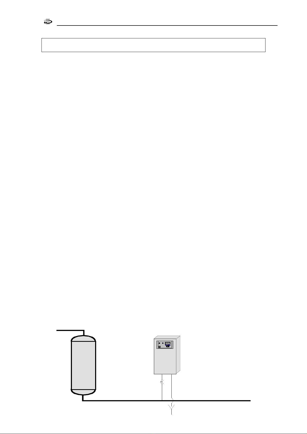
Water softening plant SYCON 3000 H
Analytical Instrument to Measure the Total Hardness of Water
Installation example

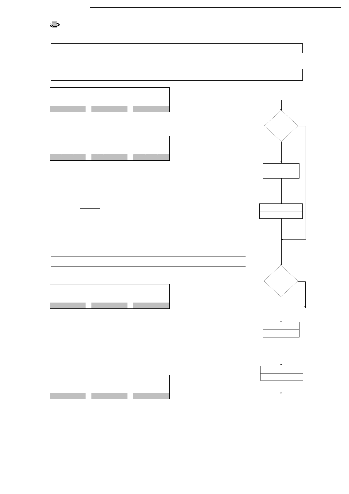
Operating displays
LED control lamps
2
SYCON
3000 H
Operating displays
LED control lamps
Coloured control lamps indicate the most important operating states:
The control lamps "Soft water" and "Hard water" display the result of the last analysis.
During a new analysis, the control lamps "Analysis“ and the lamp displaying the last result (i.e. "Soft
water" or "Hard water") blink.
If both the control lamps "Soft water" and "Hard water" are blinking, no analysis result is a ailable, e.g.
after the instrument has been switched on.
In the e ent of a malfunction or disorder, the control lamp "Fault" blinks.
Additional information can be found on the LCD display.
Analysis (yellow)
Hard water (red)
MT 4A
ON
F1
START FLUSH
10 m 2 *
F2 F3
0.90°mg/l
Limit
> 0.5
KEY
Fuse
Power switch
LED - control lamps LCD - display
Keys
Soft water ( green)
Fault (red)
Operating displays
LCD display
3
SYCON
3000 H
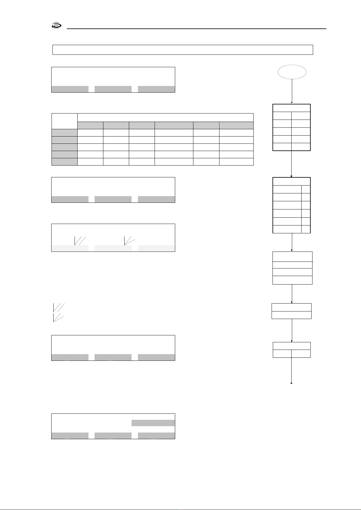
LCD display
Displays between the analyses
9
m
|
5
,
3
1
c
b
m
|
2
*
L
i
m
i
t
2
.
3
p
p
m
>
=
9
.
0
S
T
A
R
T
F
L
U
S
H
In the upper line of the LCD display, the time
remaining until the next analysis is shown on
the left (e.g. 9 minutes). If the instrument has
been programmed accordingly, the flow-rate
olume until the next analysis is also displayed
alongside the time (e.g. 5.31 cbm).
If the display "Stop" is shown instead of the
minute alue, an imminent analysis is delayed
by the acti ated input "STOP".
An analysis can be started manually at any
time.
If, for example, the display 1* appears on the
right in this line, this indicates that, when the
limit alue is next exceeded or fallen short of,
the programmed output function e.g.
"Impulse signal" will be acti ated.
If, for example, the display 2* appears, the
function will only be acti ated after 2 succes-
si e o er/underruns of the limit.
In the middle of the display, the last measured
water hardness is displayed (e.g. 1.1mg/l
CaCO
3
). Values outside the measuring range
are designated by the symbols < and > and
by a specification of the measurement range
limit
(e.g. <0.1 mg/l CaCO
3
).
Next to this, the programmed limit alue ap-
pears with the symbols "<=" for an under run
of this limit and, with the corresponding pro-
gramming, ">=" for an o errun of the limit
alue (e.g. >=1.0 mg/l CaCO
3
).
After the instrument has been switched on, the
alue "----" is displayed until the first meas-
urement.
The lower line gi es information on the possi-
ble functions of the buttons arranged beneath
it (e.g. "START" and "FLUSH").
Displays during the analyses
B
l
a
n
c
v
a
l
u
e
2
s
1
*
L
i
m
i
t
2
.
3
p
p
m
>
=
9
.
0
E
N
D
During an analysis, the phases Flush, Black
alue, Blanc alue, Titration and Wash with
the remaining times are displayed in the upper
line (e.g. Wash 20 seconds).
During the display of the phase ‚Blanc alue’
additionally the photoelectrical alue meas-
ured in the measurement chamber is displayed
in %. If this alue is not in the range between
45% and 115% the measurement chamber
needs to be cleaned or the sensibility of the
electronic needs to be regulated with help of
the potentiometer left of the reagent bottle
(see also calibration page 21).
T
i
t
L
i
m
i
t
2
.
3
p
p
m
>
=
9
.
0
E
N
D
During titration, howe er, the display "Tit" is
shown with two bars alongside it. The lower
bar designates the limit alue of the optical
measurement. The upper bar designates the
current measured alue. As soon as the upper
bar attains the length of the lower bar, the
measured alue is sa ed and, after a short de-
lay, the newly measured water hardness is
then displayed.
Additional displays
I
n
d
i
c
a
t
o
r
r
e
f
i
l
l
P
o
s
s
i
b
l
e
a
n
a
l
y
s
e
s
2
4
H
O
R
N
Different messages or fault indications alter-
nate with the displays between and during the
analyses
(see the section "Messages" on page 6).
Note
With the help of the "KEY" button on the right,
With the help of the "KEY" button on the right, With the help of the "KEY" button on the right,
With the help of the "KEY" button on the right,
fu
fufu
fur
rr
rther fun
ther funther fun
ther functions for the "F3" button can be
ctions for the "F3" button can be ctions for the "F3" button can be
ctions for the "F3" button can be
called up.
called up.called up.
called up.
Operating displays
INFO display
4
SYCON
3000 H
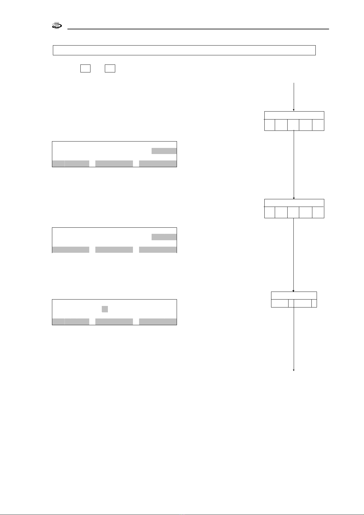
INFO displays
With the help of the INFO key, different information or alues can be requested. Modifications will be
described – as far as possible – in the programme section "Changing and reading out the programme
data". Only the Ser ice telephone number can be altered during the display.
Press the KEY key repeatedly until the key function INFO is displayed for the right-hand key F3.
Press the INFO key. The first information is displayed.
Other information can be obtained by further pressing the INFO key.
9
m
5
,
3
1
c
b
m
2
*
L
i
m
i
t
2
.
3
m
g
/
l
>
=
9
.
0
S
T
A
R
T
I
N
F
O
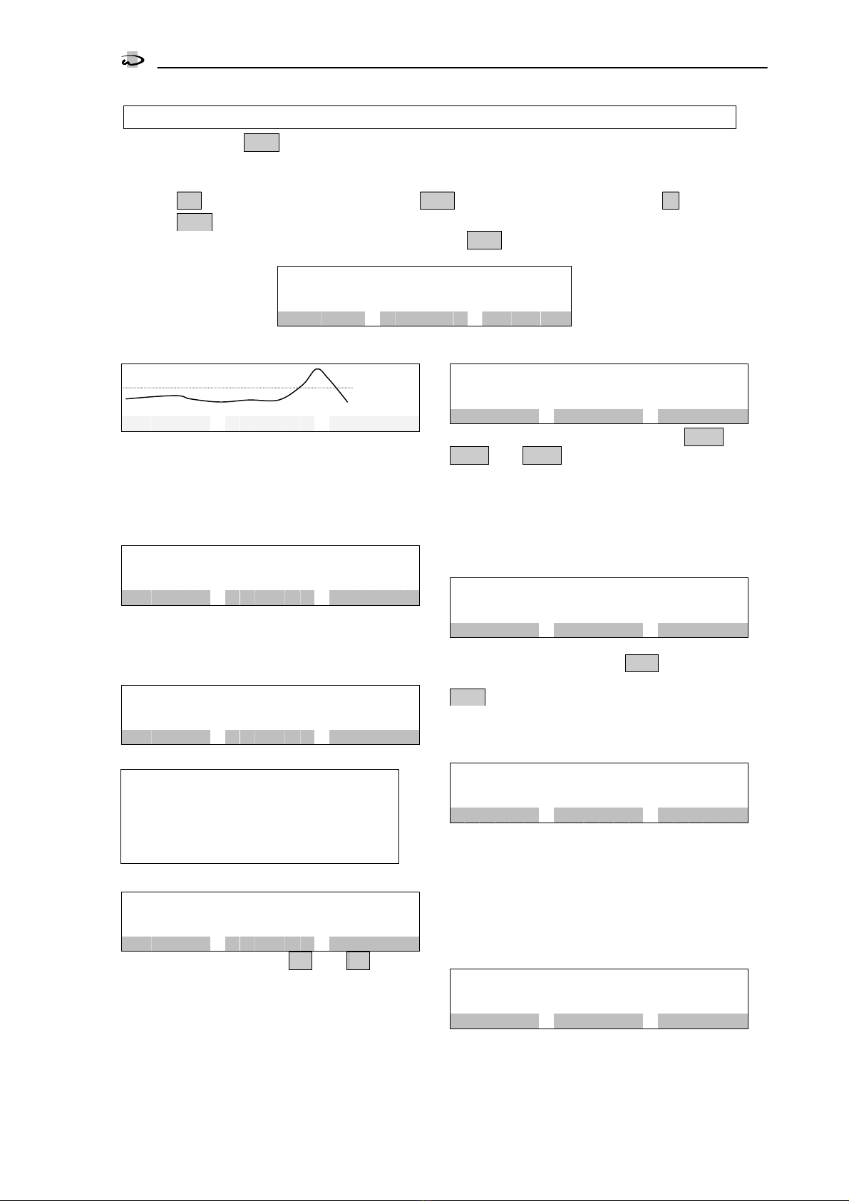
Diagrams
l
i
m
E
N
D
I
N
F
O
The last 100 results of the analysis and the
programmed limit are displayed as diagrams.
So if e.g. a measurement is carried out e ery
10 minutes the results of the last 1000 min-
utes (aprox. 17 hours) are displayed.
Indicator type and hardness unit
I
n
d
i
c
a
t
o
r
H
A
1
,
2
R
a
n
g
e
:
1
.
1
-
2
1
.
3
H
a
r
d
n
e
s
s
u
n
i
t
:
p
p
m
E
N
D
I
N
F
O
The programmed indicator type, the associ-
ated hardness range and the unit of hardness
are displayed.
Service telephone number
S
e
r
v
i
c
e
t
e
l
e
p
h
o
n
n
o
.
0
5
1
2
1
1
2
3
4
5
6
7
8
#
I
N
F
O
The Ser ice telephone number is displayed.
Altering the telephone number:
SELECTING DIGITS:
Press the key with the "
" symbol.
CHANGING DIGITS:
Press the key with the "#
##
#" symbol.
Input states
I
n
p
u
t
s
t
a
t
e
s
S
T
A
R
T
=
-
S
T
O
P
=
-
E
N
D
I
N
F
O
The functions of the inputs IN1 and IN2 with
their current switching states are displayed.
A horizontal line "
-
--
-
" alongside the designation
means: Input not acti e.
A ertical line "|
||
|" alongside the designation
means: Input acti e.
If one of the both inputs is not in use “No In-
put” is displayed.
Output states
O
u
t
p
u
t
s
t
a
t
e
s
P
u
l
s
e
=
-
P
e
r
m
a
n
.
1
=
-
M
e
s
s
a
g
e
=
-
E
N
D
I
N
F
O
Programmed functions of the outputs OUT1,
OUT2 and OUT3 with their current switching
states are displayed.
A horizontal line "
-
--
-
" alongside the designation
means: Output not acti e.
A ertical line "|
||
|" alongside the designation
means: Output acti e.
Analysis result counter
A
n
a
l
y
s
e
s
c
o
u
n
t
e
r
S
O
F
T
:
1
4
3
6
H
A
R
D
:
4
5
E
N
D
I
N
F
O
In the first line the number of all analyses con-
ducted with the result Water SOFT and in the
second line the number with the result Water
HARD is displayed.
The max. number totals 9'999'999. Thereafter,
the counters are reset to zero.
Software status
S
o
f
t
w
a
r
e
v
e
r
s
i
o
n
S
Y
C
O
N
3
0
0
0
H
0
1
0
1
.
2
5
E
N
D
I
N
F
O
The software is continuously ser iced in the fac-
tory. Modifications are made as the need arises
to bring the product in line with new findings and
requirements.
The ersion number and the software imple-
mented are displayed.
Internal measurement and
blank value
I
n
t
e
r
n
a
l
M
e
a
s
u
r
m
.
1
0
1
%
L
a
s
t
b
l
a
n
k
v
a
l
u
e
9
9
%
E
N
D
I
N
F
O
The LED in the measurement chamber is acti ated
and in the first line the current alue of the optical
measurement is displayed (range 0-121%).
In the second line the alue of the last blank
alue is displayed (range 0-121%).

Manual control
5
SYCON
3000 H
Manual control
The three keys F1
F1F1
F1, F2
F2F2
F2 and F3
F3F3
F3 under the display are characterised as softkeys. These keys ha e a
changing function instead of a fixed function. The function that the key has at the moment is shown
abo e the key in the in erse colour scheme in the lower display line. In some operating states, you can
call up further functions for the F3
F3F3
F3 key with the aid of the KEY
KEYKEY
KEY button.
Se eral key functions are triggered after a time delay to prohibit unintended reactions. The running
time delay is highlighted in the third LCD line.
Analysis start
A
T
T
E
N
T
I
O
N
!
A
n
a
l
y
s
i
s
s
t
a
r
t
4
s
e
c
o
n
d
s
S
T
A
R
T
Press the Start key. After 4 seconds a new
analysis sequence begins with a flush opera-
tion.
Attention: A new analysis can also be started
when an error message is displayed.
Start extra flush
A
T
T
E
N
T
I
O
N
!
S
t
a
r
t
e
x
t
r
a
f
l
u
s
h
4
s
e
c
o
n
d
s
F
L
U
S
H
H
It is possible to initiate an additional flushing
process. In so doing, no current alues such
as e.g. the analysis inter al are reset.
An additional flush is terminated again after
10 seconds plus the flush time entered in the
programme step 1.1.
By pressing the "END" key a flush operation is
prematurely aborted.
Warning!
Inadequate flushing can lead to an incorrect
e aluation.
Start servicing
A
T
T
E
N
T
I
O
N
!
S
t
a
r
t
s
e
r
v
i
c
e
4
s
e
c
o
n
d
s
S
E
R
V
Press the "SERV" key. After 4 seconds the ser-
icing phase is initiated. You can recalibrate
the electronics and switch the metering pump
on and off. See also the section Ser ice setting
1 and 2 on page 21.
You switch back to normal operation by press-
ing the "END" key.
Test output relays
A
T
T
E
N
T
I
O
N
!
T
e
s
t
o
u
t
p
u
t
r
e
l
a
y
s
4
s
e
c
o
n
d
s
T
E
S
T
Press the "TEST" key. After 4 seconds the phase Test
Output relays is initiated. You can switch the 3 out-
put relays on and off. see also the section "Testing
the output relays" on page 22..
Acknowledge horn
A
T
T
E
N
T
I
O
N
!
T
r
o
u
b
l
e
b
l
a
n
k
v
a
l
u
e
A
n
a
l
y
s
i
s
s
t
o
p
H
O
R
N
If a message appears in the LCD display and
the integrated signal tone generator sounds at
the same time, the tone can be deleted by
pressing the "HORN" key.
Attention! The display of the message in the
LCD display cannot be deleted. It disappears
automatically as soon as the cause of the
message is remedied or a new analysis has
been started.
End
F
l
u
s
h
L
i
m
i
t
2
.
3
p
p
m
>
=
9
.
0
E
N
D
Whene er the key function "END" is displayed,
the current function can be ended.
Acknowledge relays
A
T
T
E
N
T
I
O
N
!
A
c
k
n
o
w
l
e
d
g
e
P
e
r
m
.
r
e
l
1
A
n
a
l
y
s
i
s
s
t
o
p
R
E
L
A
Y
When the key function "RELAY" is displayed,
one of the following relays can be deleted:
1. Permanent relay 1
2. Permanent relay 2
3. Signal relay
If the "RELAY" key is pressed, the relay con-
cerned is displayed and deleted after 6 sec-
onds.
If the display "Analysis stop" appears, an
analysis must be started by hand.
If programmed accordingly, the start of a new
analysis can also occur by means of an exter-
nal switch.

Messages
6
SYCON
3000 H
Messages
If the integrated buzzer is acti ated in the course of a message, you can delete it by pressing the
"HORN" key. The message in the LCD display is only remo ed when the cause of the message is
remedied or a new analysis is started manually.
You acknowledge an acti ated relay by pressing the "RELAY" key.
In the case of the display "Analysis stop", you must start a new analysis manually. See the section
"Manual control" on page 5.
Refill indicator
I
n
d
i
c
a
t
o
r
r
e
f
i
l
l
P
o
s
s
i
b
l
e
a
n
a
l
y
s
e
s
2
4
H
O
R
N
Indicator must be refilled. On the lower right-
hand side the probable number of possible
analyses is displayed.
As soon as this message is displayed, a certain amount of
indicator is a ailable. As the indicator required per analy-
sis is dependent on the water hardness, the probable
number of analyses cannot be determined exactly in ad-
ance. In calculating the display alue, soft water with a
water hardness of 0.0 ppm CaCO
3
is assumed.
After each analysis this alue is recalculated with the ac-
tual amount of indicator that still remains.
If there is no indicator when the instrument is
switched on, the display "Indicator lack Analy-
sis stop" appears immediately.
Indicator lack analysis stop
A
T
T
E
N
T
I
O
N
!
I
n
d
i
c
a
t
o
r
l
a
c
k
A
n
a
l
y
s
i
s
s
t
o
p
H
O
R
N
Automatically no further analyses are started.
Refill indicator.
Error blank value
A
T
T
E
N
T
I
O
N
!
E
r
r
o
r
b
l
a
n
k
v
a
l
u
e
A
n
a
l
y
s
i
s
s
t
o
p
H
O
R
N
Automatically no further analyses are started.
Possible causes:
Instrument or sample contaminated
No flush occurred
No water inflow
Calibration necessary
Electrical defect (check connector)
Internal measurement too high
A
T
T
E
N
T
I
O
N
!
I
n
t
r
.
m
e
a
s
u
r
.
t
o
o
h
i
g
h
A
n
a
l
y
s
i
s
s
t
o
p
H
O
R
N
Automatically no further analyses are started.
Possible causes:
Indicator has not been metered out
No water inflow
Calibration necessary
Electrical defect (check connector)
Internal measurement too low
A
T
T
E
N
T
I
O
N
!
I
n
t
r
.
m
e
a
s
u
r
e
.
t
o
o
l
o
w
A
n
a
l
y
s
i
s
s
t
o
p
H
O
R
N
Automatically no further analyses are started.
Possible causes:
No water inflow
Calibration necessary
Electrical defect (check connector)
Water hardness over/underrun
A
T
T
E
N
T
I
O
N
!
W
a
t
e
r
h
a
r
d
n
e
s
s
e
x
c
e
e
d
e
d
H
O
R
N
According to the programming in program
step 1.5, the o errunning or under running of
the water hardness is displayed.
Example: Hard water = Limit alue exceeded.
Permanent signal 1
A
T
T
E
N
T
I
O
N
!
P
e
r
m
a
n
e
n
t
s
i
g
n
a
l
1
A
n
a
l
y
s
i
s
s
t
o
p
R
E
L
A
Y
Following an o errun or underrun of the water
hardness (see programming step 1.5), the ac-
ti ation of the relay "Permanent signal 1" is
displayed.
It is also displayed whether an analysis stop
has occurred or whether analyses continue to
be conducted (see program step 6.3).
Permanent signal 2
A
T
T
E
N
T
I
O
N
!
P
e
r
m
a
n
e
n
t
s
i
g
n
a
l
2
A
n
a
l
y
s
i
s
s
t
o
p
R
E
L
A
Y
Following an o errun or under run of the wa-
ter hardness (see program step 1.5), the acti-
ation of the relay "Permanent signal 2" is dis-
played. This relay can be acti ated e en in the
case of a fault according to the programming
in program step 6.7. It is also displayed
whether an analysis stop has occurred or
whether analyses continue to be conducted
(see program step 6.5).

Input functions
7
SYCON
3000 H
Input functions
From the 3 a ailable input functions, maximally 2 can be programmed for the two inputs of the ana-
lyser in the programme steps 3.1 and 3.2 or can be deacti ated totally. Each function can only be
implemented once.
In programme step 3.3, it is determined whether the inputs are to be acti e with open or closed con-
tact.
Start analysis
An analysis of the water can only be started
from this input if the instrument is in the stand-
by position and indicator is a ailable.
In programme step 4.1, a delay time period
can be entered.
Applications: The analysis has to be started
from an extern control station.
Stop analysis
If the input is acti ated, no analyses are initi-
ated by a time inter al, by a olume inter al or
o er the input "Start analysis". Only the man-
ual triggering o er the "START" button is possi-
ble. A running analysis is aborted by a flushing
operation.
In programme step 4.2, a delay time can be
entered.
Once the input is acti ated information are
displayed in the upper left corner of the dis-
play.
Analysis inter al has not ended yet:
Display: "STOP" in change with the display of
the rest time of the inter al
Analysis inter al has ended:
Display: "STOP"
Applic tions:
No n lyses should be conducted in the c se
of w ter short ge or pressure deficiency.
An lyses should only be performed if stor ge
reservoir is filled or if n osmosis system is in
oper tion.
An lyses should only be conducted t cert in
times (extern l timer).
This input is speci lly designed for the using of
flow monitor. Short impulses will be dded to
one impulse.
Ex mple: Using of flow monitor
Progr m step 4.2 = 10 Sec.
An n lysis st rts if the cont ct of the flow moni-
tor is ctiv ted longer then 10 seconds.
An n lysis lso st rts if the cont ct is ctiv ted
5 times for 2 seconds, e.g. if w ter is only
t ken out for short periode of time.
Reset relay
With this input it is possible to clear the relays
of the output functions "Permanent signal 1",
"Permanent signal 2", "Signal relay" and the
built-in signal tone generator from a switch
station.
In programme step 4.3, a delay time can be
entered.
Attention!
The displ y of the mess ge in the LCD displ y
is not deleted. It dis ppe rs utom tic lly s
soon s the c use of the mess ge is removed
or new n lysis h s been st rted.
If the displ y "An lysis stop" ppe rs, n
n lysis must be st rted m nu lly.
With the corresponding progr mming, the st rt
of new n lysis c n lso occur through n
extern l switch (see St rt n lysis).
Water meter
An analysis can also be started after the pas-
sage of a certain olume of water. To this end,
the Water olume 1 and the Water olume 2
are entered in the programme steps 4.4 and
4.5. The Water olume 1 is taken into consid-
eration if, after an analysis, the limit alue has
not been exceeded and the Water olume 2 if
the limit alue has been exceeded. This allows,
after an o errun of the limit alue, the follow-
ing analyses to be executed in shorter inter-
als.
In programme step 4.6, the pulse inter al of
the water meter is entered.
The resetting of the programmed flow rate oc-
curs at each analysis start and is corrected ac-
cording to the Water olume 2 in the e ent of
the limit alue being exceeded.
Note:
In sever l qu ntity-dependent controls for sof-
tening pl nts, flo ting (potenti l-free) rel y
cont ct is v il ble th t simult neously con-
nects to the cont ct of the w ter meter. This
rel y cont ct c n lso be implemented.
A maximum of 3 pulses per second are regis-
tered.

Output functions
8
SYCON
3000 H
Output functions
Of the 5 a ailable output functions, maximally 3 can be programmed for the outputs of the analyser.
The output function "Permanent signal" is a ailable in 2 different ersions. With the output function
"Permanent signal 2" the relay can also be acti ated in the case of a disturbance in function.
The acti ation of the outputs Pulse signal and Permanent signal can occur with hard water or soft wa-
ter according to the programming in programme step 1.5.
In programme step 5.4, it is determined whether the outputs are acti e when the electrical oltage is
switched off or when li e.
Pulse signal
The signal ser es to trigger signal de ices,
programme mechanisms or PLC controls.
The pulse duration can be selected in pro-
gramme step 6.1 between 1 and 999 sec-
onds.
Im programme step 6.2, the number of bad
messages is programmed after which the sig-
nal is acti ated.
Permanent signal 1
The signal ser es to trigger al es, horns or
signal de ices that require a permanent con-
tact after the limit alue o er/underrun.
In programme step 6.3, it is programmed
whether the relay is deacti ated again, if on
the next analysis the result "Water good" oc-
curs, or if no further analyses are to be made.
In this case, a deletion must take place by
hand or ia the input "Reset relay".
In programme step 6.4, the number of bad
messages is programmed after which the sig-
nal is acti ated.
Permanent signal 2
The signal ser es to trigger al es, horns or
signal de ices that require a permanent con-
tact during the limit alue o er/underrun.
The function corresponds to the output func-
tion "Permanent signal 1". Howe er, the output
relay can also be acti ated in the e ent of dis-
turbances in instrument functioning (pro-
gramming 6.7).
A connected shut-off al e is then closed not
only with an o er/underrun of the water hard-
ness, but also in the e ent of a functional dis-
turbance.
In programme step 6.5, it is programmed
whether the relay is deacti ated again, if on
the next analysis the result "Water good" oc-
curs, or if no further analyses are to be made.
In this case, a deletion must take place by
hand or ia the input "Reset relay".
In programme step 6.6, the number of bad
messages is programmed after which the sig-
nal is acti ated.
Analysis active
This output function is acti ated during an
analysis, during the extra flushing and on cali-
bration.
Val es or pumps can be triggered to supply
the analyser with water.
A al e for the cool-water inflow of a cooler
can also be controlled. In order to cool down
the test water initially, the opening of the input
al e in the analyser can be delayed within the
range of 0-999 seconds (programme step
6.8).
Indicator or signal de ices can also be con-
nected to display the analysis process.
Signal relay
In programme step 6.9, it is determined with
which fault messages this relay is acti ated.

Recorder outputs
9
SYCON
3000 H
Recorder outputs
At the recorder outputs RC1 and RC2, line recorders or dot printers with a current input of 0 - 20 mA
or 4-20 mA can be connected. Programming occurs in programme steps 8.1 and 8.2 respecti ely.
Recorder output RC 1
A recorder at this output registers the following states of the analyser:
1. Analysis acti e, ser icing or instrument has been switched on 4. Refill indicator
2. Analysis result: water soft or beneath the limit alue 5. Fault
3. Analysis result: water hard or abo e the limit alue
The indi idual states can be accorded current alues from 0 to 20 mA in programme step 8.1.
After the instrument has been switched on, during an analysis and in the Ser icing setting, the follow-
ing is displayed:
"Analysis acti e".
After each analysis the result "Water soft" or "Water hard" is displayed.
If indicator has to be refilled, the display "Refill indicator" appears instead of the display "Analysis ac-
ti e".
As a collecti e fault the display "Fault" appears.
The following 4 faults are possible: Indicator shortage, blank alue too low, measured alue too high,
measured alue too low. These faults effect an analysis stop, which must be deleted by hand.
Recorder output RC 2
A recorder at this output permanently registers the displayed water hardness. An alteration can only
take place after a new analysis. The display can be scaled as desired. Initial and final alues are laid
down in programme step 8.2.
The displayed current alue is calculated by the following formula with the hardness unit mg/l :
Examples for the initial alues
0 and 4 mA with a final alue of 20 mg/l and 15 mg/l
The lower measurement range limit – according to the limit of the indicator used – is displayed on
switching on the instrument and when the limit has been fallen below (underrun). The upper meas-
urement range limit is displayed when the measurement range is exceeded (o errun) and in the e ent
of a fault.
][][20(
]/[
]/[.
)[ mAvalueinitialmAvalueinitialmA
lmgvaluefinal
lmgvaluehardnmeasured
mAvalueCurrent +−∗=
0
Example diagramme Recorder output RC1und RC2
Analysis
= 4 mA
(RC 1)
2 4 6
Water Soft
= 8 mA
(RC 1)
Water Hard
= 12 mA
(RC 1)
Refill indicator
= 16 mA
(RC 1)
Fault
= 20 mA
(RC 1)
8 10 12 14 16 18 20
Water hardness
(RC 2)
Pow er ON
States = RC 1
Water hardness = RC 2
0 10 mg/l 20 mg/l
0
1
0
m
A
2
0
m
A
0 8 mg/l 16 mg/l
4
m
A
1
2
m
A
2
0
m
A
Changing and calling up the programme data
10
SYCON
3000 H
Changing and calling up the programme data
General information on programming and on entering the national language
On commissioning the analyser is pro-
grammed according to the desired mode of
operation. These programme data can be
changed at a later stage. They are not erased
in the e ent of a power failure.
A change in the programme data should
only be carried out by an authorised spe-
cialist.
Make a note of the programme data in the
blank fields of the following flow diagram
and keep this guide in a safe place for the
operating and ser icing personnel.
If changes are made during an analysis
sequence, the analysis is interrupted and
restarted.
1. Press the " KEY " key as often as necessary
until the function "PROGRM" is displayed
for the "F3" key.
9
m
|
5
,
3
1
c
b
m
|
2
*
L
i
m
i
t
2
.
3
p
p
m
>
=
9
.
0
S
T
A
R
T
F
L
U
S
H
P
R
O
G
R
M
2. Press the "PROGRM" key. If in programme
step 9.1 the question pertaining to a code
number has been answered with Yes, you
must enter a code number with the help of
the "
<
<<
<
"
and "#" keys.
C
o
d
e
n
u
m
b
e
r
*
*
*
*
P
R
O
G
R
M
#
Only after this, press the "PROGRM" key. The
next display appears.
Howe er, if no code number has been pro-
grammed in programme step 9.1, you must
keep the "PROGRM" key pressed for approx. 5
seconds until this display appears.
C
H
A
N
G
E
p
r
o
g
r
a
m
m
/
l
a
n
g
u
a
g
e
P
R
O
G
R
M
L
A
N
G
U
A
E
N
D
3. Should you wish to change the language
of the LCD display, press the "LANGUA"
key.
E
N
G
L
I
S
H
E
F
D
N
l
E
N
D
With the help of the "
" key, mo e the cursor
under the letter representing the country of the
desired language.
4. If you wish to commence the program-
ming, press the "PROGRM" key.
General information on the key fun
General information on the key funGeneral information on the key fun
General information on the key func
cc
ctions:
tions:tions:
tions:
Key
KeyKey
Key
"
""
"
"
""
"
You reach the next programme step.
Key
KeyKey
Key
"
""
"
"
""
"
You mo e backwards step-by-step.
Key
KeyKey
Key
"
""
"
"
""
"
In the case of Yes/No decisions, you answer a
question with YES by using this key to position
the cursor beneath the "Y" for Yes; you answer
NO by positioning the cursor beneath the "N"
for No.
For numerical entries, mo e the cursor under
the digit to be changed.
Key
KeyKey
Key
"
""
"
#
##
#
"
""
"
To change a numerical alue and to toggle
between the displays "
-
--
-
" and " | ".
Key
KeyKey
Key
"
""
"
NEXT
NEXTNEXT
NEXT
"
""
"
To change to the next display in the same pro-
gramme step.
Key
KeyKey
Key
"
""
"
KEY
KEYKEY
KEY
"
""
"
To display an alternati e key function for the
"F3" key.
Key
KeyKey
Key
"
""
"
END
ENDEND
END
"
""
"
The programming mode is exited.
If required, further functions re expl ined t
the individu l progr mme steps.
Attention!
Attention!Attention!
Attention!
The progr mming mode is utom tic lly exited
pprox. 2 minutes fter the l st key oper tion.
Changing and calling up the programme data
Reagents and limit value
11
SYCON
3000 H
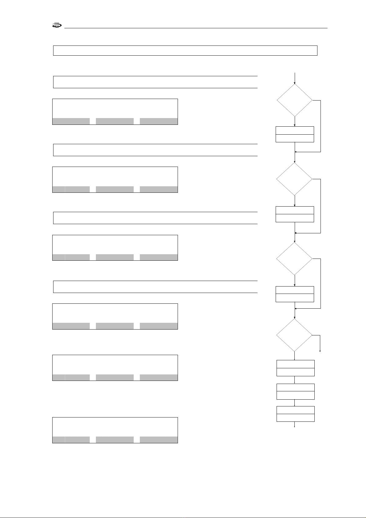
1. Reagents and limit value
Indicator type
Through different indicators,
different measurement
ranges can be determined.
There are 5 indicator types
a ailable. With the help of the "NEXT" key, select the indicator used in the in-
strument.
Measurement rangeIndicator
type °dH °E °F ppm CaCO
3
gpg mmol/Lit.
HA 0,3
0.02 - 0.30
0.02 - 0.37
0.03 - 0.53
0.3 - 5.3 0.02 - 0.31
0.0027-0.0534
HA 1,2
0.06 - 1.20
0.08 - 1.50
0.11 - 2.13
1.1 - 21.3 0.07 - 1.24
0.011 - 0.213
HA 3
0.15 - 3.00
0.19 - 3.75
0.27 - 5.34
2.7 - 53.4 0.16 - 3.12
0.027 - 0.534
HA 30
1.5 - 30.0
1.9 - 37.5
2.7 - 53.4
27 - 534 1.6 - 31.2
0.27 - 5.34
HA 60
3.0 - 60.0
3.8 - 75.0
5.4 - 99.9
54 -999 3.2 - 62.4
0.54 - 9.99
Physical unit of water hardness
Using the "NEXT" key, choose
the unit in which the water
hardness is to be displayed:
°dH, °E, °F, ppm CaCO
3
,
gpg or mmol/ltr.
Correction factor
The displayed alue is influ-
enced by component toler-
ances. Also the chemical
colour reaction is influenced
e.g. by non-hardness-ions. That’s why it may be necessary to adjust the sa ed
absorption diagram to get an optimal result. So it is possible to change the zero
point of the absorption diagram due entering a shift alue (+/- 400 units) and
to change the steepness due entering of a correction factor (0,30 – 2,00).
It is also possible to enter the shift alue automatically with help of a 0° water
sample in step ‘ser ice setting 3’. The correction factor needs to be determined
empirically with help of a known water sample.
shift value: positive value = higher water hardness
correction factor: higher than 1,0 = higher water hardness
Limit value of the water hardness
Determine the alue of the
limit at which a message is to
occur when the water hard-
ness is o er- or underrun (see
programme step 1.5).
Attention:
Attention:Attention:
Attention: The limit alue of the water hardness is dependent on the choice of
the indicator type and the water hardness. Check the limit alue of the water
hardness if you ha e changed programme step 1.1 or 1.2. If a recorder is used,
the scale in programme step 8.2 must also be re-assessed.
Limit value monitoring
It can be laid down whether the signalisation of the
limit monitoring occurs in the e ent of an underrun
= soft water (MIN
MINMIN
MIN) or an o errun = hard water
(MAX
MAXMAX
MAX) of the limit alue.
Example:
In monitoring an ion exchanger, the o errun is selected (MAX
(MAX(MAX
(MAX).
In monitoring a blending facility, the underrun (MIN
(MIN(MIN
(MIN) can be programmed if one wishes to monitor a minimum
water hardness.
S
t
e
p
n
o
.
:
1
.
1
T
y
p
:
H
A
1
,
2
1
.
1
-
2
1
.
3
p
p
m
N
E
X
T
S
t
e
p
n
o
.
:
1
.
2
H
a
r
d
n
e
s
s
u
n
i
t
:
p
p
m
N
E
X
T
S
t
e
p
n
o
.
:
1
.
3
0
°
p
p
m
+
5
0
F
a
c
t
.
1
,
0
0
#
S
t
e
p
n
o
.
:
1
.
4
L
i
m
.
v
a
l
u
e
:
9
.
0
m
g
/
l
#
S
t
e
p
n
o
.
:
1
.
5
L
i
m
.
v
a
l
u
e
:
M
i
n
/
M
a
x
2.1
START
1.5
HA 0,3
1.1
Monitoring
Min Max
HA 1,2
HA 3
HA 30
HA 60
I n dica tor t ype
1.3
Shift value
°dH
°E
°F
ppm CaCO
gpg
Water hardness
3
mmol/ltr
1.2
1.4
Limit value
Correction factor

Changing and calling up the programme data
Analysis sequence
12
SYCON
3000 H
2. Analysis sequence
lush time
S
t
e
p
n
o
.
:
2
.
1
F
l
u
s
h
t
i
m
e
6
0
s
#
Prior to e ery extraction of a test sample, the supply line to the instrument is
flushed. Flush times from 10-999 seconds can be entered.
Analysis interval 1
S
t
e
p
n
o
.
:
2
.
2
A
n
a
l
.
i
n
t
e
r
v
a
l
1
5
m
#
Analyses can be conducted at fixed inter als. Enter an Analysis inter al 1 in the
range from 3 to 9'999 minutes. With the commencement of analysis, the inter-
al timing is restarted.
Attention!
The shortest time between two analyses arises from the rigidly predetermined
analytical cycle, the flush time set in programme step 1.1, the duration of titra-
tion and – insofar as it has been programmed in programme step 6.8 – from
the analysis delay entered.
A new analysis is only started if the pre ious one has been completed. For this
reason, an analysis inter al can be greater than that programmed in this sec-
tion.
Note:
If a water meter is used, a quantity-dependent analytical sequence can also be
selected.
The chronological analytical order is always acti e for reasons of security.
Analyses are not automatically started, howe er, if the input "Analysis stop" is
acti e.
Analysis interval 2
S
t
e
p
n
o
.
:
2
.
3
A
n
a
l
.
i
n
t
e
r
v
a
l
2
3
m
#
If the limit alue is exceeded in an analysis, the inter al time is redetermined with
the Analysis inter al 2 taking into account the time expired. This allows the sub-
sequent analyses to be conducted at shorter time inter als after a limit alue has
been exceeded.
This inter al should therefore be smaller than the Analysis inter al 1. Times in
the range from 3-9'999 minutes can be entered.
2.2
Analysis interval 1
1.4
m
2.1
Flush time
s
3.1
2.3
Analysis interval 2
m
Changing and calling up the programme data
Selection of the programmable input functions
13
SYCON
3000 H
3. Selection of the programmable input functions
From the 4 a ailable input functions, maximally 2 can be programmed to the
two inputs IN1
IN1IN1
IN1 and IN2
IN2IN2
IN2 of the analyser. ATTENTION: Each input function can
only be used once. If one input is not in use so this input should be pro-
grammed to “NoIn". In programme step 3.3, it is determined whether the inputs
are acti e with open or closed contact.
Parameters – such as a response delay – must still be entered for the selected
inputs in programme steps 4.1- 4.5.
A description of the inputs can be found in the chapter Input functions on page
7.
Input: IN 1
S
t
e
p
n
o
.
:
3
.
1
S
t
a
t
S
t
o
p
R
e
s
t
W
a
M
e
N
o
I
n
I
N
P
U
T
1
=
S
t
a
r
t
A
n
a
l
y
s
i
s
Select the desired input function for the input "INPUT 1 (IN1)" with the help of
the "" key.
Stat = Start analysis WaMe = Water Meter
Stop = Stop analysis NoIn = No Input
Rest = Reset relay
Input: IN 2
S
t
e
p
n
o
.
:
3
.
2
S
t
a
t
S
t
o
p
R
e
s
t
W
a
M
e
N
o
I
n
I
N
P
U
T
2
=
S
t
o
p
A
n
a
l
y
s
i
s
Select in accordance with programme step 3.1 the desired input function for the
input "INPUT 2 (IN2)" with the help of the "" key.
Activation of the input functions
S
t
e
p
n
o
.
:
3
.
3
S
T
A
R
T
|
S
T
O
P
|
#
Select the way the inputs are acti ated for the inputs selected in the programme
steps abo e.
Press the "" key to select the input functions programmed for the inputs IN1
and IN2 and the "#" key to choose between "|" or "-".
"|" Acti ation of the selected input function when the contact is closed (NO con-
tact)
"-" Acti ation of the selected input function when the contact is open (NC con-
tact)
If one input was closed with the function "NoIn", so this possibility is not offered.
4.1
3.3
Stat Stop Rest WatM
Input IN 2
3.2
Activation
2.3
3.1
NoIn
Stat Stop Rest WatM
Input IN 1
NoIn
Changing and calling up the programme data
Parameters of the input functions
14
SYCON
3000 H
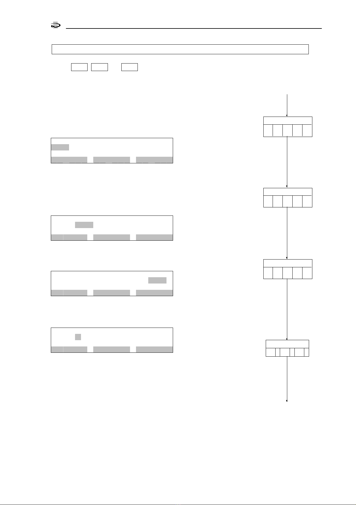
4. Parameters of the input functions
In line with the selection made in programme step 3.1 and 3.2, supplementary
data must be entered in the form of parameters for the inputs IN1
IN1IN1
IN1 and IN2
IN2IN2
IN2.
Input function "START"
Delay time Analysis start
S
t
e
p
n
o
.
:
4
.
1
D
e
l
a
y
s
t
a
r
t
:
7
s
#
Enter for the input function "Start" a delay time in the range of 1 to 99 sec-
onds.
Input function "STOP"
Delay time Analysis stop
S
t
e
p
n
o
.
:
4
.
2
D
e
l
a
y
s
t
o
p
:
3
s
#
Enter for the input "Analysis stop" a delay time in the range of 1 to 99 sec-
onds.
Input function "Reset relay"
Delay time Delete relay
S
t
e
p
n
o
.
:
4
.
3
D
e
l
a
y
r
e
l
a
y
:
3
s
#
Enter for the input "Reset relay" a delay time in the range of 1 to 99 sec-
onds.
Input function "Water meter"
Water volume 1 between the analyses
S
t
e
p
n
o
.
:
4
.
4
W
a
t
e
r
v
o
l
1
1
.
0
0
c
b
m
#
Enter the Water olume 1 after which a new analysis is to be started. You can
programme alues in the range from 0.01 to 650.00 cbm.
Water volume 2 between the analyses
S
t
e
p
n
o
.
:
4
.
5
W
a
t
e
r
v
o
l
2
0
.
1
0
c
b
m
#
After an o errun of the limit alue, the following analysis is started in accor-
dance with Water olume 1 instead of Water olume 2. You can programme
alues in the range from 0.01 to 650.00 cbm.
Pulse interval of the water meter
S
t
e
p
n
o
.
:
4
.
6
W
a
t
e
r
m
e
t
e
r
1
0
0
.
0
L
/
I
#
Enter the pulse train of the water meter. You can enter alues from 0.1 to
5'000.0 Ltr./ Imp.
5.1
Input
Delay
4.1
s
Analysis start
?
Delay
4.2
s
Pulse interval
4.6
L/I
Input
Analysis stop
?
Water volume 1
4.4
cbm
Input
Water
?
Delay
4.3
s
Input
relay
?
3.3
yes
no
yes
no
Reset
yes
no
volume
5.1
no
yes
Water volume 2
4.5
cbm
Changing and calling up the programme data
Selection of the programmable output functions
15
SYCON
3000 H
5. Selection of the programmable output functions
Of the 5 a ailable output functions, maximally 3 can be programmed to the
outputs OUT1
OUT1OUT1
OUT1, OUT2
OUT2OUT2
OUT2 and OUT3
OUT3OUT3
OUT3 of the analyser. The output function "Perma-
nent signal" exists twice (PR1 and PR2). With the output function PR2, the relay
can be acti ated in the e ent of a fault as well as when the preset water hard-
ness is exceeded. In programme step 5.4 it is determined whether the outputs
are acti e when the electrical oltage is switched off or li e.
Parameters – such as the pulse length – must also be entered for the selected
output functions in programme steps 6.1 to 6.11. A description of the outputs
can be found in the chapter Output functions on page 8.
Output: OUT 1
S
t
e
p
n
o
.
:
5
.
1
I
M
P
P
S
1
P
S
2
A
N
A
S
I
G
O
U
T
1
=
P
u
l
s
e
s
i
g
n
a
l
Choose the desired output function for the output OUT1.
Press the INFO key to display the abbre iation in plain text.
IMP = Pulse signal ANA = Analysis is running
PS1 = Permanent signal 1 SIG = Signal relay
PS2 = Permanent signal 2
Output: OUT 2
S
t
e
p
n
o
.
:
5
.
2
I
M
P
P
S
1
P
S
2
A
N
A
S
I
G
O
U
T
2
=
P
e
r
m
a
n
e
.
s
i
g
n
a
l
1
Select according to programme step 5.1 the desired output function for the
output OUT2.
Output: OUT 3
S
t
e
p
n
o
.
:
5
.
3
I
M
P
P
S
1
P
S
2
A
N
A
S
I
G
O
U
T
3
=
S
i
g
n
a
l
r
e
l
a
y
Select the desired output function for the output OUT3 in accordance with pro-
gramme step 5.1.
Activation of the output function
S
t
e
p
n
o
.
:
5
.
4
I
M
P
|
P
S
1
|
S
I
G
-
#
Select the acti ation of the output functions for the outputs selected in pro-
gramme steps 5.1 to 5.3.
"-" Acti ation of the selected output function with relay inoperati e (dropped-
out)
"|" Acti ation of the selected output function with relay operati e (pulled-in).
General note:
In deciding whether e.g. a al e is acti e when li e i.e. open or not, one considers the reaction of
the treatment plant in a current-free state. In such a case no undesired functions should occur in the
plant.
Example flush al e: When the analyser is switched off, a rinse al e must not be open, e en if it is
triggered by an external supply oltage.
Choose a flush al e that opens when carrying oltage and programme "|".
Example fault message: When the analyser has no electrical power, a fault message should occur. Programme "-".
6.1
4.*
5.4
5.2
5.3
IMP
Output: OUT 1
PS1 PS2 ANA SIG
5.1
Activation
IMP
Output: OUT 2
PS1 PS2 ANA SIG
IMP
Output: OUT 3
PS1 PS2 ANA SIG
Changing and calling up the programme data
Parameters of the output functions
16
SYCON
3000 H
6. Parameters of the output functions
In line with the selection made in programme steps 5.1 to 5.3, supplementary data must be entered in the
form of parameters for the outputs OUT 1
OUT 1 OUT 1
OUT 1 to
OUT 3
OUT 3OUT 3
OUT 3.
Output function: Pulse signal
Pulse length
S
t
e
p
n
o
.
:
6
.
1
P
u
l
s
e
l
e
n
g
h
t
1
0
s
#
The length of the pulse signal can be laid down within the range from 1 to 999
seconds.
Number of bad messages
S
t
e
p
n
o
.
:
6
.
2
N
u
m
b
e
r
m
e
s
s
a
g
e
s
1
*
#
You can programme the number of bad messages after which the output func-
tion pulse signal is acti ated. Values from 1 to 5 can be entered. With a alue
greater than 1, when the next analysis occurs is programmed in programme
step 6.10 or 6.11.
Note:
The pulse output is always acti ated as soon as a bad message is displayed after an analysis and
the number of successi e bad messages is the same as or greater than the alue entered in pro-
gramme step 6.2 .
In programme step 1.5, it is determined whether a bad message is to occur if the limit alue is o er-
run or underrun.
Attention!
If the output function "Permanent signal 1" or "Permanent signal 2" is so programmed that the ana-
lyser performs no more analyses before the alue entered in programme step 6.2 is reached, no
further signal can be emitted.
Output function: Permanent signal 1
Acti ation only with a limit o errun or underrun
Automatic delete function 1
S
t
e
p
n
o
.
:
6
.
3
A
u
t
o
m
a
t
.
d
e
l
e
t
e
1
Y
/
N
You can programme whether further analyses are carried out after the acti a-
tion of the output function Permanent signal 1. If further analyses are con-
ducted, the rele ant relay is automatically deacti ated again if the result "Water
good" occurs in one of the next analyses.
If no further analyses are conducted, the relay must be deleted by hand or ia
the input "Delete relay". Moreo er, an analysis must be restarted.
Automatic deletion Yes
YesYes
Yes: Consecuti e analyses e en after a bad message
Automatic deletion No
NoNo
No: Analysis stop in the e ent of a bad message
Number of the bad messages
S
t
e
p
n
o
.
:
6
.
4
N
u
m
b
e
r
m
e
s
s
a
g
e
s
2
*
#
You can programme the number of bad messages (limit o erruns/underruns)
after which the output function is acti ated. Values from 1 to 5 can be entered.
With a alue greater than 1, it is laid down in programme step 6.9 or 6.10
when the next analysis occurs.
6.5
Output
Pulse lenght
6.1
s
Pulse signal
?
Autom.delete1
6.4
Output
Permanent
signal 1
6.3
5.4
no
yes
no
?
yes
Yes No
Bad messages
6.2
*
6.5
Bad messages
*
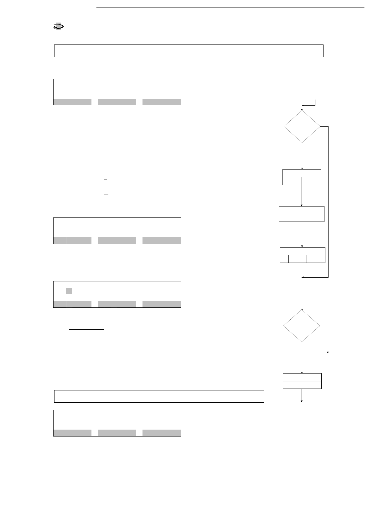
Changing and calling up the programme data
Parameters of the output functions
17
SYCON
3000 H
Output functions: Permanent signal 2
Acti ation with a limit o errun or underrun and in the e ent of a fault.
Automatic delete function 2
S
t
e
p
n
o
.
:
6
.
5
A
u
t
o
m
a
t
.
d
e
l
e
t
e
2
Y
/
N
You can programme whether further analyses are carried out after the acti ation
of the output relay due to the limit o er-/underrun or the faults programmed in
programme step 6.7. If further analyses are conducted, the relay is automati-
cally deacti ated again if the result "Water good" occurs in one of the next
analyses.
If no further analyses are conducted, the relay must be deleted by hand or ia
the input "Delete relay". Moreo er, an analysis must be restarted.
Automatic deletion Yes: Consecuti e analyses e en after a limit
o er/underrun or fault
Automatic deletion No: Analysis stop in the e ent of a limit o er/underrun
or fault
Number of the bad messages
S
t
e
p
n
o
.
:
6
.
6
N
u
m
b
e
r
m
e
s
s
a
g
e
s
2
*
#
You can programme the number of bad messages (limit o erruns/underruns)
after which the output function is acti ated. Values from 1 to 5 can be entered.
Activation through a fault
S
t
e
p
n
o
.
:
6
.
7
R
F
|
N
I
|
B
V
|
V
H
|
V
L
|
F
a
u
l
t
f
i
l
l
i
n
d
i
A
C
T
I
V
#
As opposed to the output function "Permanent signal 1", you can determine with
the output function "Permanent signal 2" which faults cause the relay to be acti-
ated in addition to the limit o er/underrun.
Using the "#
##
#" key, choose between the display "-" and "|".
"-" = No acti ation through displayed fault
"|" = Acti ation through displayed fault
RF = Refill indicator VH = Measured value too high
NI = No indicator (Stop) VL = Measured value too low
BV = Blank value too low
Output function: Analysis is running
Analysis delay
S
t
e
p
n
o
.
:
6
.
8
A
n
a
l
y
s
i
s
d
e
l
a
y
5
s
#
The start of an analysis – opening of the input al e – can be delayed within the
range of 0-999 seconds.
6.9
Output
Bad messages
6.6
*
Permanent
signal 2
Output
Analysis runs
6.2
no
yes
no
?
yes
6.9
6.4
?
Fault messages
6.7
RF NI BV VH VL
Autom.delete 2
6.5
Yes No
Delay
6.8
s
Table of contents
Popular Analytical Instrument manuals by other brands


Leica
Leica DISTO A2 user manual

PRAGMATIC COMMUNICATIONS SYSTEMS
PRAGMATIC COMMUNICATIONS SYSTEMS HazCam Quick user guide

RS PRO
RS PRO 2.4" Recording Inspection Camera user guide

BIOPAC Systems, Inc.
BIOPAC Systems, Inc. MP150 Troubleshooting

Rothenberger
Rothenberger ROSCOPE mini Instructions for use

USBDÜSEN
USBDÜSEN NOZZCAM operating instructions


