CUES PICS Manual

PICS
OPERATION & MAINTENANCE MANUAL
P/N CH915, Revision: 091520
Pullback Inspection Camera System
CUES
Gas Infrastructure repair, rehabilitation, and replacement
> Ulity Locang
> Data Management
> Lateral Ulity Inspecon
> HDD Bore Hole Inspecon

TABLE OF CONTENTES
II CUES Inc.,PICS User Manual | CH915 www.cuesinc.com,| salesinfo@cuesinc.com
CHAPTER - Introduction
PICS System Introduction .................................................
CHAPTER - Equipment Overview
Equipment Overview .........................................................
CHAPTER - System Setup & Installation
Electrical & Physical Connections......................................
Installing the Self Upright Mini Camera and
Centering Ball On The PICS ...............................................
Adjusting the Handle Height ..............................................
Adjusting the Cable Guide..................................................
Installing the Debris Bag ....................................................
Installing the Accessory Bag ..............................................
Installing the Control Unit ..................................................
Installing the Sunshade......................................................
Installing the Pullback Carrier ............................................
Connecting the Coiler to the PCU......................................
Conguring the Coiler and Push Cable...............................
CHAPTER - Operating the System
Operation & Maintenance Instructions...............................
Auxilliary Connections........................................................
Line Trace ..........................................................................
Brake Tension ....................................................................
System Interface ..............................................................
DVR Controls Diagram .......................................................
Keypad Functions ..............................................................
DPad Controls Diagram and Functions...............................
Digital Video Recorder Instructions .....................................
Qwerty Keyboard Instructions ...........................................
Main System Menu Functions............................................
System Menu.....................................................................
Advanced Conguration.....................................................

TABLE OF CONTENTS
CUES Inc.,PICS User Manual | CH915 III
CHAPTER - Operating the System... continued
Granite Mode.....................................................................
System Status ...................................................................
MPT Status .......................................................................
Copyright...........................................................................
Precongured Text Writing Screens...................................
Other Codes ......................................................................
CUES Base Codes .............................................................
CHAPTER - BOMs & Drawings
BOMs and Drawings ...........................................................TBD
APPENDICES
Appendix A - List of Status Messages ................................
Appendix B - PICS Field Firmware Updates ........................
Warranty Information..........................................................
CUES Material Return Policy..............................................
CUES Parts & Service ........................................................
Record of Revisions............................................................

FYI
IV CUES Inc.,PICS User Manual | CH915 www.cuesinc.com,| salesinfo@cuesinc.com
® equipment is designed to be easy to use during day to day operation. However, it is powered
electrically and thus must be operated with care and safety. PLEASE READ THE INFORMATION ON SAFETY AND
MAINTENANCE EVEN IF THE SYSTEM IS SET UP BY SOMEONE ELSE.
Care was taken in the design of this product and in the production of this document and related materials. However,
® makes no warranty for the use of its products and assumes no responsibility for any errors or omissions
in this document or for incidental or consequential damages resulting from the use of the products or the information
contained in this document. Specications may change without notice.
All rights are reserved. No part of this publication may be reproduced, stored in any information system, or transmitted
by any means, manual, electronic, or mechanical without the prior written permission of ® .
We would be pleased to hear from you. If you see any errors or desirable extensions or improvements, please write
us at the following address, C/O Operator’s Manuals: ® Corporate Oce Rio Vista Avenue
Orlando, Florida
Copyright © ®
All rights reserved. No part of this publication covered by the copyright hereon may be reproduced or used in any
form by any means - graphic, electronic, or mechanical, including photocopying, recording, taping, or information
storage and retrieval systems - without the expressed written permission of ®.
Violators will be prosecuted.
Styles and specications are subject to change without notice. First version published in .
Printed in the United States of America.
® toll free hot line for
Customer Service and ordering parts:
--CUES (--)
CUES ® Canada
Sismet Rd.,
Mississauga, Ontario
Canada LW P
--
-- FAX
AM - PM EST M-Fri
More locations to serve you!
CUES West
S. Augusta Ct.
Ontario, CA
--
-- FAX
AM - PM PST M-Fri
CUES ® Corporate Oce
Rio Vista Avenue
Orlando, Florida
--
-- FAX
am - pm EST M-Fri
CUES ® Atlanta
Industrial Ct.
NW, Suite
Suwannee, GA
--
-- FAX
am - pm EST M-Fri
CUES ® Northern California
Eubanks Court, Suite C
Vacaville, CA
Phone: --CUES
Fax: --
:AM - PM PST M-Fri
CUES ® MidWest
Parklawn Drive, Suite K
Waukesha, WI
Phone:: --
Fax: --
AM – PM CST M-Fri
CUES Northwest
NW Commerce Ct., Suite B
Estacada, OR
Phone: ... ext:
Fax: --

1
CUES Inc.,PICS User Manual | CH915
INTRODUCTION
This manual includes setup, operation, troubleshooting, and maintenance instructions for the CUES PICS
Pullback Inspection Camera System. Equipment information is included in the Equipment Overview chapter
in this manual. The instructions in this manual are for the PICS system and its components only.
The PICS system is designed to inspect HDD boreholes and pre/post inspections of sanitary and storm
service laterals. The system operates as a stand-alone system, but is also fully compatible with external
observation software or other asset management systems. An optional mainline interface is available for
operation with standard CUES TV trucks. The PICS system can be powered from the built-in, rechargeable
battery, AC mains power, or VDC power. If uncertain about your specic system or need more
information regarding the PICS, please call our Customer Service Department at ---.
The CUES PICS is designed to:
• Operate as an All-In-One system or the modular design allows the control unit to be removed and used
separately or to accommodate compact storage.
• Operate with a standard TV inspection system (optional).
• The standard conguration reel will operate/store up to ’ of berglass rod push cable (optional)
optimized for pullback inspection applications.
• Operate in extreme conditions with the heavy duty construction and weather / water resistant, injection-
molded control unit.
• Designed to operate with a borehole centering and leveling carrier for .” to ” boreholes.

2
CUES Inc.,PICS User Manual | CH915 www.cuesinc.com,| salesinfo@cuesinc.com
EQUIPMENT OVERVIEW
PICS SYSTEM

2
CUES Inc., PICS User Manual | CH915
EQUIPMENT OVERVIEW
The PICS System consists of the following equipment. Refer to the BOMs and drawings at the
back of this manual for additional information.
PICS SYSTEM
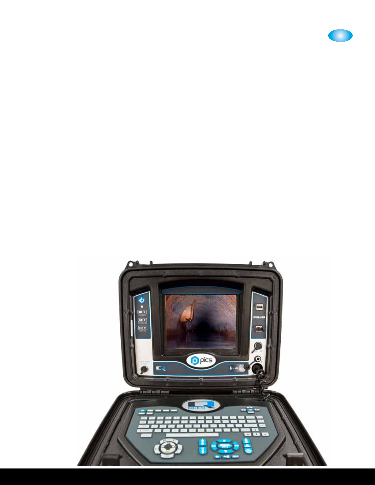
(CH) CONTROL UNIT WITH TEXT WRITING,OBSERVATION CODING, DIGITAL RECORDING
AND INDUSTRIAL GRADE MONITOR IN AN INJECTION MOLDED ENCLOSURE TO INCLUDE:
• .” industrial grade, optically bonded, sunlight viewable, monitor with anti-reective
properties and LED backlighting
• Operator Interface with controls for all camera functions
• Video Titling to include multiple predened and customizable screens
• Digital video recording features video recording and playback and records screenshot
picture images
• Control Unit quick bracket mount for attaching to the coiler with hands free locking
• System Interface connector features Video, Audio, distance counter quadrature and
VDC outputs and a Video input
• Built-in Li-Ion Battery with advanced charging technology for hours of continuous use
• Universal AC power input - volt AC, / Hz, or Volt DC Power Source
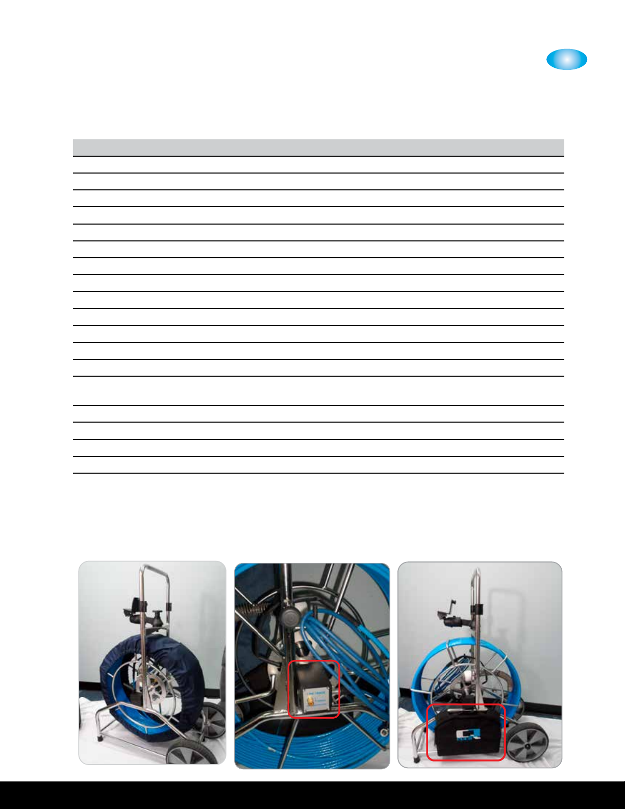
(CH) STAINLESS STEEL COILER TO INCLUDE:
• Heavy gauge and corrosion resistance Stainless Steel construction
• Adjustable height handle for portability with cam locks and button stops
• Large ” durable wheels for portability and a balanced footprint for stability
• Quick-Connect allows Control Unit mounting with axes adjustability
• Adjustable coiler brake
• Integral distance sensor
(CH-xx) . Diameter Fiberglass Rod and Hytrel jacket Push Cable to include:
• Push Cable with durable Hytrel jacket and advanced berglass rod
(CH) Pullback centering and leveling carrier to include:
• Pullback centering and leveling carrier
(CH) ACCESSORY KIT TO INCLUDE:
• Sunshield for enhanced sunlight viewability
• ft interconnect cable for connecting the coiler to the control unit
• AC power cord for - volt AC, / Hz, operation
(SR) SELF-LEVELING COLOR CAMERA WITH BUILT-IN SONDE, NTSC TO INCLUDE:
• /” Stainless Steel Camera head designed for HDD borehole inspections
• Hz integral sonde
• high intensity LED’s

2
CUES Inc.,PICS User Manual | CH915 www.cuesinc.com,| salesinfo@cuesinc.com
EQUIPMENT OVERVIEW
Sun Shade
PICS SYSTEM CONTINUED
SYSTEM WEIGHTS - STANDARD PICS CONFIGURATION
CH, COILER WEIGHT MINUS PUSH CABLE LBS.
CH, CONTROL UNIT CASE WEIGHT LBS.
CH - xx, FOOT PUSH CABLE WEIGHT . LBS.
SR SERIES, SELF-UPRIGHT CAMERA . LBS.
CH, ACCESSORY KIT LBS. (not shown)
CH, PULLBACK CENTERING AND LEVELING CARRIER LBS.

2
CUES Inc., PICS User Manual | CH915
EQUIPMENT OVERVIEW
PICS oers a variety of optional equipment to expand the role of the system.
Debris Bag
Line Trace
DESCRIPTION PART NUMBER
PICS (ft Cable)
PICS (ft Cable)
PICS (ft Cable)
PICS (ft Cable)
HDD Borehole Pullback Centering and Leveling Carrier CH
Accessory bag for storage, attaches to coiler frame CH
Debris Bag for push cable coiler basket CH
Prototek Digital Receiver, Hz MS
Prototek Digital Receiver, Hz / Hz / kHz / kHz / kHz / kHz MS
Prototek Analog Receiver, Hz MS
Line-Trace Post Terminal for Line Locating CH
Prototek Buzz Box Sonde Transmitter for Line-Trace Post Terminal, /// kHz MS
PICS Control Unit with digital wireless video transmission kit CH-
Truck Digital . GHz Wireless Video Receiver kit to work with wireless PICS
(CH-) option
TR
Cable to operate PICS with Multi Conductor Truck system CH
Granite-Net Translator with video and footage counter interface CH
Granite Net Basic Decision Support Software GN
Granite Net Advanced Decision Support Software GN
PICS SYSTEM OPTIONAL EQUIPMENT

3
CUES Inc.,PICS User Manual | CH915 www.cuesinc.com,| salesinfo@cuesinc.com
SET-UP & INSTALLATION
ELECTRICAL & PHYSICAL CONNECTIONS -
To reduce the risk of equipment damage, please read the following instructions prior to operating the
system. Ensure that all of the equipment is turned to the OFF (O) position prior to connecting the PICS
system. Inspect all of the cables and connectors for cuts or worn areas prior to operating the equipment.
Repair or replace worn cables immediately.
PROCEDURE: Connecting the System
Power Source:
The PICS can be powered from the built-in, rechargeable battery, AC mains power, or VDC power.
If the internal battery is not going to be utilized, connect the unit to one of the external power sources
listed above.
Camera Centering Ball:
Ensure the centering ball, if needed, is attached to the mini camera as shown in this chapter.
Mini-Camera:
Ensure the mini-camera is connected and secured to the CX- cable end as shown in this chapter.
Adjustable Handle Height:
The PICS includes a height-adjustable handle for portability with cam locks and button stops. Refer to
the handle height adjustment instructions in this chapter.
Debris Bag:
An optional debris bag is provided to prevent debris from spilling/leaking out during and after the inspection.
Ensure the debris bag is attached to the PICS per the instructions in this chapter.
Adjustable Cable Guide: Ensure the push cable is inserted through the cable guide for the most ecient
operation.
Accessory Bag:
An optional accessory bag is available to store additional items, as needed. Ensure the accessory bag is
attached to the PICS per the instructions in this chapter.
Monitor:
Ensure that the Control Unit cable is connected as shown in this chapter.
Power Control Unit (PCU):
The PICS system is controlled by the PCU (power control unit). The PCU contains all of the controls for
the system including system power, camera, lightring, recording, video titling, and observation coding.
Ensure that the PCU is connected as shown.
To adjust the Control Unit position, perform the following:
Swivel/rotate the PCU vertically and left-to-right to place the unit in diering viewing angles. Once the
desired position is determined, secure the unit by turning the hand knobs.

3
CUES Inc., PICS User Manual | CH915
SET-UP & INSTALLATION
Centering Ball, () Pieces, P/N LM
Self Upright Camera P/N SR
To install the self upright camera and centering ball on the
PICS, perform the following:
Remove the orange cap that is covering the end of the CX-
connector as shown.
INSTALLING THE SELF UPRIGHT MINI CAMERA AND CENTERING BALL -

3
CUES Inc.,PICS User Manual | CH915 www.cuesinc.com,| salesinfo@cuesinc.com
SET-UP & INSTALLATION
INSTALLING THE SELF UPRIGHT MINI
CAMERA AND CENTERING BALL -
Slide the bottom piece of the centering ball onto
the end of the CX- connector as shown.
Secure the mini camera to the end of the CX-
connector as shown.
Place the top piece of the centering ball onto the
camera as shown.
Twist the top and bottom pieces of the centering
ball together until secure.

3
CUES Inc., PICS User Manual | CH915
SET-UP & INSTALLATION
ADJUSTING THE HANDLE HEIGHT -
The PICS includes a height-adjustable handle for
portability with cam locks and button stops.
To adjust the height of the handle, open the cam
locks on each side of the handle.
Extend/retract the handle to the desired
position.
To secure, engage the cam locks on both sides
of the handle as shown.

3
CUES Inc.,PICS User Manual | CH915 www.cuesinc.com,| salesinfo@cuesinc.com
SET-UP & INSTALLATION
ADJUSTING THE CABLE GUIDE -
An adjustable cable guide is provided to guide the cable while being released / retrieved
from the coiler.
The cable guide is set at the factory, but can be adjusted based on your specic needs.
To adjust the cable guide, loosen the bolt located on the coiler, then adjust the cable
guide height up/down. Secure the bolt to hold into place.
Replacement cable guides, P/N CH, are available, if needed.
Cable Guide, P/N CH

3
CUES Inc., PICS User Manual | CH915
SET-UP & INSTALLATION
INSTALLING THE DEBRIS BAG -
An optional debris bag is provided to prevent
debris from spilling/leaking out during and after
the inspection.
To attach the debris bag, perform the following:
Wrap the bag around the coiler / cable as shown
below.
Continue wrapping around the coiler and then
loop it through the bottom of the unit.
Attach the velcro ends together to secure in
place.

3
CUES Inc.,PICS User Manual | CH915 www.cuesinc.com,| salesinfo@cuesinc.com
SET-UP & INSTALLATION
INSTALLING THE ACCESSORY BAG -
An accessory bag is provided to store
additional items, if needed. It also includes
a convenient carry handle for portability.
To attach/remove the bag, secure the ()
velcro aps onto the cable reel as shown
and per below:
Secure the long ap at the bottom of the
bag around the bottom of the coiler as
shown.
Then wrap the () smaller aps around the
colier.
Press together to ensure good adhesion.
() velcro aps located on the accessory
bag

3
CUES Inc., PICS User Manual | CH915
SET-UP & INSTALLATION
INSTALLING THE CONTROL UNIT -
The control unit can be quickly installed/removed for o road/remote jobsites or to
accommodate compact storage.The Control Unit features a quick connect mount for attaching
to the coiler. The quick-connect “click-lock” feature is a no-hand locking mechanism for
simple and secure mounting.
To install the control unit,
slide it onto the mounting
bracket as shown. Once
installed, the bracket will
make a clicking sound,
which means the unit is
locked in place.
To remove/release the
control unit, pull the
locking pin while
simultaneously lifting
up on the control unit.
LOCKING PIN

3
CUES Inc.,PICS User Manual | CH915 www.cuesinc.com,| salesinfo@cuesinc.com
SET-UP & INSTALLATION
INSTALLING THE CONTROL UNIT -
Once installed, the control unit can swivel
vertically approximately degrees, and rotate
left-to-right approximately degrees for
dierent viewing angles.
To change the angle of the control unit,
release the hand knob located on the ball
mount. Swivel/rotate the unit vertically and
left-to-right to place the unit in diering
viewing angles. Once the desired position is
determined, secure the unit by turning the
hand knobs.

3
CUES Inc., PICS User Manual | CH915
SET-UP & INSTALLATION
INSTALLING THE SUNSHADE -
A removable sunshade is provided for
optimum visibility in extreme sunlight
conditions.
To install the sunshade, ensure the
magnetic ap is attached at the top of
the LCD screen and place the sunshade
on the control unit as shown.

3
CUES Inc.,PICS User Manual | CH915 www.cuesinc.com,| salesinfo@cuesinc.com
SET-UP & INSTALLATION
INSTALLING THE PULLBACK CARRIER -
To install the pullback and centering carrier on the PICS, perform the following:
Refer to the three components of the pullback and center carrier shown below.
PICS Camera Carrier
PICS Reective Tow Cap
PICS Camera Assembly
Ensure that the front of the carrier, the PICS Reective Tow Cap, is securely attached
to the center of the carrier, the PICS Camera Carrier, as shown below.
Other manuals for PICS
1
This manual suits for next models
1
Table of contents
Other CUES Analytical Instrument manuals