RM Italy HLA 150 User manual

Amplificatore Lineare HF Professionale
HF Professional Linear Amplifier
HLA 150
Commutatore per la selezione della frequenza "banda" di lavoro o per la selezione
automatica gestita dal processore interno - Commutator to select the working
"band" frequency or for an automatic selection from the inner processor.
Indicatore della frequenza impostata o, se il commutatore é in AUT., indica la
frequenza attualmente utilizzata - Selected frequency indicator, when commutator
is in AUT. it indicate the currently used frequency.
Strumento indicatore della potenza d'uscita - Output power wattmeter
Indicatore di stato di protezione - Protection state indicator
Interruttore accensione lineare - Linear amplifier switch
Led indicatore d'accensione lineare - Amplifier switching on led indicator
Commutatore disinserimento attenuatore d'ingresso -Input damper switch
Indicatore attenuatore d'ingresso disinserito - Imput damper switch-off Led
}Commutatore inserimento ritardo SSB - SSB delay switch
~Led indicatore di trasmissione - Transmission led indicator
+/$
3URWHFWLRQ
:DUQLQJ
+)3URIHVVLRQDO/LQHDU$PSOLILHU
$87
W
U
H
Z
R
3
)UHTXHQF\VHOHFWLRQ
S
X
2
X
W
2))
21 +, 7;
2))
66%GHOD\
H
HHHH~
H
}
Frequenza - Frequency : 1,8 - 30 MHz
: 10 - 160 meter
Alimentazione - Supply : 13 Vcc ± 1 V
Assorbimento Max - Max Input energy : 24 A
Potenza d'ingresso - Input power : 1 - 10 W AM - FM
: 1 - 15 W SSB - CW
Potenza d'uscita RF - Output power : 150 W Max AM-FM
: 250 W Max SSB-CW
ROS ingresso - Input SWR : 1.1/1.5
ROS Massimo in antenna - Antenna SWR Max : 2.5
Funzionamento - Mode : All MODE
Fusibile - Fuse : 2 x 12 A
I
Descrizione
L'amplificatore lineare HLA 150 è appositamente studiato per chi ha la necessità di
elevare la potenza in antenna degli apparati decametrici a bassa potenza (tipo Yaesu FT 817,
Icom IC 703 ecc.) mantenendo elevate le caratteristiche di attenuazione delle emissioni
indesiderate (spurie ed armoniche) per effettuare collegamenti a lunga e lunghissima distanza.
Opera in tutte le bande radioamatoriali da 160 (1,8 MHz) a 10 (29,5 MHz) metri in tutti i modi
operativi.
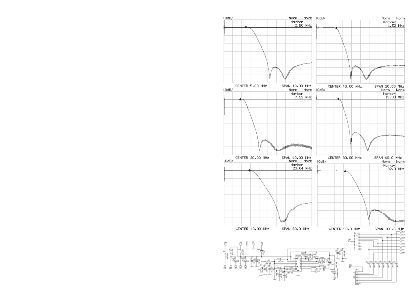
Possiede al suo interno una serie di sei filtri passa-basso con frequenza di taglio di 3/4,5/8/15/
22/31 MHz per abbattere drasticamente le emissioni di armoniche. Il controllo della selezione
del filtro può essere o automatica (posizione AUT. del commutatore 1), controllata tramite un
microprocessore che legge la frequenza di trasmissione e seleziona automaticamente il filtro
appropriato, o manuale (selezione della banda tramite il commutatore 1), in questo caso il
microprocessore controlla che la selezione del filtro sia corretta, eventualmente segnala tramite
un segnale acustico la possibilità che il filtro impostato sia incorretto.
Un circuito di protezione da eccessivo ROS provvede ad interdire il funzionamento dell'ampli-
ficatore in caso che il livello di onde stazionarie in antenna sia eccessivo per il corretto
funzionamento, lo stesso circuito protegge lo stadio di amplificazione dalla possibilità che un'
incorretta impostazione dei filtri passa-basso lo possano danneggiare.
Il modello HLA 150 V ha installate sul dissipatore due ventole per dissipare con maggior
efficienza il calore prodotto permettendone l'uso con temperature ambientali più alte o
permettendo un uso più intensivo (contest ecc.). Le ventole funzionano a velocità variabile per
ridurre la rumorosità in ricezione quando il loro uso è meno necessario.
INSTALLAZIONE
Dopo aver tolto l'amplificatore dal suo imballo ed aver controllato che non abbia subito
danni durante il trasporto, collegare, con una prolunga di RG58 lunga circa 90 cm., il
ricetrasmettitore al connettore SO239 siglato con RTX e l'antenna al connettore ANT posti
entrambi sul lato posteriore dell'amplificatore, assicurarsi che l'interruttore di accensione (5) sia
in posizione OFF, collegare i cavi di alimentazione alla batteria del veicolo o, se l'utilizzo è in
stazione base, ad un alimentatore che sia in grado di fornire 13,5 V con almeno 25 A in modo
continuo. I cavi di alimentazione devono essere di sezione non inferiore a 4 mm² o 12 AWG e
di lunghezza non superiore a 3 m. La tensione non deve superare in nessun caso i 16 V.
Appendice A
Filter 160m
Filter 40m
Filter 80m
Filter 30-20m
Filter 17-15m Filter 12-10m

Posizionare sempre l'amplificatore in modo da poter accedere con facilità a tutti i comandi
avendo cura di lasciare spazio intorno ad esso per permettere una buona ventilazione.
ATTENZIONE !!!
Prima dell'utilizzo dell'amplificatore per i collegamenti radio verificare che antenna e
alimentazione abbiano caratteristiche adeguate.
USO
Accendere l'amplificatore tramite l'apposito interruttore (5), posizione ON, si noterà l'accensio-
ne dell'indicatore verde 6.
Posizionare i comandi come è necessario considerando che:
Il deviatore 7inserisce o disinserisce l'attenuatore d'ingresso, se l'attenuatore è
disinserito si accende l'indicatore 8. L'attenuatore varia di circa 3 dB il livello di potenza di
pilotaggio dello stadio di potenza permettendo di migliorare la resa dell'amplificatore anche con
bassi livelli di potenza in ingresso. In caso il segnale in ingresso sia superiore ad 8 W (12 PEP)
è necessario l'uso dell'attenuatore.
L'interruttore 9vieneusatosolosenonvieneutilizzatounodegliingressidicommutazione
posti nella parte posteriore dell'amplificatore, se si usa il segnale di trasmissione presente
all'uscita del ricetrasmettitore (modo consigliato) l'interruttore 9deve essere in posizione OFF.
Se si usa il circuito VOX all'interno dell'amplificatore la posizione dell'interruttore 9dipende dal
modo di trasmissione, trasmettendo in AM o FM usare la posizione OFF, se si trasmette in SSB
o CW usare la posizione SSB. La posizione in SSB delay di 9inserisce un ritardi di circa 1 sec.
al rilascio del relè di commutazione impedendo il continuo ritorno a riposo dello stesso in
presenza di modulazione impulsiva.
Il commutatore di frequenza (1) deve essere posto o sulla banda appropriata di utilizzo
(accensione del LED corrispondente sull'indicatore 2) o nella posizione AUT. (accensione del
LED giallo su 2).
Se viene selezionata una banda sbagliata quando si commuta in trasmissione si verificano due
condizioni, se la frequenza è inferiore a quella selezionata il microprocessore avvisa con un
segnale acustico l'errore per circa 2 secondi lasciando in funzione l'amplificatore (i filtri sono
dei passa-basso, se si usa un filtro con una frequenza di taglio eccessiva si rischia che venga
emessa una o più armoniche della frequenza di trasmissione, ciò comunque non danneggia
l'amplificatore), se la frequenza di trasmissione è maggiore interviene il circuito di protezione
dell'amplificatore (accensione del LED rosso 4) impedendo la commutazione in trasmissione,
se lo spostamento della frequenza non è eccessivo (condizione non pericolosa per lo stadio di
potenza) interviene solo il microprocessore segnalando continuamente con un suono
intermittente la pericolosità dell'uso in quelle condizioni.
Gli allarmi sonori cessano al ritorno in ricezione del ricetrasmettitore, l'intervento della prote-
relay is disconnected to avoid the return to stand by of the relay in presence of an impulsive
modulation.
The frequency commutator (1) has to be placed either on the appropriate working band
(lighting of the corresponding LED on indicator 2), or on AUT ( lighting of yellow LED on 2).
When a wrong band is selected when commuting under transmission two conditions can
occur:
- When the frequency is lower than the selected one the microprocessor give notice of the
error with a 2 second long acoustic signal, while the Amplifier is working ( the filter are low
pass type therefore if you use a filter with a too high cutting frequency it may be possible
that one or more harmonics of the transmission frequency, can be issued, but it does not
damage the Amplifier).
- When the transmission frequency is higher the protection circuit of the Amplifier works
(lightening of the red LED (4) avoiding commutation under transmission.
- When the frequency movement is not high ( not dangerous condition for the power stadius),
only the microprocessor starts working giving continuous indication of the danger of the
usage in those conditions by means of an intermittent sound.
The sound signals stop when the ricetranceiver start receiving again, the work of the
protection of the Amplifier, indicated by indicator 4, has to be manually restarted switching
OFF and ON the Amplifier by means of the correspondent indicator on 2
The switch 5as already seen, makes the switching on possible.
When the Amplifier is working the output power is indicated by the LED bar (3).
The indicator TX (10) switches ON. When the Amplifier is under transmission, the indicator
protection warning (4) works only if there is a danger to the integrity of the Amplifier. The
possible causes are, as already seen, the selection of a frequency lower then the usage one,
or high level of stationary waves (SWR) in antenna.
Check the frequency set with commuter 1and the level of SWR in antenna before continuing
the usage of Amplifier.
To come back to a regular usage ACT on 5switching ON and OFF.
In appendix A you can find the features of the 6 LOW-PASS FILTER.
Use the Amplifier only for long distance connections avoiding to transmit for more than 5
minutes with no reasonable breaks to make the cooling of transistors possible.
24 months warranty, from date of receipt.
Remind that the use of linear amplifiers is ruled by special laws in each country, that are
to be known. Any way the manufacturer decline every responsibility coming from uncorrected
use respect to the actual rules.
If the above instructions are not observed, every form of warranty is cancelled. The
external and aesthetics parts and the final transistors are never included in the warranty.

zione dell'amplificatore visualizzata dall'indicatore 4deve essere ripristinata manualmente
spegnendo e riaccendendo l'amplificatore tramite l'interruttore 5.
Se il commutatore di frequenza è in AUT. il microprocessore seleziona autonomamente il filtro
appropriato visualizzando la banda tramite l'accensione dell'indicatore corrispondente su 2
L'interruttore 5, come già visto, permette l'accensione generale.
Quando l'amplificatore è in funzione la potenza d'uscita viene indicata dalla barra LED
(3) .
L'indicatore TX (10) si accende quando l'amplificatore è in trasmissione.
L'indicatore Protection Warning (4) si accende solo se si è verificata una condizione di
pericolo per l'integrità dell'amplificatore. Le cause possibili sono, come già visto, la selezione
di una frequenza inferiore a quella effettiva di utilizzo, oppure ad un eccessivo livello di onde
stazionarie (ROS) in antenna.
Controllare la frequenza impostata tramite il commutatore 1o il livello di ROS in antenna prima
di continuare l'uso dell'amplificatore.
Per ripristinare l'uso normale dell'amplificatore agire su 5spegnendolo e riaccendendolo.
Nell'appendice A vi sono le caratteristiche dei sei filtri Passa-basso
Usare l'amplificatore solo per collegamenti a lunga distanza evitando di rimanere in
trasmissione per più di 5 minuti consecutivi senza intervalli ragionevoli per permettere il
raffreddamento dei transistors.
Garanzia mesi 24 dalla data dello scontrino o ricevuta
Si ricorda che l'utilizzo degli amplificatori lineari è regolato da leggi specifiche e quindi
se ne consiglia la visione prima dell'utilizzo e comunque la ditta costruttrice declina ogni
responsabilità derivata da un non corretto uso rispetto le norme vigenti.
Lanonosservanza delle istruzioni soprascritteannulla ogni forma digaranziache comunque
non include le parti estetiche ed i transistors finali.
G
DESCRIPTION
HLA 150 Linear Amplifier is just studied for meeting the need to increase the power
of the Decametrical apparatus in low power ( YEASU FT817 and ICOM IC703 etc.), keeping
high the features of attenuation of unwished outputs ( harmonic distortion) to effect long and
very long distance connections.
It works on All Amateur-Radio HF BANDS 160 ( 1,8 MHz) to 10 ( 29,5 MHz) meters in every
working mode.
It features a series of six LOW-PASS FILTER with 3-4-5-8-15-22-31 MHz cutting frequencies
to drastically break the harmonic output power. The control of the filter selection can be either
AUTOMATIC (pos. Aut of commuter 1), that is controlled by means of a microprocessor that
reads the transmission frequency and selects automatically the appropriate FILTER or
MANUAL ( band to be selected by commuter 1), when the microprocessor controls for the
proper selection of the filter, and eventually indicates by means of an acoustical signal the
possibility that the filter is not correct.
A protection circuit against HIGH SWR stop the amplifier function when the level of the
stationary waves in antenna is too high for a proper operation, the same circuit protects the
Power Amplificator from damages caused by incorrect setting of low pass filters.
The HLA 150V model features two fans on the aluminium dissipator, to efficiently dissipate
the heat so the device can be used in high environmental temperatures as well as with intensive
uses ( contest etc.), the fans work under variable speed to decrease the noise during the
receiving phase when their use is not so necessary.
INSTALLATION
Unpack the Amplifier, to check for damages during the transportation. Connect by means of
RG58 extension about 90 cm. long the ricetranceiver to the SO239 connector indicated RTX
and the antenna to the ANT connector both placed on the back side of the Amplifier. Be sure
that the OFF switch (5) is on OFF , connect the supply cables to the vehicle battery or when
the usage is in base station , to a supplier able to provide 13,5 Volt with at least 25 Amp under
continuous mode.
The section of the supply cables must be not less than 4 mm² or 12 AWG and with a length
not exceeding 3 meters. The tension must not exceed 15 Volt.
Always place the Amplifier in a way that permit to easily reach all the commands, taking care
of leaving enough room to enable a good ventilation.
ATTENTION
Before using the Amplifier for radio connections, verify the antenna and the supply have
adequate specification.
USAGE
Switch Amplifier ON by means of the proper switch (5), placed on ON. The lighting of green
indicator 6has to be seen.
Place the commands as required considering the following:
The deviator 7connects or disconnects the output attenuator, when the attenuator is not
connected the indicator 8lights ON. The attenuator changes of about 3 dB the power level
of the driving of the power stadius to improve the Amplifier performance also with low levels
of input power.
When the input signal is over 8 Watt (12 PEP), the usage of attenuator is required.
The switch 9is used only when one of the commutation input placed in the back side of the
Amplifier, is not used. When the output transmission signal is used the switch 9 must be in
OFF.
When the circuit VOX inside the Amplifier is used the switch 9 position depends on the
transmission mode: when transmitting in AM or FM position OFF is required, when working
in SSB or CW position SSB is required, position SSB delay gives a 1 second delay when the
Other RM Italy Amplifier manuals

RM Italy
RM Italy BLA 300 User manual

RM Italy
RM Italy LA 251/V User manual

RM Italy
RM Italy KLV 350 User manual

RM Italy
RM Italy KL503 User manual

RM Italy
RM Italy BLA600 Manual

RM Italy
RM Italy VLA 200 User manual

RM Italy
RM Italy KL 501 User manual

RM Italy
RM Italy KL506 User manual

RM Italy
RM Italy HLA 300 User manual

RM Italy
RM Italy KL703 User manual

RM Italy
RM Italy BLA600 User manual

RM Italy
RM Italy KLV 1000 P User manual

RM Italy
RM Italy KL805 User manual

RM Italy
RM Italy LA 250/V User manual

RM Italy
RM Italy BLA350 PLUS User manual

RM Italy
RM Italy HLA305 User manual

RM Italy
RM Italy MLA100 User manual

RM Italy
RM Italy KL505 User manual

RM Italy
RM Italy KL405 User manual

RM Italy
RM Italy BLA 350 User manual


