RM Italy HLA 300 User manual

Amplificatore Lineare HF Professionale
HF Professional LinearAmplifier
HLA 300
nn
nn
nCommutatore per la selezione della frequenza "banda" di lavoro o per la selezione
automatica gestita dal processore interno - Commutator to select the working
"band" frequency or for an automatic selection from the inner processor.
oo
oo
oIndicatore della frequenza impostata o, se il commutatore nn
nn
né in AUT., indica la
frequenzaattualmenteutilizzata- Selectedfrequency indicator,when commutator
nn
nn
nis in AUT. it indicate the currently used frequency.
pp
pp
pStrumento indicatore della potenza d'uscita - Output power wattmeter
qq
qq
qIndicatore di stato di protezione - Protection state indicator
rr
rr
rInterruttoreaccensionelineare-Linearamplifierswitch
ss
ss
sLedindicatored'accensione lineare - Amplifierswitchingon led indicator
tt
tt
tCommutatore disinserimento attenuatore d'ingresso -Input damper switch
uu
uu
uIndicatore attenuatore d'ingresso disinserito - Imput damper switch-off Led
``
``
`CommutatoreinserimentoritardoSSB-SSBdelayswitch
aa
aa
aLed indicatore di trasmissione - Transmission led indicator
Protection
Warning
HF Professional Linear Amplifier
HLA 300
160 O
15-17
AUT.
10-12
40
20-30
80
P
r
e
w
o
p
u
t
u
t
Frequency selection
OFF OFF
SSB delay
ON HI
TX
+
pp
pp
p
oo
oo
o+
+
ss
ss
s
+
uu
uu
u
+
aa
aa
a
+
qq
qq
q
nn
nn
nrr
rr
rtt
tt
t``
``
`
www.rmitaly.com

Frequenza - Frequency : 1,8 - 30 MHz
: 10 - 160 meter
Alimentazione - Supply : 13 Vcc ± 1 V
Assorbimento Max - Max Input energy : 40 A
Potenza d'ingresso - Input power : 1 - 15 W AM - FM
: 1 - 25 W SSB - CW
Potenza d'uscita RF - Output power : 300 W Max AM-FM
: 550 W Max SSB-CW
Massima potenza di passaggio - Max across power : 50 W
ROS ingresso - Input SWR : 1.1/1.5
ROS Massimo in antenna - Antenna SWR Max : 2.5
Funzionamento - Mode : All MODE
Fusibile - Fuse : 4 x 10 A
Descrizione
L'amplificatore lineare HLA 300 è appositamente studiato per chi ha la necessità di
elevarelapotenza in antenna degliapparatidecametrici a bassapotenza (tipo Yaesu FT817,
Icom IC 703 ecc.) mantenendo elevate le caratteristiche di attenuazione delle emissioni
indesiderate(spurieedarmoniche)pereffettuarecollegamentialungaelunghissimadistanza.
Operain tuttele banderadioamatoriali da160(1,8MHz)a10(29,5MHz)metriintutti imodi
operativi.
Possiedealsuo internouna serie disei filtripassa-bassocon frequenzaditaglio di3/4,5/8/15/
22/31MHzperabbatteredrasticamenteleemissionidiarmoniche.Ilcontrollodellaselezione
del filtro può essere o automatica (posizione AUT. del commutatore 1), controllata tramite un
microprocessore che legge la frequenza di trasmissione e seleziona automaticamente il filtro
appropriato, o manuale (selezione della banda tramite il commutatore 1), in questo caso il
microprocessorecontrollachelaselezionedelfiltrosiacorretta,eventualmentesegnalatramite
un segnale acustico(Appendice B) la possibilità che il filtro impostato sia incorretto.
Un sensore di temperatura blocca il funzionamento dell'amplificatore ed emette un segnale
acustico (Appendice B), nel caso in cui la temperatura diventasse eccessiva, il ripristino è
automaticoalrientrodellatemperatura nelcampodifunzionamentonormale.
UncircuitodiprotezionedaeccessivoROSprovvedeadinterdireilfunzionamentodell'ampli-
ficatore in caso che il livello di onde stazionarie in antenna sia eccessivo per il corretto
funzionamento,lostessocircuitoproteggelostadiodi amplificazionedallapossibilitàcheun'
incorretta impostazione dei filtri passa-basso lo possano danneggiare.
Il modello HLA 300 V ha installate sul dissipatore due ventole per dissipare con maggior
efficienza il calore prodotto permettendone l'uso con temperature ambientali più alte o
permettendounusopiùintensivo(contestecc.).Leventolefunzionanoavelocitàvariabileper
ridurre la rumorosità in ricezione quando il loro uso è meno necessario.
INSTALLAZIONE
Dopoavertoltol'amplificatoredalsuoimballoedavercontrollatochenonabbiasubito
danni durante il trasporto, collegare, con una prolunga di RG58 lunga circa 90 cm., il
ricetrasmettitore al connettore SO239 siglato con RTX e l'antenna al connettore ANT posti
entrambisullatoposterioredell'amplificatore,assicurarsichel'interruttorediaccensione(5)sia
A Appendix
Filter 160m
Filter 40m
Filter 80m
Filter 30-20m
Filter 17-15m Filter 12-10m
B Appendix Acoustic Code
Too High Band
Too Low Band
Over temperature

inposizioneOFF, collegarei cavi dialimentazione allabatteriadel veicoloo,se l'utilizzoè in
stazione base, ad un alimentatore che sia in grado di fornire 13,5 V con almeno 45 A in modo
continuo.Icavi di alimentazionedevono essere disezionenon inferiorea6 mm² o10AWG e
di lunghezza non superiore a 3 m. La tensione non deve superare in nessun caso i 16 V.
Posizionaresemprel'amplificatoreinmododapoteraccedereconfacilitàatuttiicomandi
avendo cura di lasciare spazio intorno ad esso per permettere una buona ventilazione.
ATTENZIONE !!!
Prima dell'utilizzo dell'amplificatore per i collegamenti radio verificare che antenna e
alimentazione abbiano caratteristiche adeguate.
USO
Accenderel'amplificatoretramitel'appositointerruttore(5),posizioneON,sinoteràl'accensio-
ne dell'indicatore verde 6.
Posizionare i comandi come è necessario considerando che:
Il deviatore 7inserisce o disinserisce l'attenuatore d'ingresso, se l'attenuatore è
disinserito si accende l'indicatore 8. L'attenuatore varia di circa 3 dB il livello di potenza di
pilotaggiodellostadiodipotenzapermettendodimigliorarelaresadell'amplificatoreanchecon
bassilivellidipotenzainingresso.Incasoilsegnaleiningressosiasuperioread12W(20PEP)
è necessario l'uso dell'attenuatore.
L'interruttore9vieneusatosolosenonvieneutilizzatounodegliingressidicommutazione
posti nella parte posteriore dell'amplificatore, se si usa il segnale di trasmissione presente
all'uscitadelricetrasmettitore(modoconsigliato)l'interruttore9deveessereinposizioneOFF.
SesiusailcircuitoVOXall'internodell'amplificatorelaposizionedell'interruttore9dipende dal
mododitrasmissione,trasmettendoinAMoFMusarelaposizioneOFF,sesitrasmetteinSSB
oCWusarelaposizione SSB.LaposizioneinSSBdelaydi9inserisceunritardidicirca1sec.
al rilascio del relè di commutazione impedendo il continuo ritorno a riposo dello stesso in
presenzadimodulazioneimpulsiva.
Ilcommutatore difrequenza (1)deveesserepostoosullabandaappropriatadi utilizzo
(accensione del LED corrispondente sull'indicatore 2) o nella posizione AUT.(accensione del
LEDgiallosu2).
Sevieneselezionataunabanda sbagliataquandosicommutain trasmissionesiverificanodue
condizioni, se la frequenza è inferiore a quella selezionata il microprocessore avvisa con un
segnaleacusticol'erroreper circa 2secondilasciando in funzione l'amplificatore(ifiltri sono
dei passa-basso, se si usa un filtro con una frequenza di taglio eccessiva si rischia che venga
emessa una o più armoniche della frequenza di trasmissione, ciò comunque non danneggia
l'amplificatore),selafrequenzaditrasmissioneèmaggiore intervieneilcircuitodiprotezione
dell'amplificatore(accensionedelLEDrosso 4)impedendolacommutazioneintrasmissione,
When the circuit VOX inside the Amplifier is used the switch 9 position depends on the
transmissionmode:whentransmittinginAMorFMpositionOFFisrequired,whenworking
in SSB or CW position SSB is required, position SSB delay gives a 1 second delay when the
relay is disconnected to avoid the return to stand by of the relay in presence of an impulsive
modulation.
The frequency commutator (1) has to be placed either on the appropriate working band
(lightingofthecorrespondingLEDonindicator2),oronAUT(lightingofyellowLEDon2).
When a wrong band is selected when commuting under transmission two conditions can
occur:
- When the frequency is lower than the selected one the microprocessor give notice of the
error with a 3 short acoustic signal, while the Amplifier is working ( the filter are low – pass
type therefore if you use a filter with a too high cutting frequency it may be possible that one
or more harmonics of the transmission frequency, can be issued, but it does not damage the
Amplifier).
- When the transmission frequency is higher the protection circuit of the Amplifier works
(lightening of the red LED (4) avoiding commutation under transmission.
-Whenthefrequency movementisnothigh(notdangerousconditionforthepower stadius),
only the microprocessor starts working giving continuous indication of the danger of the
usage in those conditions by means of an intermittent sound.
The sound signals stop when the ricetranceiver start receiving again, the work of the
protection of the Amplifier, indicated by indicator 4, has to be manually restarted switching
OFF and ON the Amplifier by means of the correspondent indicator on 2
The switch 5as already seen, makes the switching on possible.
Atemperature sensorblockstheoperationoftheamplifier andemitsmarksthemacoustic(B
Appendix), in the case in which the temperature it became excessive, the restoration is
automatic rifle to re-enters of the temperature in the field of normal operation.
When the Amplifier is working the output power is indicated by the LED bar (3).
The indicator TX(10)switchesON.When theAmplifierisundertransmission, theindicator
protection warning (4) works only if there is a danger to the integrity of the Amplifier. The
possible causes are, as already seen, the selection of a frequency lower then the usage one,
or high level of stationary waves (SWR) in antenna.
Check thefrequency setwith commuter 1andthelevelofSWRinantennabeforecontinuing
theusageof Amplifier.
To come back to a regular usage ACT on 5switching ON and OFF.
In appendix A you can find the features of the 6 LOW-PASS FILTER.
Use the Amplifier only for long distance connections avoiding to transmit for more than 5
minutes with no reasonable breaks to make the cooling of transistors possible.
24 months warranty, from date of receipt.
Remindthattheuseoflinearamplifiersisruledbyspeciallawsineachcountry,thatare
tobeknown.Anywaythemanufacturerdeclineeveryresponsibilitycomingfromuncorrected
use respect to the actual rules.
Iftheaboveinstructionsarenotobserved,everyformofwarrantyiscancelled.The
externalandaestheticspartsandthefinaltransistorsareneverincludedinthewarranty.

se lo spostamento della frequenza non è eccessivo (condizione non pericolosa per lo stadio di
potenza) interviene solo il microprocessore segnalando continuamente con un suono
intermittentelapericolositàdell'usoin quellecondizioni.
Gliallarmisonoricessanoalritornoinricezionedelricetrasmettitore,l'interventodellaprote-
zione dell'amplificatore visualizzata dall'indicatore 4deve essere ripristinata manualmente
spegnendo e riaccendendo l'amplificatore tramite l'interruttore 5.
SeilcommutatoredifrequenzaèinAUT.ilmicroprocessoreselezionaautonomamenteilfiltro
appropriato visualizzando la banda tramite l'accensione dell'indicatore corrispondente su 2
L'interruttore 5, come già visto, permette l'accensione generale.
Quandol'amplificatoreèinfunzione lapotenzad'uscitavieneindicatadallabarraLED
(3). L'indicatore TX (10) si accende quando l'amplificatore è in trasmissione.
L'indicatore Protection Warning (4) si accende solo se si è verificata una condizione di
pericoloperl'integritàdell'amplificatore.Lecausepossibilisono, comegiàvisto, laselezione
diunafrequenza inferiore aquellaeffettiva di utilizzo,oppuread un eccessivolivellodi onde
stazionarie(ROS)inantenna.
Controllarelafrequenzaimpostatatramiteilcommutatore1oillivellodiROSinantennaprima
dicontinuarel'usodell'amplificatore.
Per ripristinare l'uso normale dell'amplificatore agire su 5spegnendolo e riaccendendolo.
Nell'appendice A vi sono le caratteristiche dei sei filtri Passa-basso
Usare l'amplificatore solo per collegamenti a lunga distanza evitando di rimanere in
trasmissione per più di 5 minuti consecutivi senza intervalli ragionevoli per permettere il
raffreddamento dei transistors.
Garanziamesi24 dalladatadello scontrino oricevuta
Siricordachel'utilizzodegliamplificatorilinearièregolatodaleggispecificheequindi
se ne consiglia la visione prima dell'utilizzo e comunque la ditta costruttrice declina ogni
responsabilità derivata da un non corretto uso rispetto le norme vigenti.
Lanonosservanzadelleistruzionisoprascritteannullaogniformadigaranziachecomunque
nonincludelepartiesteticheeditransistorsfinali.
DESCRIPTION
HLA 300 Linear Amplifier is just studied for meeting the need to increase the power
oftheDecametricalapparatusinlowpower(YEASUFT817andICOMIC703etc.),keeping
highthe featuresofattenuationofunwished outputs( harmonicdistortion) toeffectlongand
very long distance connections.
ItworksonAllAmateur-Radio HFBANDS160(1,8MHz)to10(29,5MHz)metersinevery
workingmode.
ItfeaturesaseriesofsixLOW-PASSFILTERwith3-4-5-8-15-22-31MHzcuttingfrequencies
todrasticallybreaktheharmonicoutputpower.Thecontrolofthefilterselectioncanbeeither
AUTOMATIC(pos.Autofcommuter1),thatiscontrolledbymeansofamicroprocessorthat
reads the transmission frequency and selects automatically the appropriate FILTER or
MANUAL ( band to be selected by commuter 1), when the microprocessor controls for the
proper selection of the filter, and eventually indicates by means of an acoustical signal the
possibility that the filter is not correct.
A protection circuit against HIGH SWR stop the amplifier function when the level of the
stationary waves in antenna is too high for a proper operation, the same circuit protects the
Power Amplificator from damages caused by incorrect setting of low pass filters.
TheHLA300Vmodelfeaturestwofansonthealuminium dissipator,toefficientlydissipate
theheatsothedevicecanbeusedinhighenvironmentaltemperaturesaswellaswithintensive
uses ( contest etc.), the fans work under variable speed to decrease the noise during the
receiving phase when their use is not so necessary.
INSTALLATION
Unpack the Amplifier, to check for damages during the transportation. Connect by means of
RG58extensionabout90cm.longthe ricetranceiverto theSO239connectorindicatedRTX
and the antenna to the ANT connector both placed on the back side of the Amplifier. Be sure
that the OFF switch (5) is on OFF , connect the supply cables to the vehicle battery or when
theusage isinbasestation, toasupplierableto provide13,5Voltwithat least45Ampunder
continuous mode.
The section of the supply cables must be not less than 6 mm² or 10 AWG and with a length
not exceeding 3 meters. The tension must not exceed 16 Volt.
AlwaysplacetheAmplifierinawaythatpermittoeasilyreachallthecommands,takingcare
of leaving enough room to enable a good ventilation.
ATTENTION
Before using the Amplifier for radio connections, verify the antenna and the supply have
adequate specification.
USAGE
SwitchAmplifierONbymeans oftheproperswitch(5),placedonON.The lightingofgreen
indicator 6has to be seen.
Place the commands as required considering the following:
The deviator 7connects or disconnects the output attenuator, when the attenuator is not
connected the indicator 8lights ON. The attenuator changes of about 3 dB the power level
ofthedrivingofthepowerstadiustoimprovetheAmplifierperformancealsowithlowlevels
of input power.
When the input signal is over 12 Watt (20 PEP), the usage of attenuator is required.
The switch 9is used only when one of the commutation input placed in the back side of the
Amplifier, is not used. When the output transmission signal is used the switch 9 must be in
OFF.
Other RM Italy Amplifier manuals

RM Italy
RM Italy KL505 User manual
RM Italy
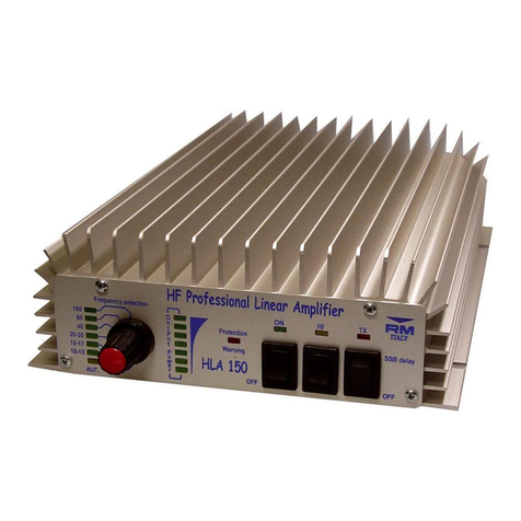
RM Italy HLA 150 User manual

RM Italy
RM Italy KL405 User manual

RM Italy
RM Italy HLA305V User manual
RM Italy
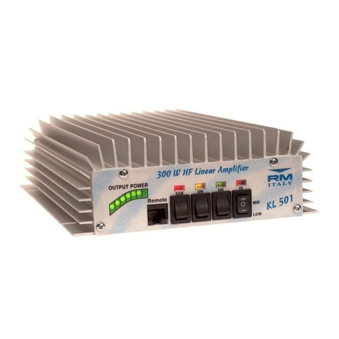
RM Italy KL 501 User manual
RM Italy
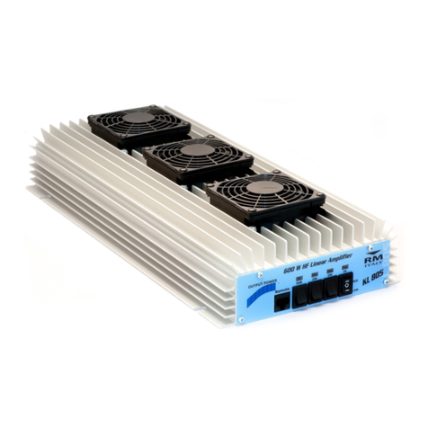
RM Italy KL805 User manual

RM Italy
RM Italy BLA 350 User manual

RM Italy
RM Italy BLA 300 User manual
RM Italy
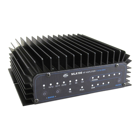
RM Italy MLA100 User manual

RM Italy
RM Italy KL503 HD User manual

RM Italy
RM Italy LA 250/V User manual

RM Italy
RM Italy BLA600 User manual
RM Italy
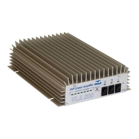
RM Italy VLA 200 User manual

RM Italy
RM Italy LA 251/V User manual

RM Italy
RM Italy KL506 User manual
RM Italy
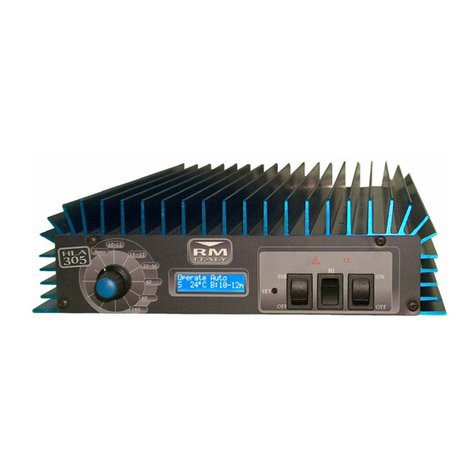
RM Italy HLA305 User manual
RM Italy
RM Italy BLA350 PLUS User manual

RM Italy
RM Italy KL703 User manual

RM Italy
RM Italy HLA305 User manual

RM Italy
RM Italy BLA600 Manual

