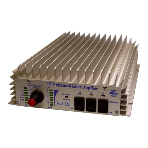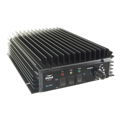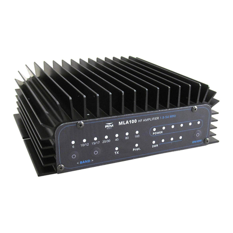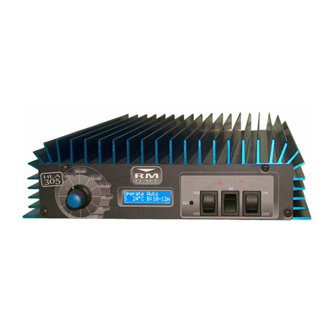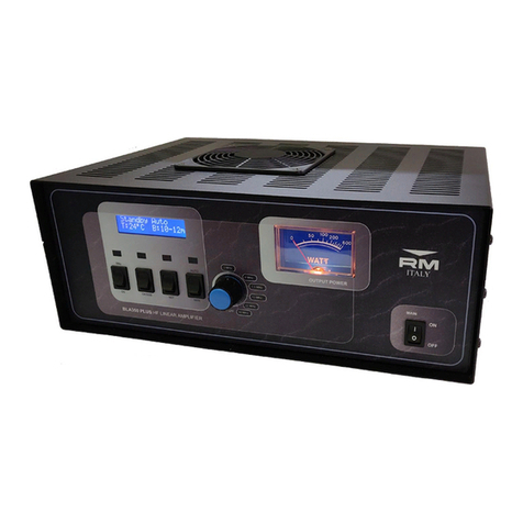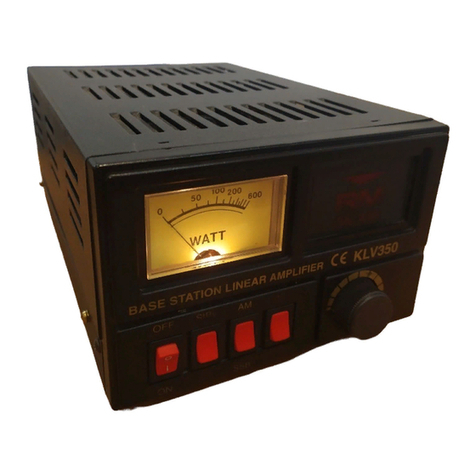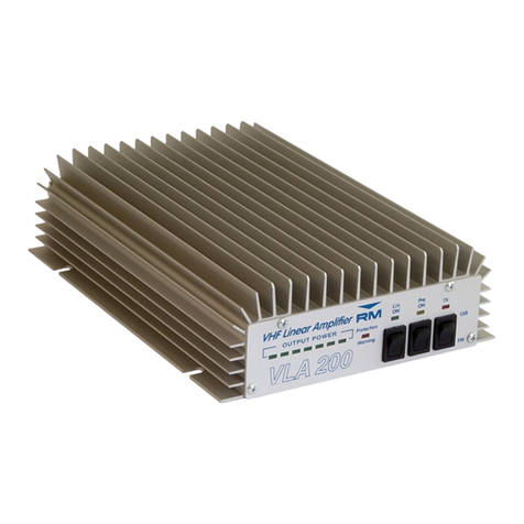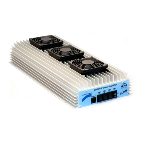
Frequenza - Frequency:............................................................... HF
Alimentazione-Supply: ............................................................. 12-14Vcc
Assorbimento - Input energy:..................................................... 10-34A
Potenza d'ingresso - Input power:............................................... 1 - 15 WAM FM
2-30W SSB CW
Potenza d'uscita - Output power: ................................................ 60-300W
AMFM
120-600 W
SSBCW
ROS ingrsso - Input SWR: .......................................................... 1.1-1.5
Funzionamento - Mode: .............................................................. AM FM SSB CW
Fusibile - Fuse: ............................................................................ 3x12A
ICommutazione elettronica.
Protezione contro l'inversione di polarità.
Preamplificatore 26 dB in ricezione, utilizzabile anche senza l'amplificatore in funzione
Connettore per comando a distanza a filo, Max 3m.
CONSIGLI D'USO
Per un corretto uso dell'amplificatore KL 501 si consiglia di posizionarlo in modo che sia
assicurato un sufficiente flusso di aria al radiatore di calore, utilizzare cavi di alimentazione il più
corti possibile e comunque non più lunghi di 3 m., possibilmente collegati direttamente alla
batteria e di sezione non inferiore a 6 mm², utilizzare un'antenna di buona qualità che accetti
almeno 600 W continui e che abbia ROS non superiore a 1.5 alla massima potenza, non rimanere
in trasmissione per lungo tempo senza intervalli ragionevoli per permettere il raffreddamento dei
transistors.In caso di utilizzo in stazione base si consiglia l'utilizzo di una batteria con
caricabatteria in tampone
Con una potenza d'ingresso superiore a 12 W AM si consiglia di non usare la posizione HI
del selettore di potenza (^).
Per l'uso del connettore remote utilizzare un cavo con connettore RJ45 di lunghezza non superiore
a 3m. Le funzioni remotabili sono le stesse presenti sul frontale del lineare.
Le funzioni dei piedini presenti sul connettore remote sono le seguenti:
1) Massa
2)Ingresso accensione preamplificatore d'antenna
3)Uscita segnale Wattmetro
4)Uscita tensione di alimentazione comando a distanza
5)Ingresso commutazione HI power
6)Ingressoaccensionelineare
7)Ingresso commutazione Low power
8)IngressoSSB
Non deve essere presente tensione sui piedini 5 e 7 contemporaneamente.
Per permettere il controllo tramite comando a distanza i comandi sulfrontale devono essere
posizionati nel seguenta modo:
Pre ON in OFF - Lin ON in OFF - SSB/AM in AM - comm. potenze in Mid
In fig.1 è presente lo schema di una possibile connesione del comando a distanza.
Il connettore PTT presente sul retro permette il controllo della commutazione direttamente
tramite il ricetrasmettitore, viene attivato cortocircuitando i due poli (o il centrale verso massa).
Usando l'ingresso PTT si consiglia di porre sempre il comando SSB/AM in AM.
ATTENZIONE !!!!L'apparato è conforme alle norme CE se usato in combinazione con il filtro 27/
586 collegato tra l'uscita a radiofrequenza dell'apparato e l'antenna.
L’uso di questo apparato è ammesso solo con veicolo fermo.
Garanzia mesi 24 dalla data dello scontrino o ricevuta.
Siricordachel'utilizzodegliamplificatorilinearièregolatodaleggispecificheequindisene
consiglia la visione prima dell'utilizzo e comunque la ditta costruttrice declina ogni responsabilità
derivata da un non corretto uso rispetto le norme vigenti.
La non osservanza delle istruzioni sopra scritte annulla ogni forma di garanzia che
comunque non include i transistors finali e le parti estetiche.
Fig 1
Pin1 Pin8
Remote
Connector
GElectronic switch.
Inversion polarity protection.
Receiving 26 dB antenna preamplifier, to be used also when the amplifier is not working.
Remote control connector
INSTRUCTION
When using Amplifier KL 501 adjust it to assure a sufficient flow of air in the aluminium dissipator.
Use supply cables as short as possible not longer than 3 meters, with a section of at least 6 mm² and
directly connected to the battery. Use a good quality Antenna, bearing at least 600 continuous Watt
and with SWR max 1.5/1. Don't transmit for long without reasonable breaks enabling transistors
cooling. When using in base station a battery with floating battery charger is advisable.
For the remote connector use, use a cable with RJ45 connector not plus length to 3m.
The remote functions are the same presents on the front of the amplifier.
The functions of the pins present on the remote connector are:
1) Ground
2) Preamplier ON input
3) Wattmeter signal output
4) Power output for remote command
5) HI power input
6) Linear ON input
7) Low power input
8) SSB input
It does not have at the same time to be present tension on pin 5 and 7.
For remote control use , the switch on linear amplifier must be put in :
Pre ON in OFF - Lin ON in OFF - SSB/AM in AM - powers comm. in Mid
In fig.1 is present an possible connection of the remote command.
On the back of amplifier is present a connector named PTT, allows the control of the
commutation through the RTX, comes activated shorting the two poles (or shortig center
to GND).
Using income PTT she advises herself to put commando SSB/AM in AM.
It is advisable not to use position HI of the power selector (^) when the input power exceeds
12 W AM
ATTENTION !!!! The item is in
compliance with CE regulations if it is
used toghether with 27/586 filter
connecting the radio frequency output of
the unit an the antenna.
The use of this device is
allowed only when the vehicle is
not in motion.
24 months warranty from date
of receipt.
Please note that the use of
linear amplifiers is ruled by specific laws,
that are to be known by the user,
anyway the manufacturer declines any
responsibility coming from an
uncorrected use.
Any warranty is cancelled if
the above instructions are not
observed. Final transistors and
estetical parts are not included in
the warranty.

