manuals.online logo
Brands
  1. Home
  2. •
  3. Brands
  4. •
  5. RM Italy
  6. •
  7. Amplifier
  8. •
  9. RM Italy BLA 300 User manual

RM Italy BLA 300 User manual

Amplificatore Lineare HF
HF Linear Amplifier
BLA 300
[[
[[
[Potenziometro regolazione sintonia preamplificatore - Preamplifier tuning
adjustment
\\
\\
\Interruttore accensione preamplificatore d' antenna - Antenna preamplifier switch
]]
]]
]Interruttore inserimento ritardo SSB - SSB delay switch
^^
^^
^Interruttore accensione lineare - Linear amplifier switch
__
__
_Interruttore inserimento attenuatore d'ingresso -Input attenuator switch
``
``
`Commutatore per la selezione del filtro passa-basso adeguato alla frequenza in uso.
Commutator to select the low-pass filter adapted to the working frequency.
aa
aa
aLed indicatore d'accensione preamplificatore - Preamplifier switching ON led
indicator
bb
bb
bLed indicatore di trasmissione - Transmission led indicator
cc
cc
cLed indicatore d'accensione lineare - Amplifier switching ON led indicator
dd
dd
dIndicatore di stato di protezione (rosso) o attenuatore d'ingresso inserito (verde) -
Protection state indicator (Red) or Input attenuator switch-ON (green)
ee
ee
eStrumento indicatore della potenza d'uscita - Output power wattmeter
ff
ff
fInterruttore generale di rete - Network switch
www.rmitaly.com
rm@rmitaly.com
]]
]]
]
\\
\\
\``
``
`
^^
^^
^
[[
[[
[
__
__
_
+
aa
aa
a
+
bb
bb
b
+
dd
dd
d
+
cc
cc
cee
ee
e
+
ff
ff
f
Mainboard
?@ABL2
Frequenza - Frequency : 1,5 - 30 MHz
: 10 - 160 meter
Alimentazione - Supply : 110 or 230/240 Vca
Assorbimento Max - Max Input energy : 3A
Potenza d'ingresso - Input power : 1 - 12 W AM - FM
: 25 W PEP
Potenza d'uscita RF - Output power : 300 W Max AM-FM
ROS ingresso - Input SWR : 1.1/1.5
Preamplificatore d'antenna sintonizzabile - Tunable antenna preamplifier : 10 - 30 MHz
ROS Massimo in antenna - Antenna SWR Max : 2.5
Funzionamento - Mode : All MODE
Fusibile - Fuse : 4 A



Descrizione
L'amplificatore lineare BLA 300 è appositamente studiato per chi ha la necessità di
elevare la potenza in antenna degli apparati decametrici a bassa potenza (tipo Yaesu FT 817,
Icom IC 703 ecc.) mantenendo elevate le caratteristiche di attenuazione delle emissioni
indesiderate (spurie ed armoniche) per effettuare collegamenti a lunga e lunghissima distanza.
Opera in tutte le bande radioamatoriali da 160 (1,8 MHz) a 10 (29,5 MHz) metri in tutti i modi
operativi.
Possiede al suo interno una serie di sei filtri passa-basso con frequenza di taglio di 3/4,5/8/15/
22/31 MHz per abbattere drasticamente le emissioni di armoniche. Il controllo della selezione
del filtro è manuale (selezione della frequenza di taglio tramite il commutatore ``
``
`) .
Un sensore termico blocca il funzionamento dell'amplificatore nel caso in cui la temperatura
diventasse eccessiva, il ripristino è automatico al rientro nel range di funzionamento normale.
Un circuito di protezione da eccessivo ROS (lo stato di protezione è visualizzato dall'accensione
con colore Rosso dell'indicatore d) provvede ad interdire il funzionamento dell'amplificatore
in caso il livello di onde stazionarie in antenna sia eccessivo , lo stesso circuito protegge lo stadio
di amplificazione dalla possibilità che un' incorretta impostazione dei filtri passa-basso lo
possano danneggiare, il ripristino avviene spegnendo per alcuni secondi l'amplificatore tramite
l'interruttore ^.
Un ulteriore circuito protegge l'amplificatore da danni per un'eccessiva potenza d'ingresso. Se
Parte posteriore - Rear wiev
gg
gg
g
+
hh
hh
h
+
ii
ii
i
+
jj
jj
j
kk
kk
k
ll
ll
l
*
*
gg
gg
gIngresso alimentazione - Network supply
hh
hh
hUscita d'antenna - Antenna output
ii
ii
iIngresso RTX - RTX Input
jj
jj
jUscita ALC - ALC output
kk
kk
kIngresso PTT - PTT Input
ll
ll
lTrimmer regolazione ALC - ALC setting
Commandboard
If the connection ALC (j)with the transmitter is used it can be necessary to adapt the
level.
For this calibration respect the following indications:
Use a wattmeter between transmitter and linear; regulate the power level of transmitter
at about 15W FM on these bands 15-17-20-30 or 40 m. Set the trimmer completely in clockwise;
switch the linear and go in transmission. Now regulate slowly the trimmer in counterclockwise
up to have about 11W in amplifier input. An excess of power could make intervene the
attenuator or the protection.
Usetheamplifieronlyforlong-distanceconnections,avoidingtoremainintransmission
for more than 5 minutes without reasonable time intervals, to permit transistors cooling.
Warranty period: 24 months from the receipt date.
The linear amplifier use is regulated from specific laws and so it is advised the vision
before the usage. The firm declines all its responsibility derived from a wrong use in compliance
with regulations.
The no observance of the previous instructions cancels any form of warranty that
anyway does not include the aesthetic parts and the final transistors.
la potenza d'ingresso supera i 12-13 W viene automaticamente inserito l'attenuatore di -3dB
(visualizzato dall'accensione del led verdedd
dd
d), se la potenza sale ancora a 25W avviene
l'esclusione dell'amplificatore indicando lo stato di protezione con l'accensione del led rosso
dd
dd
d.
Al suo interno ha installata una ventola per dissipare con maggior efficienza il calore prodotto.
La ventola funziona a velocità variabile per ridurre la rumorosità in ricezione quando il suo uso
è meno necessario.
INSTALLAZIONE
Dopo aver tolto l'amplificatore dal suo imballo ed aver controllato che non abbia subito
danni durante il trasporto, collegare, con una prolunga di RG58 lunga circa 90 cm., il
ricetrasmettitore al connettore SO239 siglato con RTX (i) e l'antenna al connettore ANT (h)
posti entrambi sul lato posteriore dell'amplificatore, assicurarsi che l'interruttore di accensione
(f) sia in posizione OFF, collegare il cavo di alimentazione fornito in dotazione alla spina
posteriore (g) assicurandosi che sia inserita completamente, l'altra estremità dovrà essere
inserita in una appropriata presa di rete.
Per il corretto funzionamento dell'amplificatore, si consiglia di utilizzare anche le connessioni
ALC (j) e PTT (k), connettendole alle corrispondenti connessioni del trasmettitore
Posizionare sempre l'amplificatore in modo da poter accedere con facilità a tutti i comandi
avendo cura di lasciare spazio intorno ad esso per permettere una buona ventilazione.
ATTENZIONE !!!
Prima dell'utilizzo dell'amplificatore verificare che antenna e alimentazione
abbianocaratteristicheadeguate.
USO
Accendere l'amplificatore tramite l'apposito interruttore (f), posizione ON, si noterà l' illumi-
narsi del wattmetro e.
Posizionare i comandi come è necessario considerando che:
Il deviatore _inserisce o disinserisce l'attenuatore d'ingresso, se l'attenuatore è inserito
si accende l'indicatore d di colore verde. L'attenuatore varia di circa 3 dB il livello di potenza
di pilotaggio dello stadio di potenza permettendo di migliorare la resa dell'amplificatore . In caso
il segnale in ingresso sia superiore ad 12 W (20 PEP) l'attenuatore si inserisce automaticamente.
L'interruttore ]se posto su SSB Delay inserisce un ritardo di circa 1- 1,5 sec. al rilascio
del relè d'antenna per luso in SSB o CW, se è utilizzato l'ingresso PTT posteriore (j), connesso
alla relativa presa sul ricetrasmettitore (modo consigliato), l'interruttore ]deve essere in
posizione OFF .
Il selettore dei filtri Passa-basso (`) deve essere posto sulla frequenza immediatamente
superiorealla frequenza di trasmissione, cioè 2MHz per 160m, 4MHz per 80m. 7,5 MHz per 40m,
15 MHz per 30 - 20m, 22 MHZ per 17 - 15m, 30 MHz per 12-10m.
Se viene selezionata una banda sbagliata quando si commuta in trasmissione si verificano due
Before using the amplifier check antenna and alimentation to have some appropriate
characteristics.
USAGE
Switch the amplifier through (f), ON position. The wattmeter (e) will light up.
Put the controls as it is necessary, considering that:
The switch _ connects or disconnects the input attenuator. If the attenuator is
connected the indicator dwill light up of green. Moreover the attenuator changes of 3 dB
the level of pilot power, permitting to improve the amplifier yield. In case of input signal is higher
than 12 W (20 PEP), attenuator is connected automatically.
If the switch ]is placed on SSB Delay, it inserts a delay of about 1-1,5 sec. at antenna
relay release for the use in SSB CW. If it is used the posterior PTT input (j) connected to the
relative plug on the two-way radio (advised way), the switch ]must be on OFF.
The low-pass filter selector (`)must be placed on the frequency just superior to the
transmission one, that is 2MHz for 160m, 4MHz for 80m. 7,5 MHz for 40m, 15 MHz for 30 - 20m,
22 MHZ for 17 - 15m, 30 MHz for 12-10m.
In case of wrong band selection when it is commutated in transmission, two situations
can happen:
1. If a filter with an excessive quench frequency is used, one or more harmonic
frequencies of transmission frequency may be emitted; however this doesn’t damage
the amplifier.
2. If the transmission frequency is greater than the quench one the amplifier protection
circuit intervenes (red led dd
dd
dignition), preventing the commutation in transmission.
The switch ^^
^^
^permits linear amplifier ignition.
The switch \\
\\
\permits antenna preamplifier ignition.
Antenna preamplifier is independent from linear amplifier working.
For a good working, with a low level of intermodulation from the strong signals
present in HF, preamplifier is made of a circuit tunable trough the control [. For the use
it is necessary to have a signal in antenna, even just audible, on the use frequency or on
a near one (preamplifier is on off). Then switch the preamplifier and tune it by the control
[,up to the point of maximum intelligibility signal.
When the amplifier is in transmission the indicator TX (b) lights up and outlet power
is indicated through the instrument (e).
Protection indicator (d) lights up (red) only if there is a danger condition for amplifier
integrity. The possible causes are:
1. selection of a filter for a frequency which is inferior to that usage one
2. excessive level of stationary waves (ROS) in antenna.
Check the filter arranged through the commutator `or ROS level in antenna before
continuing with the amplifier use.
For restoring the normal usage of the amplifier switch on and then switch off ^^
^^
^.
condizioni, se si usa un filtro con una frequenza di taglio eccessiva si rischia che venga emessa
una o più armoniche della frequenza di trasmissione, ciò comunque non danneggia l'amplifica-
tore), se la frequenza di trasmissione è maggiore di quella di taglio interviene il circuito di
protezione dell'amplificatore (accensione del LED rosso d) impedendo la commutazione in
trasmissione.
L'interruttore ^^
^^
^permette l'accensione dell'amplificatore lineare.
L'interruttore \\
\\
\permette l'accensione del preamplificatore d'antenna.
Il preamplificatore d'antenna è indipendente dal funzionamento dell'amplificatore lineare.
Per un ottimo funzionamento, con un basso livello di intermodulazione da parte dei forti segnali
presenti in HF, è costituito da un circuito accordato sintonizzabile tramite il comando [. Per l'uso
è necessario avere un segnale in antenna, anche appena udibile, sulla frequenza d'uso o su una
frequenza vicina (con preamplificatore spento), accendere il preamplificatore e sintonizzarlo con
il comando [fino al punto di massima intellegibilità del segnale.
Quando l'amplificatore è in trasmissione l'indicatore TX (b) si accende e la potenza
d'uscita viene indicata dallo strumento (e) .
L'indicatore Protection (d) si accende (rosso) solo se si è verificata una condizione di
pericolo per l'integrità dell'amplificatore. Le cause possibili sono, come già visto, la selezione
di un filtro per una frequenza inferiore a quella effettiva di utilizzo, oppure ad un eccessivo livello
di onde stazionarie (ROS) in antenna.
Controllare il filtro impostato tramite il commutatore `o il livello di ROS in antenna prima di
continuare con l'uso dell'amplificatore.
Per ripristinare l'uso normale dell'amplificatore agire su ^spegnendolo e riaccendendolo.
Se viene utilizzata la connessione ALC ( j) con il trasmettitore può essere necessario adattarne
il livello. Per questa taratura si procede come segue:
Usareun wattmetro tra trasmettitore e lineare,regolare il livello di potenza del trasmettitore a circa
15W FM su una delle seguenti bande 15-17-20-30 o 40 m, regolare il trimmer ltutto in senso
orario, accendere il lineare ed andare in trasmissione, regolare ora il trimmer llentamente in
senso antiorario fino ad avere circa 11 W in ingresso all'amplificatore, eccedere nella potenza
farebbe intervenire l'attenuatore o la protezione.
Usare l'amplificatore solo per collegamenti a lunga distanza evitando di rimanere in
trasmissione per più di 5 minuti consecutivi senza intervalli ragionevoli per permettere il
raffreddamento dei transistors.
Garanzia mesi 24 dalla data dello scontrino o ricevuta
Si ricorda che l'utilizzo degli amplificatori lineari è regolato da leggi specifiche e quindi
se ne consiglia la visione prima dell'utilizzo e comunque la ditta costruttrice declina ogni
responsabilità derivata da un non corretto uso rispetto le norme vigenti.
Lanon osservanza delleistruzionisopra scritte annullaogniforma di garanziachecomunque
non include le parti estetiche ed i transistors finali.



DESCRIPTION
The linear amplifier BLA 300 is properly studied for raising the power in antenna of
decametric apparatus at low power (such as Yaesu FT 817, Icom IC 703…) keeping high the
attenuation characteristics of unwanted emissions (extraneous and harmonic) to establish
long and very long distance connections.
It operates in all the radio amateur bands from 160 (1,8 MHz) to 10 (29,5 MHz) metres
and in all the operative ways.
It internally has a set of six low-pass filters with cut-off frequency of 3/4, 5/8/15/22/
31 MHz for definitively eliminating harmonic emissions. The filter selection control is manual
(cut-off frequency through commutator `).
A thermic sensor stops the amplifier working in case of increased temperature. The
reset is automatic in the normal working range.
A protection circuit for an excess of ROS ( protection state is displayed through the
red colour of the indicator d) provides to stop the amplifier if the stationary waves level in
antenna is too high.
The same circuit protects the stage of amplification for a possible wrong statement
of the low-pass filters. Reset is by switching off the amplifier through the switch ^for few
seconds.
A further circuit protects the amplifier from the damages for an excess of input power.
If this one overcomes the 12-13 W the attenuator is automatically set in at -3Db (displayed by
green led d ignition ). If the power goes up to 25 W the amplifier is excluded and the state
of protection is indicated through the red led (d) ignition.
Internally it has a fan to dissipate the produced heat. It runs variable-speed to reduce
the noise in reception when his usage is less necessary.
INSTALLATION
After taking away the amplifier from its packing and checking any possible damages
during the transport, connect, with a 90 cm long RG58 patch cord, the two-way radio to SO239
connector, named RTX (i)and the antenna to ANT (h) connector, both placed on the back
of the amplifier.
Make sure the network switch (f) is on off and connect the supply cable on issue
to the back plug (g), cutting it in completely. The other extremity has to be plugged in an
appropriate net drive.
For the correct working of the amplifier, it is advised to use also the connections ALC
(j) and PTT (k), linking them to the correspondent amplifier connections.
Always put the amplifier so as to reach easily all the controls, leaving some space
around it to permit a good ventilation.
ATTENTION

Other RM Italy Amplifier manuals

RM Italy BLA 350 User manual

RM Italy

RM Italy BLA 350 User manual

RM Italy KL703 User manual

RM Italy

RM Italy KL703 User manual

RM Italy KLV 1000 P User manual

RM Italy

RM Italy KLV 1000 P User manual

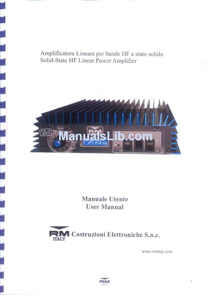
RM Italy HLA305 User manual

RM Italy

RM Italy HLA305 User manual

RM Italy LA 250/V User manual

RM Italy

RM Italy LA 250/V User manual

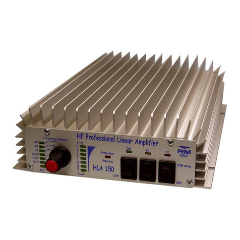
RM Italy HLA 150 User manual

RM Italy

RM Italy HLA 150 User manual

RM Italy HLA305 User manual

RM Italy

RM Italy HLA305 User manual

RM Italy BLA600 User manual

RM Italy

RM Italy BLA600 User manual

RM Italy BLA600 Manual

RM Italy

RM Italy BLA600 Manual

RM Italy LA 251/V User manual

RM Italy

RM Italy LA 251/V User manual

RM Italy KL405 User manual

RM Italy

RM Italy KL405 User manual

RM Italy HLA305V User manual

RM Italy

RM Italy HLA305V User manual

RM Italy KL506 User manual

RM Italy

RM Italy KL506 User manual

RM Italy BLA350 PLUS User manual

RM Italy

RM Italy BLA350 PLUS User manual

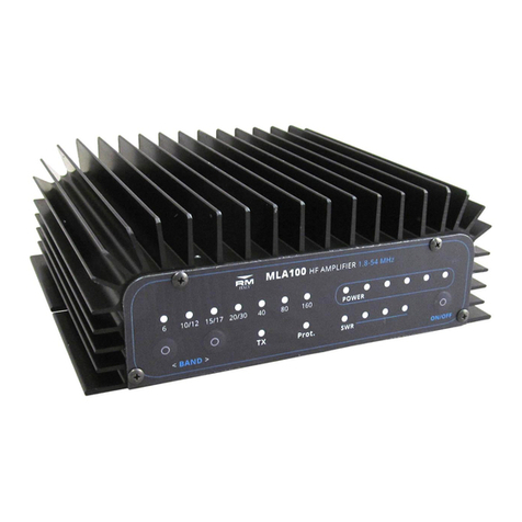
RM Italy MLA100 User manual

RM Italy

RM Italy MLA100 User manual

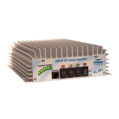
RM Italy KL 501 User manual

RM Italy

RM Italy KL 501 User manual

RM Italy KLV 350 User manual

RM Italy

RM Italy KLV 350 User manual

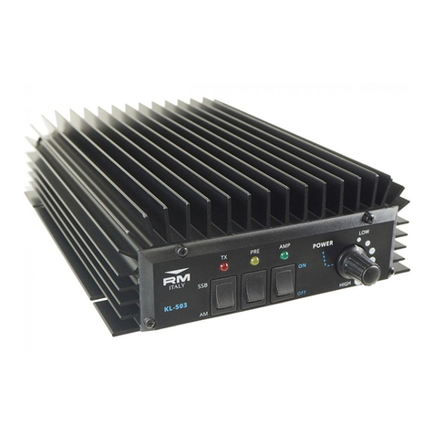
RM Italy KL503 User manual

RM Italy

RM Italy KL503 User manual

RM Italy KL505 User manual

RM Italy

RM Italy KL505 User manual

RM Italy KL503 HD User manual

RM Italy

RM Italy KL503 HD User manual

RM Italy HLA 300 User manual

RM Italy

RM Italy HLA 300 User manual

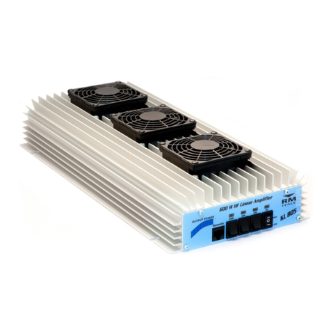
RM Italy KL805 User manual

RM Italy

RM Italy KL805 User manual

RM Italy VLA 200 User manual

RM Italy

RM Italy VLA 200 User manual

Popular Amplifier manuals by other brands

Ecler eGPA SERIES user manual

Ecler

Ecler eGPA SERIES user manual

Philex 27823BMG user guide

Philex

Philex 27823BMG user guide

Kenwood W-38 Installation and operating manual

Kenwood

Kenwood W-38 Installation and operating manual

Fracarro AMP9564 operating instructions

Fracarro

Fracarro AMP9564 operating instructions

Audiovox Phase Linear UPA224 owner's manual

Audiovox

Audiovox Phase Linear UPA224 owner's manual

Kenwood KAC-6404 Service manual

Kenwood

Kenwood KAC-6404 Service manual

Suhr SL-68 user manual

Suhr

Suhr SL-68 user manual

Pico Macom L860 Specifications

Pico Macom

Pico Macom L860 Specifications

Jetter JM-206-230 user manual

Jetter

Jetter JM-206-230 user manual

Margules U-280 SC 30TH ANNIVERSARY owner's manual

Margules

Margules U-280 SC 30TH ANNIVERSARY owner's manual

The Fisher TX55 Service manual

The Fisher

The Fisher TX55 Service manual

DAPAudio VPA-060 Product guide

DAPAudio

DAPAudio VPA-060 Product guide

FAME AG-10AM user manual

FAME

FAME AG-10AM user manual

Coda ?5 user manual

Coda

Coda ?5 user manual

Trinnov Audio Altitude32 user manual

Trinnov Audio

Trinnov Audio Altitude32 user manual

Polk Audio PA D5000.5 owner's manual

Polk Audio

Polk Audio PA D5000.5 owner's manual

DaytonAudio Class-T instructions

DaytonAudio

DaytonAudio Class-T instructions

Crystal Vision Indigo VDA210M HD user manual

Crystal Vision

Crystal Vision Indigo VDA210M HD user manual

manuals.online logo
manuals.online logoBrands
  • About & Mission
  • Contact us
  • Privacy Policy
  • Terms and Conditions

Copyright 2025 Manuals.Online. All Rights Reserved.