RMG SailWinch SmartWinch 280D User manual

RMG SAILWINCH
SmartWinch
U S E R G U I D E

Contents
1.Introduction .................................................. 1
2.SummaryofFeatures........................................... 1
3. Special SmartWinch Features .................................... 1
4.Batteries..................................................... 3
5.Wiring ...................................................... 4
6.StandardConnections .......................................... 5
7.AlternateConnections .......................................... 5
8.Mounting.................................................... 6
9.Sheeting..................................................... 7
10.SettingUp................................................... 8
11. Setting TX End Points, Travel and Battery Monitoring . . . . . . . . . . . . . . . . 9
12. Adjusting Deceleration, Scaled Linear Travel, Speed & Dead Band . . . . . 10
13.Maintenance ................................................ 12
14.Warranty................................................... 12
15.MechanicalSpecifications ..................................... 13
16.ElectricalSpecifications ....................................... 13
The SmartWinch is manufactured by
RMG SAILWINCH
66 Radford Rd
Angaston 5353
South Australia
Phone: 61 (0)8 8564 2444
Fax: 61 (0)8 8564 3474
E-mail: [email protected]
Internet: www.rmgsw.com
0307

SmartWinch User Guide page 1
1. Introduction
Thank-you for purchasing a SmartWinch. We hope you have many
years of trouble free and successful sailing using our product. If there are any
problems to be solved or queries to be answered please do not hesitate to call.
Please take the time to read this booklet through. There are a few do's and don'ts,
some very important points and some helpful hints.
2. Summary of Features
•3.8 to 9 volt operating range
COptional battery monitoring and low battery shutdown
CIntegral 5 volt regulator for single battery operation
CTravel adjustable from 1 to 6 revolutions depending on model
CAutomatic shutdown when stalled
CDynamic Pulse Width Modulation drive
CProgrammable forTX end point limits for overrun protection
CAdjustable deceleration rate
CAdjustable Speed
CAdjustable Scaled Linear Travel.
CAdjustable Input Dead Bnad
CBall bearing output.
3. Special SmartWinch Features
Dynamic Pulse Width Modulation
Servo systems use Pulse Width Modulation to reduce power and speed
as the desired position is approached. This gives finer and smoother control when
small movements are required. But the problem with standard P.W.M. is that as
the desired position is approached, the reduction in power can cause the servo to
stop short. This can result in excess power consumption, overheating and
damage. This is what's happening when a servo is not moving but is buzzing.
However, unlike other winches and servos the SmartWinch has dynamic P.W.M.
If the SmartWinch controller detects that it has not reached the desired position,
it will increase power up to 100% if necessary until it does. If once 100% power
is reached and the SmartWinch is still not able to reach its desired position then
the stall protection feature can be activated.

SmartWinch User Guide page 2
Stall Protection
When a conventional winch becomes stalled, it will stay stalled until the problem
is solved or the battery is flattened or the electronics damaged etc. But the
SmartWinch knows when it is stalled and can protect itself by shutting down.
The winch then signals that it is stalled by sounding a two-tone beep at 2 second
intervals until reset. To reset the winch simply move the tx stick in the opposite
direction or turn the TX or winch off and on again.
Battery Monitoring
If desired, the winch can monitor NiCad or NimH packs of 5 or 6 cells or 6 volt
sealed lead acid gel cells. If the voltage is below the warning level a warning
signal (5 rising tones) will sound when the winch is switched on. If, during
normal operation the voltage falls below the shutdown level, the winch will drive
to half way and hold there until the battery is replaced or voltage recovers.
Adjustable Deceleration Rate
The time taken to decelerate from full speed to stopped can be adjusted. At
minimum, deceleration takes around 1 second. Maximum is around 0.1 seconds.
Depending on supply voltage used, the SmartWinch may over shoot and hunt so
experimentation is advised. The default setting is 70% of maximum.
Scaled Linear Travel Response
Travel response to the first 25% of TX stick movement out from close hauled is
adjustable from 1:1 at minimum to a maximum of 4:1. The default setting is 1:1.
For example, if 50% is selected, each increment of the first 25% of the stick
range results in half the travel of the default setting. This feature is similar to
exponential travel adjustment in some transmitters. However scaled linear has the
advantage of consistent incremental travel over the first 25% of stick movement
whereas exponential is constantly varying.
Variable Speed
This feature is included for some non sailwinch applications where a certain
speed is important. Also some skippers may prefer a slower sailwinch response
to suit their particular sailing style. The default setting is maximum speed.
Input Dead band
Input dead band is the amount dithering in the RX signal that a servo can
tolerate without responding to by constantly jittering. This is now adjustable from
2 to 15 microseconds. Dead Band adjustment allows the optimisation of TX fine
trim control. The default setting is 10 microseconds.

SmartWinch User Guide page 3
Table 1
Level Detect Warn Shutdown
1. 6V gel cell < 6.5 < 5.1 < 5.0
2. 5 cells > 6.5 < 5.5 < 5.0
3. 6 cells > 7.5 < 6.6 < 6.0
Battery Monitoring Voltages
4. Batteries
Voltage Range
Supply voltage range is from 3.8V to 9V. Should a voltage outside that range be
applied the winch will not operate. No damage can be done unless reverse
polarity or > 12 volts is used. While the winch will operate down to 3.8 volts, the
minimum should be a 4 pack of NiCad or NimH. This will give room for voltage
drop as the battery pack discharges.
Pack Size
The recommended battery pack is 5 or 6 NiCad or NimH cells or a 2 cell LiPo.
Alternatively a 6V sealed lead acid gel battery may be used. These days with
higher cell energy densities, AA size NiCad or NimH cells can have capacities of
up to about 2500 mAh. With these high capacities it is also feasible to use AAA
size cells with a significant weight saving.
Snap In Battery Holders
Snap in battery holders are not recommended. Their weak electrical connections
can result in severe voltage drop which may cause erratic winch behaviour.
Compounding this problem is that in most cases these packs only have servo size
wiring which can not supply the current required by the winch. 4, 5 or 6 cell
packs should be fully soldered.
Battery Life
Battery life depends on many variables. But as a rough guide, provided you have
a good low friction sheeting system, you could expect to get about 12 to 16 races
of about 10 to 15 minutes duration in conditions of around 8 to 10 knots from a 5
pack of 1000mAh AA's.

SmartWinch User Guide page 4
Fig. 1 Servo Connector
5. Wiring
Regulator
The SmartWinch contains a 5 volt regulator which can supply up to 1 amp of
current to the controller circuit, radio receiver (rx) and rudder servo. This allows
for the use of only one battery pack inside the yacht. The motor runs on the full
battery voltage via the MOSFET output circuit.
Supply Leads
Wiring and connectors from winch supply leads to battery pack must be at least
0.5mm cross section and rated at least 3 Amps. Switches used should be rated at
2
least 3 Amps also. Standard servo size wiring is not adequate. It will cause
severe voltage drop between battery and winch and should not be used. All joints
should be soldered and then coated with Vaseline petroleum jelly to protect from
corrosion (black wire). Use Vaseline on servo connectors also.
Supply Polarity
Power supply / battery lead connectors must be polarised so that it is impossible
to accidentally reverse the supply polarity. The control circuit and radio gear is
protected by the voltage regulator and will not be damaged by reverse polarity
but the output circuit could be seriously
damaged.
Servo Connector (RX Lead)
The connector supplied is compatible with JR,
Futaba, Hitec etc. Take care when inserting
connector into receivers other than JR or Hitec.
Make sure that polarity is correct. In the case of
Sanwa receivers, check the polarity of the Sanwa
servo leads first as early Sanwa receivers require
the centre lead to be negative. (see figure 1)
SmartWinch User Guide page 5
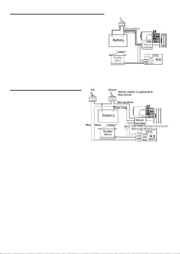
Fig. 3 Standard Connections
Fig. 4 Alternate Connections
6. Standard Connections
In most cases the best circuit for winch, radio
and battery is also the simplest as shown in
figure 3.
In this system there must be no receiver
battery connection. Power for receiver is
supplied by internal 5 volt regulator.
7. Alternate Connections
If more than just winch and a rudder
servo is used it is advisable to
bypass the winch's internal voltage
regulator and connect the battery
direct to the rx. See Figure 4. This
is because the winch regulator and
or servo lead may not be able to
supply the current needed by extra
servos causing a voltage drop.
Servo connector lead red wire must be disconnected when RX battery socket in
use. Remove the red wire socket from the connector and tape it back to the lead.
Winch switch can be omitted in this case as the winch will not operate when rx is
turned off. RX must be able to take full battery voltage.

SmartWinch User Guide page 6
Fig. 5 Mounting Dims.
Fig. 6 Mount Bracket
8. Mounting
Deck Mounting
The recommended method of mounting the winch is to fix it to the underside of
the deck with output shaft passing through the deck. Maximum deck thickness
3mm.
Sealing
Prior to fixing the winch to the underside of the deck, the mounting face, spigot
and "V" ring seal on the shaft immediately below the hexagonal section of the
output shaft should be given a liberal coating of Vaseline petroleum jelly or
Silicone grease to form a seal. Coat the two M3 mounting screws as well. Before
fitting the drum give the area around the 'V' ring seal an extra coat of Vaseline.
Below Deck Mount
For below deck mounting it is usually best to mount the winch with shaft
horizontally. You may wish to make a bracket such as the one at left to assist in
below deck installation.

SmartWinch User Guide page 7
9. Sheeting
Drum Size vs Performance
Unless specified otherwise when ordering, the 280D and 280DL are supplied
with a 26mm drum. The 380D and 380HD are supplied with a 32mm drum. If
faster or slower performance is desired an extra drum may be purchased. Write or
phone for pricing. Our web site has details of several other drum options.
The size of drum affects the way the winch performs. Smaller diameter means
more revolutions are required therefore sheet speed is slower. However with
smaller diameter a higher sheeting force is achieved. And vice versa if larger
diameter is used. Similar changes in sheeting performance can be achieved by
changing the supply voltage.
Sheeting Systems
There are many ways to approach the sheeting on an R/C yacht and no one
method can be considered to be "the best way". The two main categories of
sheeting systems used on drum type winches are described below. Either system
can be used above or below deck.
#Single sheet - tension line.This is where only one side of the
drum is used and light tension is applied by an elastic tension line
which is attached to the deck. It's purpose is to prevent the loss of
wraps around the drum during sheeting out.
#Double sheet - return line. Where instead of an elastic tension
line a return line is attached the top side of the drum. As the winch
sheets out the return line is winding in maintaining tension on the load
sheet. As the winch is sheeted in the return line will wind out.
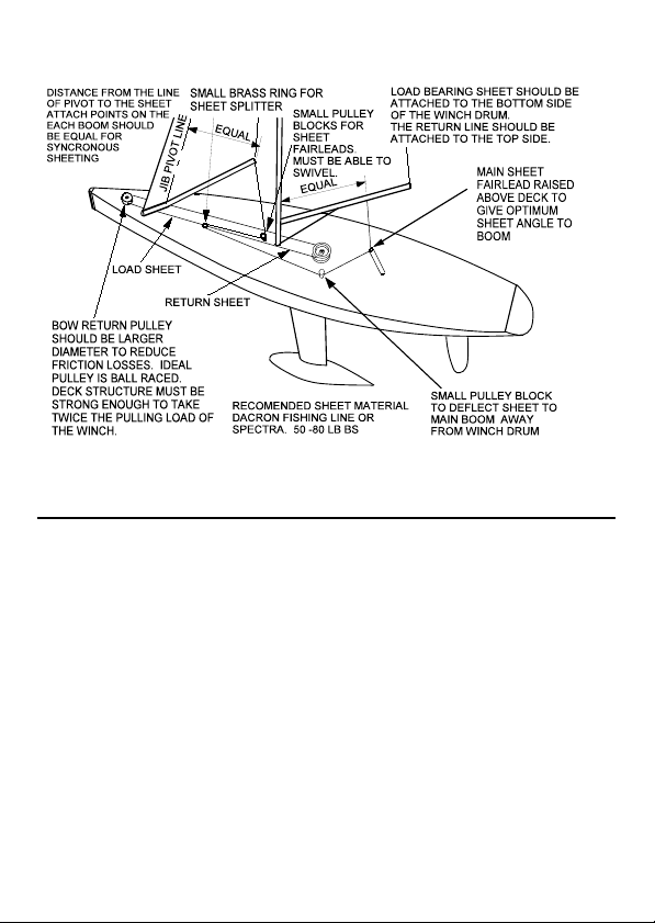
Figure 7 shows a typical arrangement for a double sheet above deck system. To
make this a single sheet tension line system, simply replace the return line with
an elastic tension line. Attach it to the sheet splitter and a fixed point near the
stern to give as much length to the elastic material as possible.
SmartWinch User Guide page 8
Fig. 7 Sheeting
10. Setting Up
It is not essential to perform the setup procedure to use the winch. Each winch
has “factory default” settings. However, setting TX end points and Travel is
recommended to give the overrun protection.
Setup can be performed as many times as desired. Each time setup is performed,
the previous settings are overwritten.
Normal Operation
To use the winch, the TX must be switched on before the SmartWinch. If the TX
is switched on after the SmartWinch, the SmartWinch will not operate other than
to allow entry to setup mode. Setup mode is not entered unless a long beep is
heard. The earliest this can happen is 10 seconds after turning the winch on. If
setup mode is accidentally entered, just turn the SmartWinch off then restart with
the TX on.

SmartWinch User Guide page 9
11. Setting TX End Points, Travel and Battery Monitoring
These settings must be done in sequence. For example, to make an adjustment to
travel, the TX end points must be set at the same time.
1 Start with; Winch off, TX on, RX lead plug out of RX, TX stick
at close hauled and trim set to minimum.
When the winch is switched on with the plug out ouf RX, it will countdown by
sounding a single beep once per second for the first 9 seconds.
2. Turn winch on and wait 10 seconds till the 3 quick beep
signal then push plug into the RX within 2 seconds.
If a single long beep is heard, setup mode has been entered and the TX end point
for close hauled position has been sampled. If not then restart the procedure..
3. Pull plug out of RX.
4. Move TX stick (not trimmer) to opposite end for sails full out
then push plug into RX.
A long beep will indicate that the TX end point for sails full out position has
been sampled.
5. Pull plug out of RX
A 3 beep signal indicates that the TX end points have been stored. The winch
can be turned off now if travel or battery setting changes not needed. Otherwise
continue on to step 6.
6. Detach the sheet lines or remove the drum.
When the plug is next inserted, the winch will drive itself to the travel starting
point. The winch must be free to drive to this position. If not sure then remove
the drum or disconnect the sheets.
7. Move TX stick back to close hauled then push plug in RX.
Once travel starting point is reached, it will sound 2 beeps. You can now drive
the winch using the TX. Install the drum and setup the sheets so that the main
boom is at close hauled when TX stick is at close hauled. Take care when
driving the winch with sheets attached as it is set for maximum travel at this time
and it would be easy to overrun. The winch will drive at 1/3rd normal speed
during this travel setting phase of setup.

SmartWinch User Guide page 10
8. Drive winch out (using TX stick) till the main boom is at the
desired fully sheeted out position. With the winch in this
position, pause for at least one second without moving the
winch, then remove RX plug.
Three beeps indicates that the new travel setting is stored. If you do not wish to
make any changes to your battery monitoring settings, switch winch off now and
setup is complete.
Or if you wish to change the existing battery monitoring settings then perform
either step 9a or 9b.
9a To enable battery monitoring, push plug into RX and wait till you
hear either 1, 2 or 3 quick beeps. Battery must be fully
charged for correct detection of number of cells.
9b To disable battery monitoring, push plug into RX and
immediately pull it out again (within about 1 second).
If three rising tones have sounded, 9b was performed and battery monitoring is
now off. If 1, 2 or 3 quick beeps were heard then step 9a was performed and
battery monitoring is turned on. The number of beeps corresponds to the battery
monitoring level set. See table 1.
Once setup is complete, the winch must be switched off.
12. Adjusting Dec Rate, Scaled Linear Travel, Speed & Dead Band
For a description of these features, see page 2. Each of these settings has a
separate entry point and can be adjusted independently. For optimum setting of
these features it is important to already have the SmartWinch set for TX end
points. However setting end points does not need to be done each time one of
these adjustments is made.
For each setting, start with; SmartWinch turned off, TX turned on, TX trim set to
minimum, RX lead plug out of RX and TX stick in desired position. For each
adjustment, select close hauled for minimum, full out for maximum or an
intermediate position as desired. Note that the SmartWinch will not drive while
making these adjustments. There is no need to remove drum or sheets.

SmartWinch User Guide page 11
Deceleration Rate Adjustment
1 Turn Winch on and wait 14 seconds till the 3 rising tones
signal then push plug into RX within 2 seconds.
If a single long beep is heard, the adjustment has been noted. If not then the
plug was not inserted in time so turn winch off and start again.
2 Pull plug out of RX.
A 3 quick beeps signal will indicate the new setting has been saved. Turn winch
off.
Scaled Linear Travel Adjustment
1 Turn Winch on and wait 17 seconds till the 2 quick beeps
signal then push plug into RX within 2 seconds.
If a single long beep is heard, the adjustment has been noted. If not then the
plug was not inserted in time so turn winch off and start again.
2 Pull plug out of RX
A 3 quick beeps signal will indicate the new setting has been saved. Turn winch
off.
Speed Adjustment
1 Turn Winch on and wait 20 seconds till the 3 quick beeps
signal then push plug into RX within 2 seconds.
If a single long beep is heard, the adjustment has been noted. If not then the
plug was not inserted in time so turn winch off and start again.
2 Pull plug out of RX
A 3 quick beeps signal will indicate the new setting has been saved. Turn winch
off.
Input Signal Dead Band Adjustment
1 Turn Winch on and wait 23 seconds till the 4 quick beeps
signal then push plug into RX within 2 seconds.
If a single long beep is heard, the adjustment has been noted. If not then the
plug was not inserted in time so turn winch off and start again.
2 Pull plug out of RX.
A 3 quick beeps signal will indicate the new setting has been saved. Turn winch
off.

SmartWinch User Guide page 12
13. Maintenance
• Spray the winch motor only with water repellant lubricating sprays.
Apply the spray directly into the motor. Avoid getting spray on
electrical wires or feedback potentiometer and controller enclosure
grommet. Note: These sprays contain flammable propellants and
solvents. Allow a few minutes for the flammable components to
evaporate before running the winch.
• Maintain a coating of white petroleum jelly (Vaseline) or Silicone
grease on all electrical connectors inside the yacht to protect against
'black wire' corrosion.
• Regularly re-pack the white petroleum jelly or Silicone grease under
the drum of deck mounted winches to protect the ball bearing.
Regularly remove the drum and re-coat the area around the shaft.
• Drain the boat of water as often as is required to keep the level of
water in the boat to an absolute minimum. After each days sailing
drain boat and leave hatch off to allow the boat to breathe and dry out.
This is important for all of the boat’s electrics.
• Do not attempt to seal the motor in any way. It must be able to breathe
for cooling purposes and also to dry out should moisture get in.
• Try to keep gears clean. Greasing is not necessary. Grease will only
attract grit which can damage the gears and will make the winch very
noisy.
14. Warranty
Your new SmartWinch is covered by a 12 month warranty. Should
any faults be found and are considered by RMG SailWinch to be our fault, we
will repair and return the winch to you free of charge.

SmartWinch User Guide page 13
15. Mechanical Specifications Table 2
Specification 280D (DL) 380D (HD) Unit
Max Power 10.7 14.3 W atts
No Load Speed 4.4(3.1) 3.5 revs/sec
No Load Speed 359 (286) 312 mm/sec
Stall Torque 15.9 (19.9) 29.9 kg.cm
Standard Drum 26 32 mm
Maximum Turns 4.8 (6) 6 (9.6) revs
Travel Range 70-405 (85-490) 80-610 (130 - 975) mm
Dimensions 74x54x59 79x54x60 mm
W eight 134 168 (175) gm
16. Electrical Specifications Table 3
Specification 280D (DL) 380D (HD) Unit
Idle (Stationary) Current 23 23 mAmps
No Load Running Current 550 650 mAmps
Stall Current 12 18 Amps
Maxim um Supply voltage 9 9 Volts
Minimum Supply voltage 3.8 3.8 Volts
Performance specifications based on a constant voltage supply of 6V and
standard drum size. Performance specifications may vary depending on supply
battery voltage and capacity and drum size etc.
This manual suits for next models
3
Table of contents
Popular Marine Equipment manuals by other brands


ESP
ESP MAGDUO MAGDUOSRSQ Installation and maintenance instructions

Allen-Bradley
Allen-Bradley PowerFlex 755T installation instructions

Venitem
Venitem ONDA Technical manual

Nexus 21
Nexus 21 Autopilot Installation and operation manual

Teledyne
Teledyne RIVERRAY Deployment guide

Teledyne
Teledyne PINNACLE 45 Deployment guide