manuals.online logo
Brands
  1. Home
  2. •
  3. Brands
  4. •
  5. E2S
  6. •
  7. Marine Equipment
  8. •
  9. E2S IS-pA1 User manual

E2S IS-pA1 User manual

Other E2S Marine Equipment manuals

E2S GNExS2F User manual

E2S

E2S GNExS2F User manual

E2S E2xS121EG Troubleshooting guide

E2S

E2S E2xS121EG Troubleshooting guide

E2S BExA120D User manual

E2S

E2S BExA120D User manual

E2S STExB2LD2 User manual

E2S

E2S STExB2LD2 User manual

E2S A100 AlertAlarm User manual

E2S

E2S A100 AlertAlarm User manual

E2S E2xS1R User manual

E2S

E2S E2xS1R User manual

E2S A105N User manual

E2S

E2S A105N User manual

E2S GNExS2 User manual

E2S

E2S GNExS2 User manual

E2S D1xS2FDC024-A User manual

E2S

E2S D1xS2FDC024-A User manual

E2S BExDCTS110-05D User manual

E2S

E2S BExDCTS110-05D User manual

E2S DL112H User manual

E2S

E2S DL112H User manual

E2S BE S120D Series User manual

E2S

E2S BE S120D Series User manual

E2S A105NSONTEL User manual

E2S

E2S A105NSONTEL User manual

E2S D1xS1RDC024-D User manual

E2S

E2S D1xS1RDC024-D User manual

E2S BExCS110-05D User manual

E2S

E2S BExCS110-05D User manual

E2S AlertAlight AL105N Series User manual

E2S

E2S AlertAlight AL105N Series User manual

E2S STExS1 User manual

E2S

E2S STExS1 User manual

E2S BExCS110-L2D-P Series User manual

E2S

E2S BExCS110-L2D-P Series User manual

E2S E2 S2R Series User manual

E2S

E2S E2 S2R Series User manual

E2S AlertAlarm A105N User manual

E2S

E2S AlertAlarm A105N User manual

E2S AlertAlight AL112NXDC012 User manual

E2S

E2S AlertAlight AL112NXDC012 User manual

E2S Minialert IS-mC1 User manual

E2S

E2S Minialert IS-mC1 User manual

E2S D1xS1 Series User manual

E2S

E2S D1xS1 Series User manual

E2S E2xS1RDC024 Manual

E2S

E2S E2xS1RDC024 Manual

Popular Marine Equipment manuals by other brands

POWERWINCH 825 Operation manual

POWERWINCH

POWERWINCH 825 Operation manual

JRC JLN-628 brochure

JRC

JRC JLN-628 brochure

DIGITAL YACHT PilotLink2 Product handbook

DIGITAL YACHT

DIGITAL YACHT PilotLink2 Product handbook

Clarion CMS2 Owner's manual & installation manual

Clarion

Clarion CMS2 Owner's manual & installation manual

EBS M7000 installation manual

EBS

EBS M7000 installation manual

Kongsberg M3 Bathy installation manual

Kongsberg

Kongsberg M3 Bathy installation manual

NPK SCS-1002 operating manual

NPK

NPK SCS-1002 operating manual

Furuno FE-800 installation manual

Furuno

Furuno FE-800 installation manual

Harken 1561 instructions

Harken

Harken 1561 instructions

Simrad DD15 manual

Simrad

Simrad DD15 manual

Notifier FS-BSO Installation and maintenance instructions

Notifier

Notifier FS-BSO Installation and maintenance instructions

Raymarine ST40 Quick reference guide

Raymarine

Raymarine ST40 Quick reference guide

Raymarine Maxiview ST80 Owner's handbook

Raymarine

Raymarine Maxiview ST80 Owner's handbook

GUIDANCE MARINE 20- Series Installer's guide

GUIDANCE MARINE

GUIDANCE MARINE 20- Series Installer's guide

R2Sonic 2026 Operation manual

R2Sonic

R2Sonic 2026 Operation manual

COBHAM SAILOR 6000 installation manual

COBHAM

COBHAM SAILOR 6000 installation manual

Raymarine ST60 Tridata Owner's handbook

Raymarine

Raymarine ST60 Tridata Owner's handbook

Furuno Navtex NX-700-A Operator's manual

Furuno

Furuno Navtex NX-700-A Operator's manual

manuals.online logo
manuals.online logoBrands
  • About & Mission
  • Contact us
  • Privacy Policy
  • Terms and Conditions

Copyright 2025 Manuals.Online. All Rights Reserved.

_______________________________________________________________________________________________________________________________
European Safety Systems Ltd. Impress House, Mansell Road, Acton, London W3 7QH sales@e2s.com Tel: +44 (0)20 8743 8880
www.e2s.com Fax: +44 (0)20 8740 4200
Document No. D160-00-001-IS Issue C08-01-20 Sheet 1 of 2
INSTRUCTION MANUAL
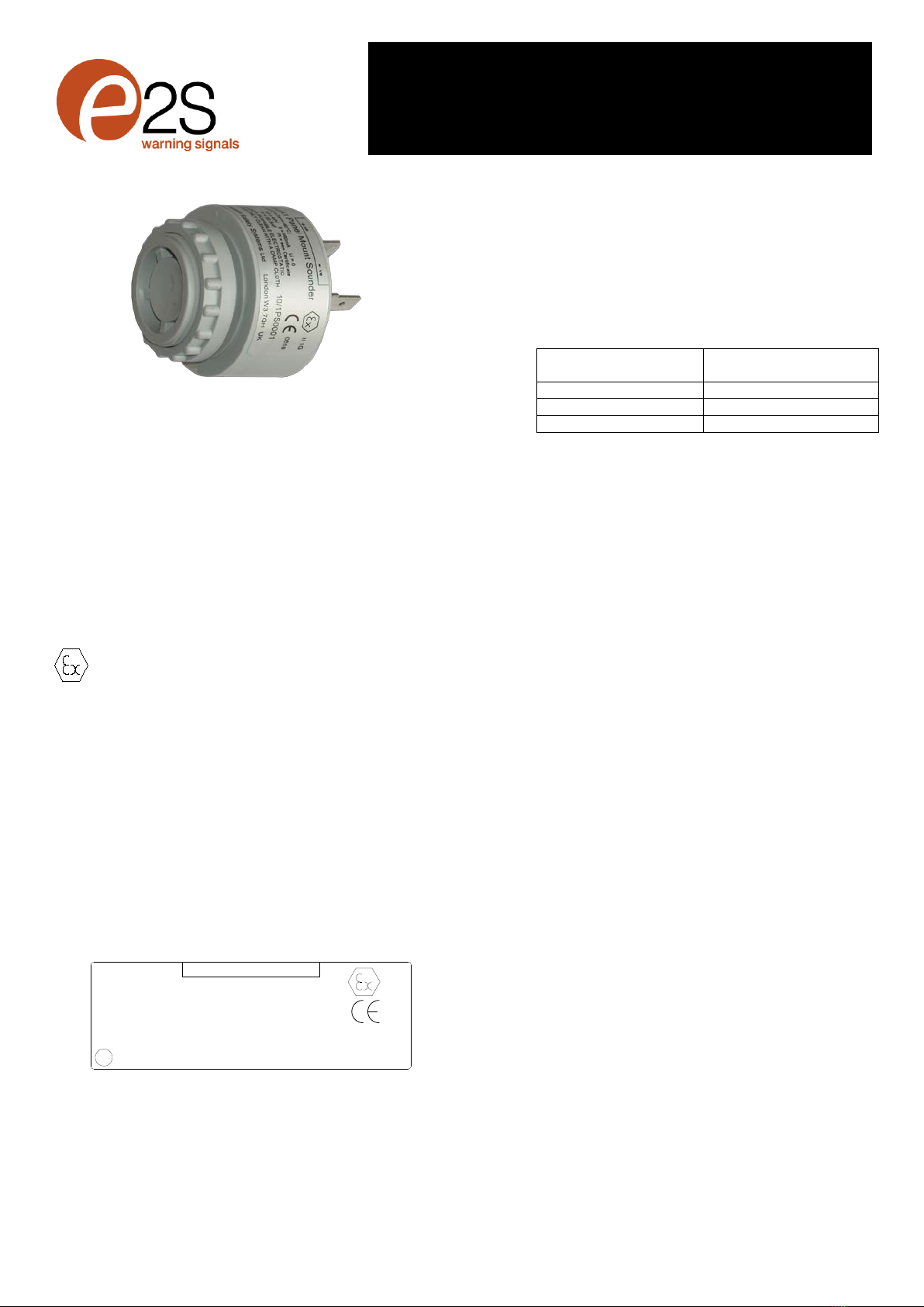
IS-pA1 Intrinsically Safe
ATEX and IECEx Panel Mount Sounder
1) Introduction
The IS-pA1 is an ATEX and IECEx certified intrinsically safe
Panel Mount Sounder which can produce a loud warning
signal in a hazardous area. The sounder has been designed
to operate in gas groups IIA and IIB via ATEX and IECEx
certified Zener Barriers or Galvanic Isolators. The sounder
may be tested or used in safe areas without using a Zener
Barrier or Galvanic Isolator,
2) Intrinsic Safety Certification
2.1 ATEX and IECEx certificates
SIRA 10ATEX2137 IECEx SIR 10.0073
The IS-pA1 sounder complies with the following standards:-
EN IEC 60079-0:2018 IEC60079-0:2017 (Ed7)
EN60079-11:2012 IEC60079-11:2011 (Ed6)
IEC60079-26:2014-10 (Ed3)
The sounder carries the Community Mark and subject to local
codes of practice, may be installed in any of the EEA member
countries. This instruction sheet describes installations which
conform to standard EN60079:14:2008 Electrical Installation
in Hazardous Areas. When designing systems for installation
outside the UK, the local Code of Practice should be
consulted.
1 The certification marking is as follows:
II 1G
2813
SIRA10ATEX2137
IECEx SIR 10.0073 Ui = 40V Ii = 660mA Li = 0
Ex ia IIB T4/5/6 Ga (-40ºC <=Ta<= +60°C)
Ci = 32.5nF Pi Determines T-Class, see certificate
WARNING:
TOAVOIDA POSSIBLE ELECTROSTATIC
CHARGE ONLY CLEAN WITHA DAMP CLOTH
+ve -ve
IS-pA1 Panel Mount Sounder
european safety systems ltd. London W3 7QH UK
10/1PS0001
e2S
The equipment may be used in Zones 0, 1 and 2
with flammable gases and vapours
with Apparatus Groups IIA and IIB
Temperature Classes T1, T2, T3, T4, T5 and T6.
The equipment has the following safety
parameters:-
Ui = 40V Ii = 660mA Pi = See below
Li = 0 Ci = 32.5nF
With respect to Temperature Class the following
limitations on maximum input power Piare
applicable:
Temperature Class
Maximum input Power
Pi
T1, T2, T3, T4
1.3W
T5
0.6W
T6
0.3W
4 The equipment is only certified for use in ambient
temperatures in the range -40oC to +60oC and shall
not be used outside this range.
5 Installation of this equipment shall only be carried
out by suitably trained personnel in accordance with
the applicable code of practice e.g. IEC 60079-14 /
EN 60079-14.
6 Repair of this equipment is not possible and shall
not be attempted.
7 The equipment has not been assessed as a safety-
related device (as referred to by Directive 94/9/EC
Annex II, Clause 1.5).
8 The certification of this equipment relies on the
following materials used in its construction:
Enclosure:
ABS
Encapsulation:
Polyurethane casting compound
If the equipment is likely to come into contact with
aggressive substances, then it is the responsibility of
the user to take suitable precautions that prevent it
from being adversely affected, thus ensuring
that the type of protection is not compromised.
“Aggressive substances” - e.g. acidic liquids or
gases that may attack metals, or solvents that may
affect polymeric materials.
“Suitable precautions” - e.g. regular checks as part of routine
inspections or establishing from the material’s data sheet that
it is resistant to specific chemicals.
2.2 Zones, Gas Groups and Temperature Class
The IS-pA1 sounder has been certified Ex ia IIB T4/5/6 and
when connected to an approved system it may be installed in:
Zone 0 explosive gas air mixture
continuously present.
II 1G Ex ia IIB T4/5/6 Ga (-40ºC ≤Ta ≤+60ºC)
_______________________________________________________________________________________________________________________________
European Safety Systems Ltd. Impress House, Mansell Road, Acton, London W3 7QH sales@e2s.com Tel: +44 (0)20 8743 8880
www.e2s.com Fax: +44 (0)20 8740 4200
Document No. D160-00-001-IS Issue C08-01-20 Sheet 2 of 2
Zone 1 explosive gas air mixture likely to occur in
normal operation.
Zone 2 explosive gas air mixture not likely to occur,
and if it does, it will only exist for a short time.
Be used with gases in groups:
Group A Propane
Group B Ethylene
Having a temperature class of:
T1 450ºC
T2 300ºC
T3 200ºC
T4 135ºC
T5 100ºC (Pi ≤600mW)
T6 85ºC (Pi ≤300mW)
If the IS-pA1 sounder is installed in an aplication requiring
temperature class of T5 or T6, the safety parameter Pi is
reduced as shown above.
2.3 Terminals +ve and -ve
Power is supplied to the sounder via the +ve and –ve
terminals which have the following input safety parameters:
Ui = 40V
Ii = 660mA
Pi = 1.3W (T4)
600mW (T5)
300mW (T6)
Ci = 32.5nF Li = 0
The IS-pA1 sounder must be powered from an ATEX or
IECEx certified zener barrier or galvanic isolator having
output parameters equal to or less than 40V, 660mA and
1.3W(T4) / 600mW(T5) / 300mW(T6), The cable parameters
stated on the selected zener barrier or galvanic isolator
certificate must be observed.
3) Installation
IS-pA1 sounders should only be installed by trained
competent personnel.
3.1 Mounting and Wiring
The IS-pA1 panel mount sounder is design to be mounted
into a 28mm diameter hole in a control panel. The control
panel must have an IP rating suitable for the environment into
which it is being installed.
Electrical connections to the sounder are made using 6.3mm
insulated spade connectors to the rear of the unit.
4) Electrical System Design For Installation In
Hazardous Areas Using Zener Barriers
The IS-pA1 sounder may be powered by a zener barrier
having output parameters within the limits specified in section
2.3, which has been certified Ex ia by an accredited Notified
Body. If the control switch is in the positive supply, or the
power supply is being turned on and off, only a single
channel zener barrier is required as shown in Fig 1. This
circuit may also be used if the sounder is being controlled by
a mechanically activated switch on the hazardous area side
of the barrier.
Safe Area
Hazardous Area
+
-0V
+
Power
Supply
Barrier
On/Off
28V 93mA
Positive
IS-pA1
Sounder
Fig 1 Zener barrier.
5) Electrical System Design For Installation In
Hazardous Areas Using Galvanic Isolators
Galvanic isolators do not require a high integrity earth
connection. For small systems where a high integrity earth is
not already available, the use of galvanic isolators often
reduces the overall installation cost and simplifies design.
The IS-pA1 sounder may be powered by any galvanic isolator
having output parameters within the limits specified in section
2.3, which has been certified Ex ia by an accredited Notified
Body. The sounder may be controlled by turning the galvanic
isolator on and off, or by a mechanically activated switch on
the hazardous area side of the isolator.
Safe Area
Hazardous Area
+
--
+
Galvanic
Isolator
Power
IS-pA1
Sounder
Fig 2 Galvanic isolator.