Hi-Target GPS HI-TARGET HD-MAX User manual
HD-MAX Echo Sounder User Guide
1
Foreword
Application of Manual
Welcome to use the Manual of HI-TARGET HD-MAX series products. This
Manual describes how to set up and use HD-MAX series products.
Introduction of the Manual
The Manual specifies related instructions on hardware and software of
HD-MAX series products. Please follow the contents of the Manual during
operation.
Experience Requirements
In order to better use HD-MAX series products, HI-TARGET suggests that
the operator shall have certain knowledge on measurement and shall read the
Manual carefully. For more information about the system, please visit the
official website of HI-TARGET: www.hi-target.com.cn/en
Security technology prompts
Attention: Special operation needs special attention. Please read the
contents carefully.
Warning: Very important prompts. Operations not following the
warning contents will cause instrument damage, data loss, system
collapse, and even will endanger personal safety.
Disclaimer
We have checked the contents of the current Rev. of Manual as well as the
consistency between the hardware and software, which doesn't means that the
possibility of deviation has been ruled out. Therefore, we do not guarantee
that the contents described in this Manual, the hardware and software are

HD-MAX Echo Sounder User Guide
2
completely consistent. All the data indicated in the Manual have been
inspected. Necessary correction values are included in the following Rev.
Technology and services
For any questions encountered during the operation process, please contact
our technical personnel. We will promptly answer your questions.
Your suggestions
If you have any suggestions and opinions regarding this Manual, please
provide feedback to us. Your feedback can significantly improve the quality
of the Manual.

HD-MAX Echo Sounder User Guide
3
CONTENTS
Overview........................................................................................................... 7
Navigation Overview.................................................................................. 8
Principle of Echo Sounder.......................................................................... 8
Product Features........................................................................................11
Technical Parameters................................................................................ 11
Hardware Introduction of HD-MAX ......................................................... 12
Front Face of the Host .............................................................................13
Back Face of the Host............................................................................... 14
Side Faces of the Host...............................................................................14
Other Accessories ....................................................................................15
Basic Operations............................................................................................ 20
Startup & Shutdown..................................................................................21
Buttons .................................................................................................... 21
Interface at the backside............................................................................23
Software Introduction ..................................................................................26
Software Overview ................................................................................. 27
Technical Parameters................................................................................ 30
Installation of Software.............................................................................30
Simple Operation Process............................................................................. 37
Main Interface...........................................................................................38
Simple Operation Process......................................................................... 38
Conclusion of This Chapter...................................................................... 41
Project Management......................................................................................42
Project Settings......................................................................................... 43

HD-MAX Echo Sounder User Guide
4
Conclusion of This Chapter...................................................................... 44
Coordinate parameters ................................................................................45
Parameters Settings of Coordinate Transformation ................................ 46
Conclusion of This Chapter...................................................................... 56
Device Connection..........................................................................................57
GPS Settings............................................................................................. 58
Auxiliary Equipment Settings...................................................................63
Conclusion of This Chapter...................................................................... 65
Ship Design..................................................................................................... 66
Ship Design...............................................................................................67
Conclusion of This Chapter...................................................................... 68
Plan line design...............................................................................................69
Plan line preparation................................................................................. 70
Plan line edit............................................................................................. 72
Plan line routing........................................................................................75
Plan line import-export ........................................................................... 81
Shortcut key.............................................................................................. 81
Other functions..........................................................................................81
Conclusion of This Chapter...................................................................... 82
Electronic Chart.............................................................................................83
Sea Chart Import....................................................................................... 84
Sea Chart Display..................................................................................... 87
Sea Chart Inquire...................................................................................... 89
Conclusion of This Chapter...................................................................... 89
Engineering Base Map...................................................................................91
Engineering Base Map Management........................................................ 92

HD-MAX Echo Sounder User Guide
5
Engineering Base Map Display................................................................ 93
Conclusion of This Chapter...................................................................... 94
Depth Measurement.......................................................................................95
Common Functions Introduction.............................................................. 97
Parameters Setting.................................................................................. 107
Real-time Information Display............................................................... 111
Data Acquisition......................................................................................112
Data Playback......................................................................................... 114
Depth Measurement Setting....................................................................115
Conclusion of This Chapter.................................................................... 117
Sounding Sampling...................................................................................... 118
Basic Functions Introduction.................................................................. 120
Sounding Correction............................................................................... 121
Sounding Sampling.................................................................................122
Conclusion of This Chapter.................................................................... 124
Data Correction............................................................................................125
Introduction to this Chapter.................................................................... 125
Transformation Parameters Correction...................................................127
Delayed Correction ............................................................................... 127
Water Elevation Correction.....................................................................128
Draft Correction...................................................................................... 129
Conclusion of This Chapter.................................................................... 129
Tide Level Correction ................................................................................130
Introduction to this Chapter.................................................................... 130
Tide Station Data.................................................................................... 131
Regional Correction Settings.................................................................. 133
Data Correction.......................................................................................136
Conclusion of This Chapter.................................................................... 137
Achievements Preview................................................................................. 138

HD-MAX Echo Sounder User Guide
6
Data Preview...........................................................................................139
Data Output.............................................................................................140
Conclusion of This Chapter.................................................................... 140
Serial Port Debugging ................................................................................142
Satellites Information..............................................................................143
Data Debugging...................................................................................... 144
Base Setting............................................................................................ 148
Rover Setting.......................................................................................... 152
Conclusion of This Chapter.................................................................... 159
Utilities.......................................................................................................... 160
Coordinate Transformation Parameters Calculation...............................161
Coordinate Transformation..................................................................... 168
Distance Orientation Calculation............................................................168
Unit Conversion ....................................................................................169
Coordinates library..................................................................................170
Conclusion of This Chapter.................................................................... 170
Software Registration ................................................................................ 171
Software Registration ............................................................................172
Software Dongle..................................................................................... 172
Conclusion of This Chapter.................................................................... 172
Software Upgrading.....................................................................................173
Local Upgrading..................................................................................... 174
Online Upgrading....................................................................................175
Conclusion of This Chapter.................................................................... 177

HD-MAX Echo Sounder User Guide
7
C H A P T E R
1
Overview
Introduction to this Chapter
■ Navigation Overview
■ Principle of Echo Sounder
■ Product Features
■ Technical Parameters

HD-MAX Echo Sounder User Guide
8
Navigation Overview
Global Positioning System (GPS) has developed for many years. It has been
upgraded from stand-alone GPS accurate to 100m which can only be applied
for rough navigation and positioning to real-time differential GPS (DGPS)
accurate to several centimeters which can be applied in various measurement
fields. GPS technology has become increasingly mature, varieties of products
have been produced, and there are more and more users applying DGPS
technology.
As the world's most popular positioning method, DGPS has been widely
applied in marine sounding, waterway survey, engineering exploration
orientation, cadastral survey, terrain cadastral survey, boundary demarcation,
harbor piloting, navigation of geophysical prospecting and hydrocarbon
exploration and staking of seismic shot and other measurement fields. Thus,
a measuring software which can realize multiple functions is needed.
The software is compatible to a variety of import and domestic GPS receivers.
It is a measuring tool software integrating measurement, editing and other
multiple functions with task-based operating mode and fool operation
interface. Adhering to the purpose of high and new technology popularization
as well as plebification. The software will appreciate the users relying on
more economical price as well as intelligent operation.
Principle of Echo sounder
Echo sounding principle
It is assumed that the sound speed under water is V. In case of a pulse
acoustic signal being loaded on a transducer, acoustic wave is transmitted
from the transducer to the seabed and then back. The time of acoustic signal
round trip is t, then:

HD-MAX Echo Sounder User Guide
9
Z = V*t/2
Figure 1-1
Z is the depth from the transducer to the seabed, plus transducer draft.
Underwater signal recognition
Although the principle of depth sounding is simple, the situation in the water
is very complicated with parasitic echo, haunted by fish or clutter echo and
different reflection conditions at water bottom. In shoal waters, second trip
echo, triple transit echo may turn up. Relevant technology has to be adopted
on how to track the real underwater echo signal from numerous clutters.
Water bottom gate tracking technology (time gate tracking technology)
Since variations at water bottom are relatively flat, the sounding changes
between two times of depth sounding (about 0.1s) are not too big. Assuming
that the variation of secondary depth is ±10%, a time gate will be set
between 10%*Z before the last correct echo to the next 10%*Z. Only those
echoes within the time gate are correct ones, the ±10% range is referred to
as time door width. Once there is no echo within the time gate, it will
gradually expand the time door until entire echo searching until capturing the
correct echo.

HD-MAX Echo Sounder User Guide
10
Figure 1-2
Pulse width selection
In most instances, the echo pulse width at water bottom surface is the Max..
The pulse width of interfering signal and second trip echo are relatively
smaller. Pulse width option is to identify the pulse with the Max. pulse width
as correct echo signal together with time gate.
Signal threshold
If there are more interferences within your measurement area or environment,
signal threshold settings are to be increased thus to filter out interfering
signals. However, signal threshold cannot be too high. Otherwise, it will
also filter out weak echo signal. Different thresholds can affect sounding
accuracy to a certain extent. Thus selection of appropriate signal threshold is
in favor of interference inhibition and stable tracking.
Gain control
Gain control technology is to control amplifying circuit and reduce the gain
in case of too high echo signal to prevent too much interfering signals by
measuring the signal intensity of echo-pulse. When the echo signal is too
small, it will control and receive amplifying circuit automatically and
increase the gain thus to receive echo. The size of gain range is a key factor
to measure receiver performance. The receiving gain control range of
HD-MAX Echo Sounder is 90Db by adopting manual gain control (MGC).

HD-MAX Echo Sounder User Guide
11
Time varying gain (TVG)
When the acoustic wave propagates in water, sound intensity will attenuate
according to exponential laws. To maintain stable signal amplitude, TVG will
control the receiving amplifier to increase magnification according to
contrary law, which is the so called TVG.
Product features
Industrial-grade integrated design with multiple functions.
Full edition Windows XP system is adopted with 17" TFT display screen
as well as ultra high hardware configuration.
High strength engineering plastic and reinforced structure design are
adopted to replace traditional metal shell.
Chart display control and various information query functions are
available to realize intuitive display as well as convenient operation.
High equipment integration, information integration and functional
integration.
Technical parameters
Table 5.1 Technical parameters of HD-MAX series products
CPU speed: 1.6G*2
RAM: 2GB
Memory space: 16GB SSD
Display screen size: 17"
Display resolution: 1280*1024
Starting time: < 40s
High frequency emitted from the probe: 200KHZ
Point-positioning precision: <2.5M (built-in GPS function)
Input voltage: 10~30V
Average power consumption: <40W
Operating temperature: 0 ~50˚C

HD-MAX Echo Sounder User Guide
12
C H A P T E R
2
Hardware Introduction of HD-MAX
Introduction to this Chapter
■ Front Face of the Host
■ Back Face of the Host
■ Side Faces of the Host
■ Other Accessories
■ Installation size chart
HD-MAX Echo Sounder User Guide
13
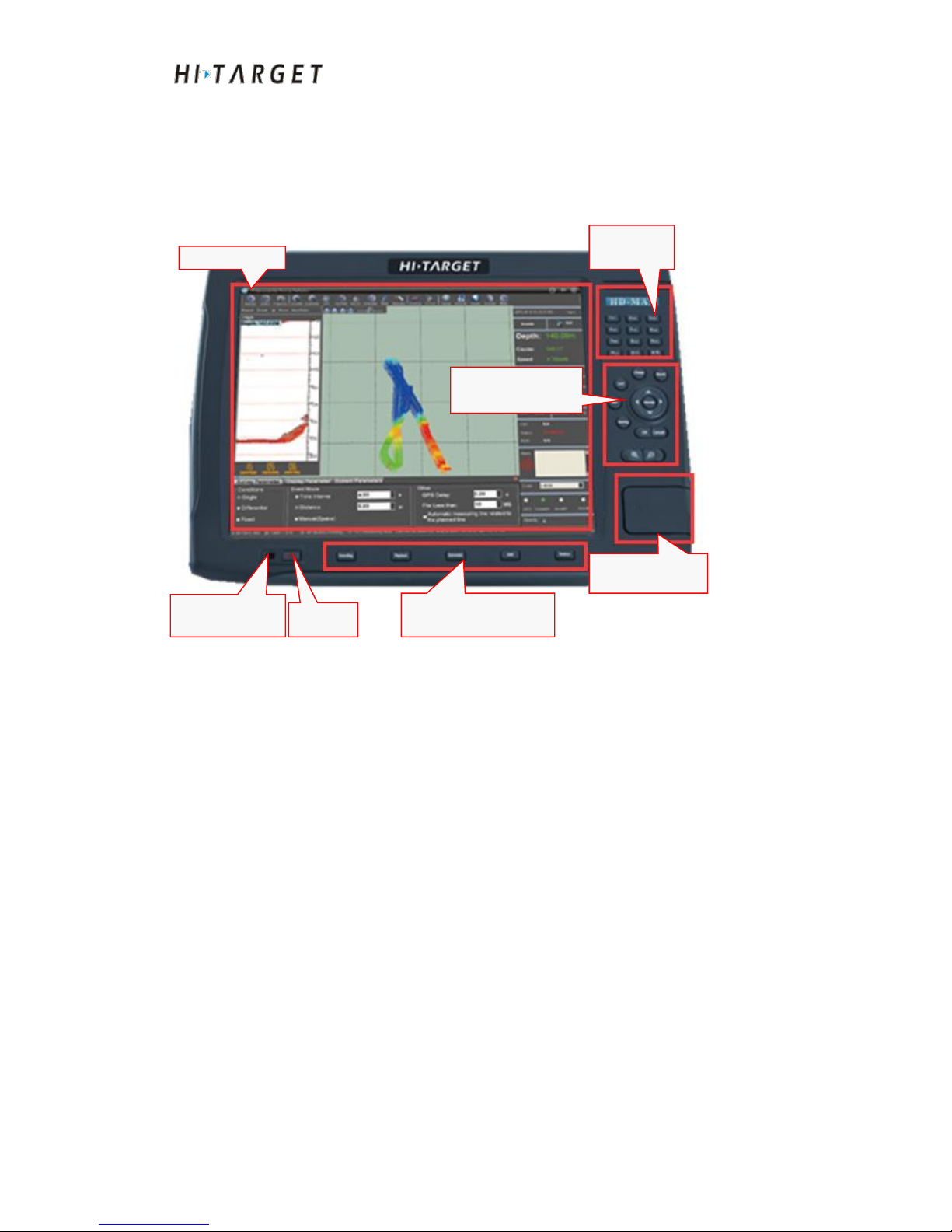
Front Face of the Host
The front face of the host is as shown in the Figure below. It is composed of
display screen, measuring functional keys area: digital keys area, sounding
functional keys area and USB interfaces area.
Figure 2-1
Display screen
17" TFT display screen to realize clear display as well as convenient
operation.
Measuring functional keys area
Include locking, line changeover, recording, marking and other commonly
used functional keys for measuring.
Sounding functional keys area
Include depth sounding, playback, automatically and other commonly used
functional keys for measuring.
USB interfaces area
Open the cover, you can see three USB interfaces available.
Display screen
Measuring function
keys area
Sounding functional
keys area
USB interface
area
On/off
Power indicator
light
Digital
keys area
HD-MAX Echo Sounder User Guide
14
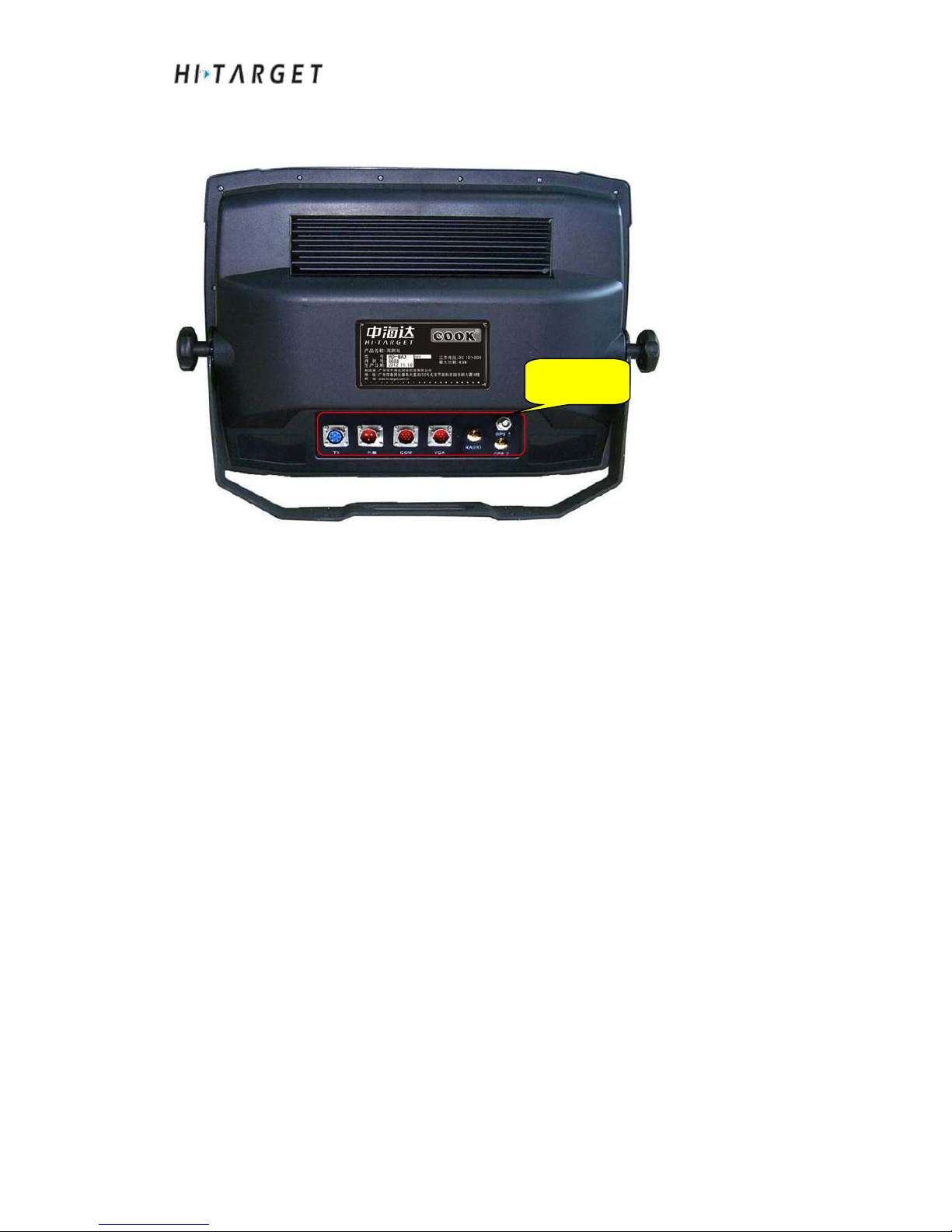
Back Face of the Host
Figure 2-2
The back interfaces of HD-MAX series products include DC10-30V power
interface, high frequency transducer interface, serial data transport interface
(SDTI), VGA display output interface and GPS antenna interface.
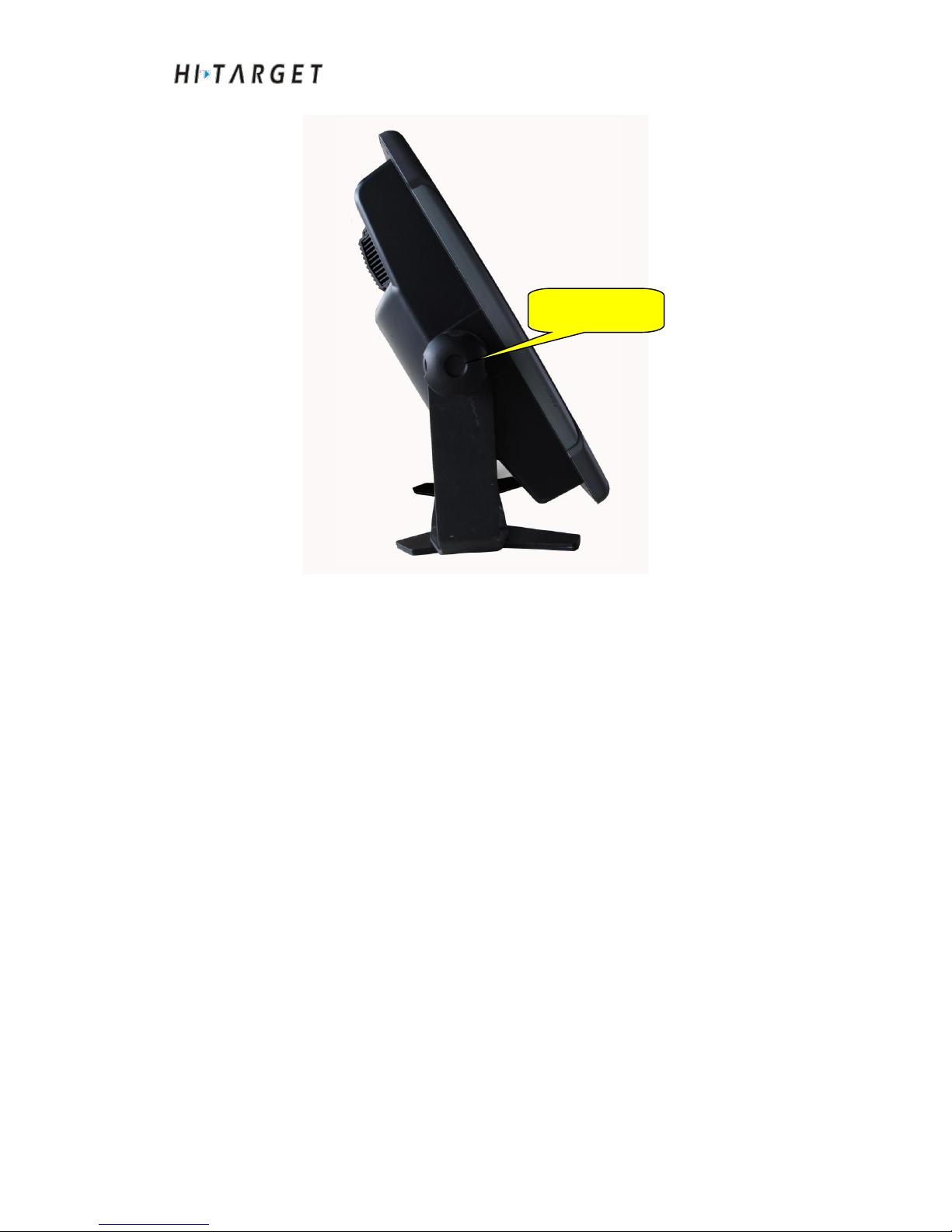
Side Faces of the Host
Back
interfaces
HD-MAX Echo Sounder User Guide
15
Figure 2-3
As shown in Figure 2-3, after fixed, the bracket can support the host. The
angle of the bracket can be adjusted randomly by loosening bracket screws.
Other Accessories
Keyboard
The product is equipped with portable and convenient p-p USB interface
keypad which is characterized by good stability, exquisite appearance,
flexible use, as well as excellent hand feeling. It is easy for operation on the
ship.
Mouse
The product is equipped with p-p USB interface mouse with good stability. It
is easy for operation on the ship.
AC power adapter
Bracket fixing
screw

HD-MAX Echo Sounder User Guide
16
Figure 2-4
The instrument has a wide input voltage range. It can be applied for 10~30V
DC (nominal input voltage: DC24V) power supply. The standard output is
20V.
High frequency transducer
Figure 2-5
The high frequency transducer is to connect 7 core socket in back interface
board of HD-MAX product.
Receiving antenna 1

HD-MAX Echo Sounder User Guide
17
Figure 2-7
The antenna is to connect to ANT POS at rear interface board of HD-MAX
products to receive GPS signal. (GPS measuring version of HD-MAX series
products)
VGA patch cord
Figure 2-10
VGA patch cord is used to connect external computer monitor for sub-screen
display.

HD-MAX Echo Sounder User Guide
18
Second full serial port serial port line
Figure 2-11
Second full serial port serial port line is used to external connected to two
RS-232 serial ports
DC power supply cable
Figure 2-12
Host installation size chart
Equipment shell size is as shown in Figure 2-7:

HD-MAX Echo Sounder User Guide
19
Figure 2-13
Installation Cautions
a) Avoid direct sunlight and high temperature. Avoid strong vibration.
b) Do not plug nor unplug the power when powered on. It is more possible to
facility a DC stabilized power supply of 10-30V.
c) Confirm that there is enough space behind the host in order to install the
plug and cable.
d) Non-professional personnel shall not disassemble the equipment. For any
question, please contact the retailer as soon as possible.

HD-MAX Echo Sounder User Guide
20
C H A P T E R
3
Basic operations
Introduction to this Chapter
■ Buttons
■ Keyboard
■ Startup & Shutdown
■ USB Interface
■ Rear panel Interface
Table of contents
Popular Marine Equipment manuals by other brands

Zeta Alarm Limited
Zeta Alarm Limited MKII-AXTB/R installation manual

SIAM
SIAM DU-1 operating manual

Cooper Notification
Cooper Notification ELUXA installation instructions

Webasto
Webasto BlueSky operating instructions

allpa
allpa TWIN DISC TECHNODRIVE MC 60 A Service manual

Yacht Devices
Yacht Devices YDTC-13 user manual

Blink Marine
Blink Marine POWERTRACK user manual

Cellofoam
Cellofoam PERMAPORT XPRESS Assembly, installation and maintenance instructions

Furuno
Furuno T-2000 Operator's manual

SIM
SIM 2W-SIROUT-S installation manual

FLEXPRIN
FLEXPRIN APOLLO-6 user manual

Bennett Marine
Bennett Marine Lenco-to-BOLT instructions


