Allen-Bradley PowerFlex 755T User manual

Installation Instructions
Original Instructions
PowerFlex 755T Frames 5 and 6 Marine Discharge Kits
Catalog Numbers
20-750-CMRN-F5, 20-750-CMRN-F6
Product Advisories
Required Tools
Topic Page
Product Advisories 1
Required Tools 1
Frame 5 Marine Discharge Module and Conduit Box Kit Contents (Cat. No. 20-750-CMRN-F5) 2
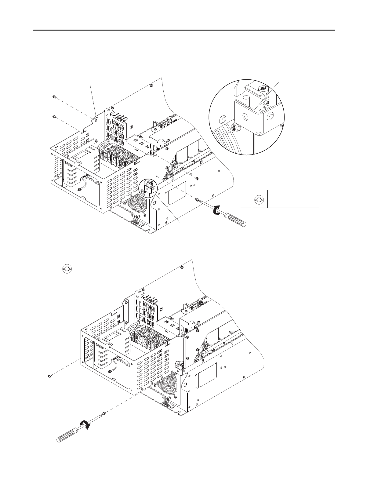
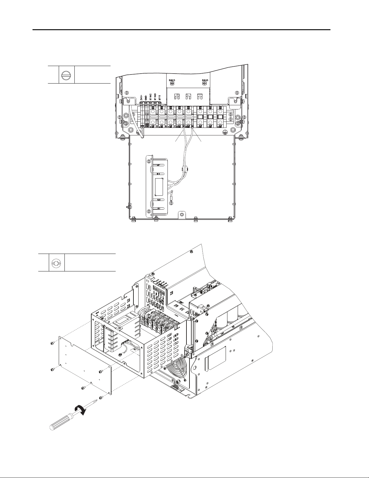
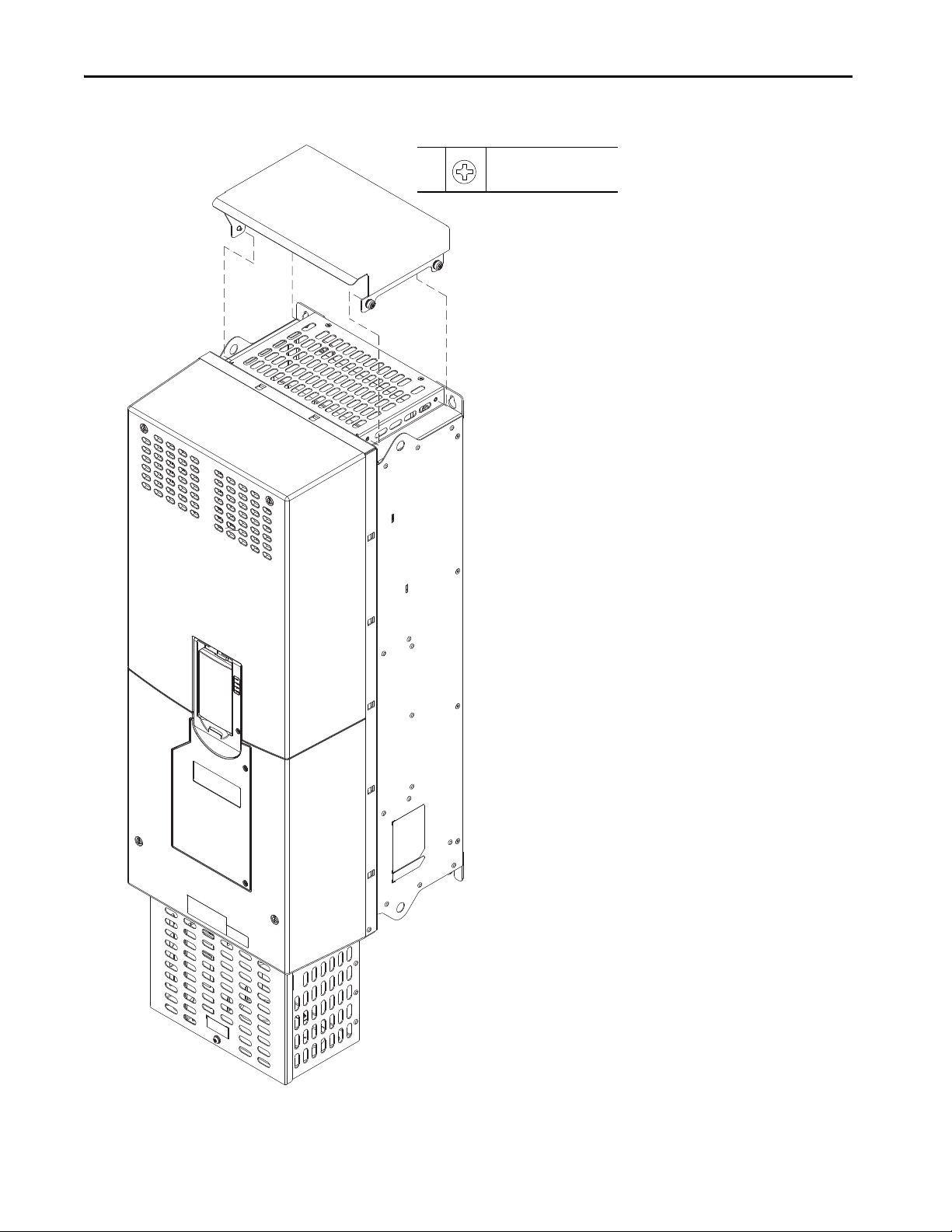
Frame 5 Marine Discharge Module Installation 3
Frame 6 Marine Discharge Module Kit Contents (Cat. No. 20-750-CMRN-F6) 10
Frame 6 Marine Discharge Module Installation 10
Additional Resources 15
ATTENTION: Only qualified personnel, who are trained and approved to install PowerFlex® 755T products and familiar with associated machinery, should plan or
implement the installation, startup, and subsequent maintenance of the system. Failure to comply can result in personal injury and/or equipment damage.
ATTENTION: The information that is contained in this publication is merely a guide for proper installation. Rockwell Automation®, Inc. cannot assume
responsibility for the compliance or the noncompliance to any code, national, local or otherwise for the proper installation of this drive or associated equipment.
A hazard of personal injury and/or equipment damage exists if codes are ignored during installation.
ATTENTION: This product contains Electrostatic Discharge (ESD) sensitive parts and assemblies. Static control precautions are required when you install these
assemblies. Component damage can result if ESD control procedures are not followed. If you are not familiar with static control procedures, reference any
applicable ESD protection handbook.
Tool Description Details
Allen (hex) socket wrench 4 mm
Electric drill and bits (Bit sizes to meet conduit size requirements)
Flat-nose screwdriver 6.4 mm (0.25 in.)
Torx, star, or hexalobular screw driver/bit #20, #25, #30
Torque wrench 1...12 N•m (8.8…106 lb•in)
Torque wrench 6...50 N•m (53…443 lb•in)

2Rockwell Automation Publication 750-IN114A-EN-P - July 2019
PowerFlex 755T Frames 5 and 6 Marine Discharge Kits
Frame 5 Marine Discharge Module and Conduit Box Kit Contents (Cat. No. 20-750-CMRN-F5)
The frame 5 marine discharge module and conduit box kit contains the following components. The debris hood is only required for IP20 Type 1
installations.
Item Quantity Description Item Quantity Description
1 1 Conduit box bottom plate 5 2 M6 x 12 mm torx screws (for conduit box)
2 5 M5 X 10 slotted-torx screws (for conduit bottom plate) 6 1 Conduit box cover
3 1 Conduit box and marine discharge module 7 1 M6 x 12 mm torx screw
4 4 M5 x 10 mm slotted-torx screws (for conduit box) 8 1 Debris hood with captive screws
Conduit Box and Marine Discharge Module
Debris Hood
1 2 3 4
5 6 7 8

Rockwell Automation Publication 750-IN114A-EN-P - July 2019 3
PowerFlex 755T Frames 5 and 6 Marine Discharge Kits
Frame 5 Marine Discharge Module Installation
Follow these steps to install the frame 5 marine discharge module and conduit box.
1. Use the pilot holes in the conduit box bottom plate to drill the required holes for control and input/output power wire conduit fittings.
2. Turn off and lockout all input power, including any external power sources.
3. Wait 5 minutes and remove the box conduit cover, if present.
4. Measure the AC input and DC bus voltage to verify that there is not voltage present. See Frame 5 Drive Terminal Identification on page 4
for terminal locations:
• Measure the AC input terminals R/L1, S/L2, and T/L3, L to L, and L to chassis GND (PE).
• Measure the DC output terminals +DC and –DC, +DC to –DC, +DC to chassis GND (PE), and –DC to chassis GND (PE).
WARNING: Remove power before you remove cables or make cable connections. When you remove or insert a cable connector with power applied, an electric
arc can occur. An electric arc can cause personal injury or property damage in theses ways:
• An electric arc can send an erroneous signal to system field devices, which can cause unintended machine motion
• An electric arc can cause an explosion in a hazardous environment
Electric arcs cause excessive wear to contacts on both the module and its mating connector. Worn contacts can create electrical resistance.
Pilot holes for control power
wire conduit fittings.
Pilot holes for input/output
power wire conduit fittings.

4Rockwell Automation Publication 750-IN114A-EN-P - July 2019
PowerFlex 755T Frames 5 and 6 Marine Discharge Kits
Frame 5 Drive Terminal Identifications
Item Name Description
1 PE grounding stud Termination point to chassis ground for the AC line shield
2 R/L1, S/L2, T/L3 AC line input power terminals.
3DC+, DC– DC bus terminals
4 U/T1, V/T2, W/T3 AC output motor terminals.
5 PE grounding stud Termination point to chassis ground for the motor shield.
1 2 3 4 5
Frame 5 shown with cover removed for clarity only.

Rockwell Automation Publication 750-IN114A-EN-P - July 2019 5
PowerFlex 755T Frames 5 and 6 Marine Discharge Kits
5. Loosen the four M4 captive screws that secure the cover to the assembly, and remove the cover.
4x
5
M4 (Captive)
F - 6.4 mm (0.25 in.) or 4 mm hex
2.6 N•m (23 lb•in)

6Rockwell Automation Publication 750-IN114A-EN-P - July 2019
PowerFlex 755T Frames 5 and 6 Marine Discharge Kits
6. Place the conduit box onto the chassis of the drive, so that the conduit box flanges are located on the inside of the drive chassis.
7. Insert and tighten the four M5 x 10 mm slotted-torx screws in the holes on the bottom sides of the chassis to secure the conduit box with
marine discharge module to the chassis.
8. Insert and tighten the two M6 x 12 mm torx screws in the holes on the bottom of the chassis to secure the conduit box to the chassis.
7
M5 x 10 mm
T25 or F - 6.4 mm (0.25 in.)
3.6 N•m (32 lb•in)
Conduit box flanges must be
inside the drive chassis.
See Detail A
Conduit box flanges must be
inside the drive chassis.
Detail A
7
M6 x 12 mm
T30
10.2 N•m (90 lb•in)

Rockwell Automation Publication 750-IN114A-EN-P - July 2019 7
PowerFlex 755T Frames 5 and 6 Marine Discharge Kits
9. Secure the DC+ wire from the marine discharge module to the small DC+ terminal on the drive.
10. Secure the DC- wire from the marine discharge module to the small DC– terminal on the drive.
11. Use five M5 x 10 mm slotted-torx screws to secure the bottom plate to the conduit box.
910
9, 10
M2.5
Flat
0.7 N•m (6.0 lb•in)
11
M5 x 10mm
T25 or F - 6.4 mm (0.25 in.)
3.6 N•m (32 lb•in)

8Rockwell Automation Publication 750-IN114A-EN-P - July 2019
PowerFlex 755T Frames 5 and 6 Marine Discharge Kits
12. Route the appropriate cables through the bottom plate of the conduit box and connect them to the appropriate input and output power
terminals.See the PowerFlex 750-Series Products with TotalFORCE® Control Installation Instructions, publication 750-IN100, for power
wiring information.
13. Configure the power jumpers according to the instructions in the Power Jumper Configuration section of the PowerFlex 750-Series
Products with TotalFORCE® Control Installation Instructions, publication 750-IN100.
14. Use one M6 x 12 mm slotted-torx screw to secure the front plate to the conduit box.
15. Secure the cover to the chassis as shown in step 5 on page 5.
13
M6 x 12 mm
T30
10.2 N•m (90 lb•in)

Rockwell Automation Publication 750-IN114A-EN-P - July 2019 9
PowerFlex 755T Frames 5 and 6 Marine Discharge Kits
16. For IP20 Type 1 installations only, place the debris hood on the top of the chassis and tighten the four M5 captive Phillips-head screws.
16
M5 (Captive)
P2
3.6 N•m (32 lb•in)

10 Rockwell Automation Publication 750-IN114A-EN-P - July 2019
PowerFlex 755T Frames 5 and 6 Marine Discharge Kits
Frame 6 Marine Discharge Module Kit Contents (Cat. No. 20-750-CMRN-F6)
The frame 6 marine discharge module kit contains the following components.
Frame 6 Marine Discharge Module Installation
Follow these steps to install the frame 6 marine discharge module.
1. Turn off and lockout all input power, including any external power sources.
2. Wait 15 minutes then remove the box conduit cover, if present.
3. Measure the AC input and the DC bus voltage to verify that there is no voltage present (see Frame 6 Drive and Bus Supply Power Terminal
Identification on page 11 for terminal locations):
• Measure the AC input terminals R/L1, S/L2, and T/L3, L to L and L to chassis GND (PE).
• Measure the DC output terminals +DC and –DC, +DC to –DC, +DC to chassis GND (PE), and –DC to chassis GND (PE).
Item Quantity Description
1 4 M4 nut and conical spring washer
2 1 Marine discharge module
WARNING: Remove power before you remove or make cable connections. When you remove or insert a cable connector with power applied, an electric arc can
occur. An electric arc can cause personal injury or property damage in theses ways:
• An electric arc can send an erroneous signal to system field devices, which can cause unintended machine motion
• An electric arc can cause an explosion in a hazardous environment
Electric arcs cause excessive wear to contacts on both the module and its mating connector. Worn contacts can create electrical resistance.
Marine Discharge Module
1 2

Rockwell Automation Publication 750-IN114A-EN-P - July 2019 11
PowerFlex 755T Frames 5 and 6 Marine Discharge Kits
Frame 6 Drive and Bus Supply Power Terminal Identification
Item Name Description Item Name Description
1 PE Grounding Stud Termination point to the chassis ground for the AC line shield 4 U/T1, V/T2, W/T3 AC output motor terminals
2 R/L1, S/L2, T/L3 AC line input power terminals 5 PE Grounding Stud Termination point to chassis ground for the motor shield
3+DC, –DC DC bus terminals —— —
21 543
Frame 6 Shown with the Cover Removed for Clarity Only.

12 Rockwell Automation Publication 750-IN114A-EN-P - July 2019
PowerFlex 755T Frames 5 and 6 Marine Discharge Kits
4. Loosen the eight M4 captive screws that secure the cover to the assembly, and remove the cover.
8x
4
M4 (Captive)
F - 6.4 mm (0.25 in.) or 4 mm hex
2.6 N•m (23 lb•in)

Rockwell Automation Publication 750-IN114A-EN-P - July 2019 13
PowerFlex 755T Frames 5 and 6 Marine Discharge Kits
5. Loosen the three M4 captive, slotted-torx screws that secure the fan power supply circuit board assembly to the chassis and lift the assembly
off the chassis to allow access to terminal block J27 on the power board.
5
M4 (Captive)
T20 or F - 6.4 mm (0.25 in.)
2.3 N•m (20 lb•in)
5
5

14 Rockwell Automation Publication 750-IN114A-EN-P - July 2019
PowerFlex 755T Frames 5 and 6 Marine Discharge Kits
6. Route the marine discharge module wire harness under the perforated plate and along the left side of the drive chassis.
7. Use four M4 hex nuts to secure the mounting bracket and marine bus conditioner to the chassis.
8. Connect the marine discharge module wire harness connector P27 to J27 on the power circuit board.
7
M4
7 mm
2.6 N•m (23 lb•in)
6. Route the wire harness under the perforated
mounting plate and along side of chassis.

Rockwell Automation Publication 750-IN114A-EN-P - July 2019 15
PowerFlex 755T Frames 5 and 6 Marine Discharge Kits
9. Replace the fan power supply circuit board assembly that was removed in step 5 on page 13 and secure the three M4 x 10 mm captive,
slotted-torx screws on the assembly to the chassis.
10. Configure the power jumpers according to the instructions in the Power Jumper Configuration section of the PowerFlex 750-Series
Products with TotalFORCE® Control Installation Instructions, publication 750-IN100.
11. Secure the cover to the chassis as shown in step 4 on page 12.
Additional Resources
These documents contain additional information concerning related products from Rockwell Automation.
You can view or download publications at http://www.rockwellautomation.com/global/literature-library/overview.page.
Resource Description
PowerFlex 750-Series Products with TotalFORCE® Control Installation Instructions,
publication 750-IN100
Provides the basic steps to install PowerFlex 755TL low harmonic drives, PowerFlex 755TR
regenerative drives, and PowerFlex 755TM drive systems.
PowerFlex 750-Series Products with TotalFORCE Control Technical Data, publication 750-TD100
Provides detailed information on:
• Drive and bus supply specifications
• Option specifications
• Fuse and circuit breaker ratings
PowerFlex 750-Series Products with TotalFORCE Control Hardware Service Manual,
publication 750-TG100
Provides detailed information on:
• Preventive maintenance
•Component testing
• Hardware replacement procedures
Industry Installation Guidelines for Pulse Width Modulated (PWM) AC Drives,
publication DRIVES-AT003
Provides basic information on enclosure systems, considerations to help protect against
environmental contaminants, and power and grounding considerations for installing Pulse
Width Modulated (PWM) AC drives.
Wiring and Grounding Guidelines for Pulse Width Modulated (PWM) AC Drives,
publication DRIVES-IN001 Provides basic information to properly wire and ground PWM AC drives.
Product Certifications website: rok.auto/certifications Provides declarations of conformity, certificates, and other certification details.
Rockwell Automation Knowledgebase The Rockwell Automation Support Forum

Allen-Bradley, PowerFlex, Rockwell Automation, Rockwell Software, and TotalForce are trademarks of Rockwell Automation, Inc.
Trademarks not belonging to Rockwell Automation are property of their respective companies.
Rockwell Otomasyon Ticaret A.Ş., Kar Plaza İş Merkezi E Blok Kat:6 34752 İçerenköy, İstanbul, Tel: +90 (216) 5698400
Rockwell Automation maintains current product environmental information on its website at http://www.rockwellautomation.com/rockwellautomation/about-us/sustainability-ethics/product-environmental-compliance.page.
*PN-541507*
PN-541507
Publication 750-IN114A-EN-P - July 2019
Copyright © 2019 Rockwell Automation, Inc. All rights reserved. Printed in the U.S.A.
Other manuals for PowerFlex 755T
4
This manual suits for next models
3
Table of contents
Popular Marine Equipment manuals by other brands

Standard Horizon
Standard Horizon MD150 owner's manual

Grammer
Grammer AVENTO Sports Line Suspension Kit operating instructions

Garmin
Garmin GHC 20 owner's manual

Connect-A-Dock
Connect-A-Dock myers 1000 Series Assembly instructions

Boxfish
Boxfish Grabber manual

AML Oceanographic
AML Oceanographic AML-3 LGR quick start guide