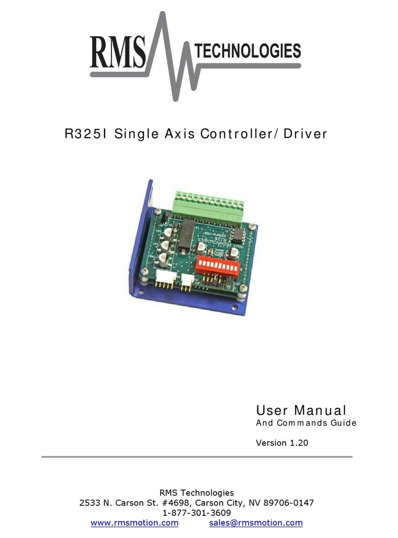
RMS R325P User manual

R325PSingleAxisDriver
UserManual
AndCommandsGuide
Version1.00
RMSTechnologies
2533N.CarsonSt.#4698,CarsonCity,NV89706‐0147

R325PUserManual Page2of20 1/31/2013Version1.0
ThankyouforpurchasingtheR325PSingle‐AxisStep&DirectionDriver.Thisproductis
warrantedtobefreeofmanufacturingdefectsforone(1)yearfromthedateofpurchase.
PLEASEREADBEFOREUSING
Beforeyoustart,youmusthaveasuitablestepmotor,aDCpowersupplysuitableforthemotor
andacurrentresistor.Thepowersupplyvoltagemustbebetween4timesand20timesthe
motor'sratedvoltage.
DISCLAIMER
Theinformationprovidedinthisdocumentisbelievedtobereliable.However,noresponsibility
isassumedforanypossibleinaccuraciesoromissions.Specificationsaresubjecttochange
withoutnotice.
RMSTechnologiesreservestherighttomakechangeswithoutfurthernoticetoanyproducts
hereintoimprovereliability,function,ordesign.RMSTechnologiesdoesnotassumeany
liabilityarisingoutoftheapplicationoruseofanyproductorcircuitdescribedherein;neither
doesitconveyanylicenseunderitspatentrights,northerightsofothers.
SpecialSymbols
IndicatesaWARNINGandthatthisinformationcouldpreventinjury,lossof
property,orevendeath(inextremecases).

R325PUserManual Page3of20 1/31/2013Version1.0
R325PUserManual
Product:R325P
Version:1.00
Date:1/31/2013
VersionHistory
VersionDateDescriptionofChanges
1.0001/31/2013NewUserManual

R325PUserManual Page4of20 1/31/2013Version1.0
TableofContents
1.FEATURES ...........................................................................................5
2.ELECTRICALSPECIFICATIONS ......................................................................5
3.OPERATINGSPECIFICATIONS ......................................................................6
4.MECHANICALSPECIFICATIONS ....................................................................6
6.CONNECTIONSPECIFICATIONS ....................................................................8
ConnectingthePower ................................................................................................ 9
ConnectingtheMotor ................................................................................................ 9
ConfiguretheR325usingtheDIPSwitch.......................................................................... 10
DIPSwitchRunCurrentSettings ..............................................................................................10
DIPSwitchHoldCurrentSettings .............................................................................................11
DIPSwitchStepResolutionSettings..........................................................................................11
8.COMMANDTABLES ..............................................................................11
AxisConfigurationCommands..................................................................................... 11
GeneralOperationCommands..................................................................................... 11
9.COMMANDS ......................................................................................13
ProtocolSyntax ..................................................................................................... 13
10.Troubleshooting.................................................................................14
11.AppendixA......................................................................................15
11.AppendixB......................................................................................19

R325PUserManual Page5of20 1/31/2013Version1.0
1.FEATURES
SingleAxisDriverforBipolarstepmotors
Operatesfrom+12to48VDC
Phasecurrentsfrom0.3to3.0AmpPeak
NOTE:Phasecurrentof2.7AmpandaboveREQUIRESanadditionalheatsink,
makesurethetemperatureofthebracketdoesnotexceed45°C.
Holdcurrentreductioncapabilitywithadjustablecurrentandtimeoutsettings
SelectableStepResolutionfromFullStepto256xMicrostepping
Hasthreeopticallyisolatedcontrolinputsandoneopticallyisolatedcontroloutput
PoleDampingTechnology™integratedwithindriverboard
DipswitchesandaRS485interfacearebuilt‐intotheR325PController.AUSBconnectioncan
beusedbyusingtheUSB485ConverterCard(soldseparately).
2.ELECTRICALSPECIFICATIONS
SupplyVoltage: +12to48VDC
PhaseCurrent:0.3to3.0AmpsPeak
NOTE:Phasecurrentof2.7AmpandaboveREQUIRESanadditionalheatsink,
makesurethetemperatureofthebracketdoesnotexceed45°C.
I/OSpecifications
3xOpticallyIsolatedInputs(1fixed)
1xOpticallyIsolatedOutput
MinimumMotorImpedance:1.5mH
Note:Thedrivemaybehaveunpredictablyifthemotoryouareusinghasaninductanceless
than1.5mH.

R325PUserManual Page6of20 1/31/2013Version1.0
3.OPERATINGSPECIFICATIONS
MaximumStepFrequency: 2.5MHz
OperatingTemperature: Lowend–0°C
Highend–Dependentoncasetemperature,bracket
temperaturemustnotexceed45°C
AutomaticMotorHoldingCurrentreductionavailablefrom0.3to2.5Amps
LogicTiming
MinimumStepPulseWidth 200nanoseconds
MinimumStepLowTime 200nanoseconds
MaximumPower‐DownRecoveryTime20milliseconds
4.MECHANICALSPECIFICATIONS
Size:3.00”x2.75”x1.42”
Weight:3.2oz
Mounting:Four#6‐32screws,2.42”x2.45”
Plate:Aluminum,HardAnodized
Figure3.1

R325PUserManual Page7of20 1/31/2013Version1.0
5.PINASSIGNMENTS
MatingConnectors
P1Amp 640441‐3
P3PhoenixContact1803675
P1–RS485busInterface
P1Configuration
PinNoFunction
1AInput(+ve)
2Ground
3BInput(‐ve)
Table5.1
P1Connector–Pin1Location
Image5.1
P3–Motor/Controls/PowerInterface
A12‐pinpluggableterminalstripconnectorP3providespowerandthestepanddirection
controlfunctionsforthemodule.Allofthesesignalsareopticallyisolated.Open‐collectordrives
arerequiredtoprovidepulsesforStep,levelsforDirection,andDisable.Thecommon+ve
supplyrangesfrom5VDCto30VDCwithrespecttothesignalinput;howeverifthesupplyis
greaterthan5VDCthenaresistormustbeinsertedinserieswitheachsignallinetolimitthe
currentto10mA.
P3Configuration
PinNoFunction
1Common+veExternal
2Step(in)
3Direction(in)
4+5VDCInternal
5Disable(in)
6MotorA+(out)
7MotorA‐(out)
8MotorB+(out)
9MotorB‐(out)
10FullStepOutput
11PowerGround
12PowerPositive
Table5.2
P3Connector–Pin1Location
Image5.2

R325PUserManual Page8of20 1/31/2013Version1.0
CAUTION:ConnectingMotorphases(A,ABar,B,BBar)totheincorrectlocation
whiletheR325Pispoweredwillcausetheboardtoburn.Besuretoinsertmotor
phasesintoPins6through9,intheorderofA,ABar,B,andBBar.Itis
recommendedthatpowerisconnectedlast,sothatallconnectionscanbechecked
beforepowerup.
6.CONNECTIONSPECIFICATIONS
WhenusingtheDriverOnlyportionoftheR325P,usethedipswitchesforstepresolutionand
currentsettings.
UsingtheR325PasaDriverUnitOnly
IfusingtheR325PasaDriveronly,besuretoconnectthepowersupplylast.
Pin1:ConnectPin1toPin4tousetheinternal+5VDC.Byusingtheinternal+5VDCtheI/O’s
willnolongerbeopticallyisolated.Ifopticalisolationisstilldesired,useaseparate+5VDC
supplyandconnectthePOSITIVEendofthesupplytoPin1.TheNEGATIVEendwillconnect
withtheNEGATIVEendofyourpulsegenerator.
Pin2:UseapulsegeneratororfunctiongeneratortoreceivepulsesintotheR325P.Connect
thePOSTIVEendofthepulsegeneratortoPin2.TheNEGATIVEendwillbeconnectedtothe
NEGATIVEendofthe+5VDCsupplyifusingaseparatepowersource.Ifusingtheinternal
+5VDCsupply,connecttheNEGATIVEendofthepulsegeneratortoPowerGROUND.
Pin3:Toswitchthedirectionofmotorrotation,connectPin3withPin11,PowerGround.An
openorclosedconnectiontoPowerGroundwillchangethedirection.
Pin4:Thisistheinternal+5VDC.Usethisfortestingpurposesorifopticalisolationoftheinputs
isnotdesired.Itcanoutputamaxof50mAmps.
Pin5:ToenablethedriveleavethisPinopen,disablethedriveconnectPin5withPin11(Power
Ground).AnopenorclosedconnectiontoPowerGroundwillenableanddisablethedrive,
respectively.
Pin6:PhaseAMotorConnection
Pin7:PhaseAMotorConnection
Pin8:PhaseBMotorConnection
Pin9:PhaseBMotorConnection
CAUTION:ConnectingMotorphases
(A,ABar,B,BBar)totheincorrect
locationwhiletheR325Pispowered
willcausetheboardtoburn.Besure
toinsertmotorphasesintoPins6through9,in
theorderofA,ABar,B,andBBar.Itis
recommendedthatpowerisconnectedlast,so
thatallconnectionscanbecheckedbefore
powerup.
Pin10:TheFullStepoutputisnotavailableforthebasicR325P.Thisfeatureisusedonthe
R325PE.
Pin11:ConnecttheNEGATIVEofthePowerSupplytothisterminal.
Pin12:ConnectthePOSITIVEofthePowerSupplytothisterminal.(+12to48VDC)

R325PUserManual Page9of20 1/31/2013Version1.0
ConnectingthePower
TheR325Prequiresasupplyvoltagebetween12‐48VDC.First,connectthepositiveendofthe
powersupplytopositiveterminal(Pin12),andthenconnectthenegativeofthepowersupply
totheGround(Pin11)ontheR325P.
WARNING!Becarefulnottoreversethepolarityfromthepowersupplytothe
driver.Reversingtheconnectionwilldestroyyourdriverandvoidthewarranty.
ConnectingtheMotor
WARNING!MakesurethepowerisOFFwhenconnectingordisconnecting
motorsfromtheR325P.Damagewilloccurifthepowerisbeingsupplied.
Pleaserefertoyourmotordocumentationforwiringcolorcode.
ConnectthecorrespondingPhasefromthemotortotheproperpinontheR325P.
MotorPhase P1Connector
PhaseA Pin6
PhaseA‐ Pin7
PhaseB Pin8
PhaseB‐ Pin9
Figure6.1

R325PUserManual Page10of20 1/31/2013Version1.0
UsingtheR325Pwithmorethan5V
YoucanchoosetosupplytheoptoswiththeR325P’sinternal5Vsupplybyjumpingpins1to4.
Butifyouchoosetousemorethan5V,forexample,a24Vsupplyandthesteppulsetrainisalso
a0to24Vlow‐highsignal,pleaseusethefollowingrecommendedresistortolimitthecurrentto
10mAmps.Note:noresistorwillbeneededontheactualoptosupplyline,pin1.
Step&Directionlineshavea470ohminternalresistor
Voltage:5V10V15V24V
Ohmsneeded:050010002000
Wattagerating:0¼watt¼watt¼watt
Table6.1
Disablelinehasa1kohminternalresistor
Voltage:5V10V15V24V
Ohmsneeded:0100020003800
Wattagerating:01/8watt1/8watt¼watt
Table6.2
ConfiguretheR325PusingtheDIPSwitch
R325PDIPSwitchSettings
RunCurrent
FunctionSW1SW2SW3SW4
0.3AONONONON
0.4AOFFONONON
0.5AONOFFONON
0.6AOFFOFFONON
0.8AONONOFFON
1.0AOFFONOFFON
1.2AONOFFOFFON
1.4AOFFOFFOFFON
1.6AONONONOFF
1.8AOFFONONOFF
2.0AONOFFONOFF
2.2AOFFOFFONOFF
2.4AONONOFFOFF
2.6AOFFONOFFOFF
2.8AONOFFOFFOFF
3.0AOFFOFFOFFOFF
Table6.3
WARNING:Currentof2.7AmpandaboveREQUIRESanadditionalheatsink;make
surethetemperatureofthebracketdoesnotexceed45°C

R325PUserManual Page11of20 1/31/2013Version1.0
HoldCurrent(PercentofRunCurrent)
FunctionSW5SW6
0%ONON
33%OFFON
66%ONOFF
100%OFFOFF
Table6.4
StepResolution
FunctionSW7SW8SW9SW10
FullStep*OFFOFFOFFOFF
2XONOFFOFFOFF
4XONONOFFOFF
8XONOFFONOFF
16XONONONOFF
32XONOFFOFFON
64XONONOFFON
128XONOFFONON
256XONONONON
Table6.5
*ThepowermustbeturnedOFFwhenswitchinginandoutofFullStepmode.
7.COMMANDTABLES
AxisConfigurationCommands
FunctionQuery/NewCodeValueMinimumMaximumDefault
HoldTimeoutQ/NHTNumeric1005000500
PercentFastDecayQ/NPFNumeric032
Table7.1
GeneralOperationCommands
FunctionQuery/NewCodeValueMinimumMaximumDefault
FirmwareRev.QFRNumeric‐ ‐ ‐
Table7.2

R325PUserManual Page12of20 1/31/2013Version1.0
CommunicatingwiththeR325P
1. ConnectP1toPCviaRS485‐232ConverterCardorUSB485ConverterCard.
2. SetupHyperTerminalbyselectingcorrectCOMport
3. SettingsforHyperTerminalisasfollows:57600,8bits,None,1,None
4. TheR325PDriveronlyversionallowsforchangingtheholdtimeoutsettings,the
amountofmixeddecay,andtocheckthefirmwarerevisionlevel.
RS485‐232ConverterCard
Image7.1
USB485ConverterCard
Image7.2

R325PUserManual Page13of20 1/31/2013Version1.0
8.COMMANDS
ProtocolSyntax
CommandFormat:#<Address><Command><value><CR><LF>
Example:#AHT1000<CR><LF>
SetstheHoldTimeoutforDriverAto1000
Toqueryacommandusethefollowingformat
QueryFormat:#<Address><Command><CR><LF>
Example:#AFR<CR><LF>
QueriesDriverAforthecurrentFirmwareRevision
Theresponsewouldbeinthefollowingformat
ResponseFormat:*<Address><value>
Example:*AFR325100
R325Pfirmwarerevision1.00
<CR><LF>standfor"CarriageReturn"and"LineFeed"respectively.TheseareNOTcharactersto
betypedin.Fordirectkeyboardusers,thesevaluesareexecutedwhenthe"Return"keyis
pressed.Forprogrammers,a"CarriageReturn"and"LineFeed"(alsoknownasa"NewLine")
commandneedstobeexecutedaftereachcommand.
Command
(CaseSensitive)OperandExampleDescription
HT100‐5000#AHT100
SetstheHold
Timeoutto100
mS
HoldTimeout‐CommandorQuery,Default=500
‐Readsorsetsthetimeintervalinmillisecondsafteranymotor
movement,beforethemotorcurrentischangedfromRunCurrent
toHoldCurrent.
PF0‐3#APF1
SetsMixed
Modedamping
to48%
PercentFastDecay‐CommandorQuery,Default=2
‐AllowstheDampingModeofthedriverICtobeset.
0=SlowDecay
1=MixedMode15%
2=MixedMode48%
3=100%FastDecay
Theoptimumsettingwillvarywithmotorinductanceandsteprate;
howeverthedefaultMixedModesettingwillworkwithmostmotors
FR‐ #AFRFirmwareRevision‐QueryOnly
‐Returns3digitpartcodefollowedby3digitfirmwarerevision.
Reply:*AFR325100//R325Pfirmwarerevision1.00
SD‐ #ASDSaveData–Afteralldesiredchangeshavebeenmade,type#ASDin
ordertosavethedatatomemory.
LD‐ #ALDLoadDefaultSettings–Usedtorevertbacktodefaultsettings.
TI‐ #ATITestInputs–QueryOnly
‐Thiscommandwillreturnavaluewhichcorrespondstothe
ON/OFFsequenceofall3inputs

R325PUserManual Page14of20 1/31/2013Version1.0
9.Troubleshooting
R325Pisnotfunctioningcorrectly
TryputtingtheR325PintoTESTmodebyplacingajumperonPins3&4ofJ1asshownbelow.
ThemotorshouldtwitchbackandforthslightlyiftheR325Pisfunctioningproperly.
R325Pnotmovingthemotor(Step/Dip)
Verifythatthe5VisbeingsuppliedtoPin1.
TheR325Piscausingthemotortovibrateandjitterbackandforth
AretheMotorphasesswitched?BesuretocheckthatmotorwiresareconnectedtoPins6
through9,intheorderofA,ABar,B,BBar.Tocheckwhichwiresbelongtoonephase,takea
Metertomeasureresistancebetweenanytwowires.Ifthereisafinitevaluebetweentwoof
them,insertthewiresintopins6and7,ORpins8and9.Inserttheremainingtwowires
accordingly.
TechnicalSupport
ByTelephone:408‐919‐0200
(Monday‐Friday;8:00AM‐5:00PMPacific)
OntheWeb:www.linengineering.com
Ourtechnicalsupportgroupisgladtoworkwithyouinansweringyourquestions.Ifyoucannot
findthesolutiontoyourparticularapplication,or,ifforanyreasonyouneedadditional
technicalassistance,pleasecalltechnicalsupportat408‐919‐0200.

R325PUserManual Page15of20 1/31/2013Version1.0
10.AppendixA:RecommendedCable
RecommendedCableConfigurations:DCSupplytoDriver
Cablelength,wiregaugeandpowerconditioningdevicesplayamajorroleintheperformance
ofyourRMSTechnologiesDriverandMotor.
NOTE:ThelengthoftheDCpowersupplycabletotheDrivershouldnotexceed50feet.
ExampleA–CablingUnder50Feet,DCPower
ExampleAdemonstratestherecommendedcableconfigurationforDCpowersupplycabling
under50feetlong.Ifcablingof50feetorlongerisrequired,theadditionallengthmaybe
gainedbyaddinganACpowersupplycable.
CorrectAWGwiresizeisdeterminedbythecurrentrequirementpluscablelength.Pleasesee
theDriverSupplyCableAWGTableinthisAppendix.

R325PUserManual Page16of20 1/31/2013Version1.0
NOTE:TheserecommendationswillprovideoptimalprotectionagainstEMIandRFI.Theactual
cabletype,wiregauge,shieldtypeandfilteringdevicesusedaredependentonthecustomer’s
applicationandsystem.
DriverSupplyCableAWGTable
1Amp(Peak)
Length(Feet)102550*75*100*
MinimumAWG2020181816
2Amps(Peak)
Length(Feet)102550*75*100*
MinimumAWG2018161414
3Amps(Peak)
Length(Feet)102550*75*100*
MinimumAWG1816141212
*UsethealternativemethodsillustratedinExamplesBandC
whenthecablelengthis≥50feet.Also,usethesamecurrent
ratingwhenthealternateACpowerisused
DriverSupplyCableWireSize
NOTE:AlwaysuseShielded/TwistedPairsfortheDriverDCSupplyCable,theACSupplyCable
andtheDrivertoMotorCable.

R325PUserManual Page17of20 1/31/2013Version1.0
RecommendedCableConfigurations:DrivertoMotor
Cablelength,wiregaugeandpowerconditioningdevicesplayamajorroleintheperformance
ofyourDriverandMotor.
NOTE:ThelengthoftheDCpowersupplycablebetweentheDriverandtheMotorshouldnot
exceed50feet.
ExampleAdemonstratestherecommendedcableconfigurationfortheDrivertoMotorcabling
under50Feetlong.
CorrectAWGwiresizeisdeterminedbythecurrentrequirementpluscablelength.Pleasesee
theDrivertoMotorCableAWGTableinthisAppendix.
ExampleA‐CablingUnder50Feet,DrivertoMotor
Ifcablingof50feetorlongerisrequired,theadditionallengthcanbegainedbyaddingCommon
ModeLineFilters(2x)
*L≈0.5MH

R325PUserManual Page18of20 1/31/2013Version1.0
*0.5MHisatypicalstartingpointfortheCommonModeLineFilters.Byincreasingor
decreasingthevalueofLyoucansetthedraincurrenttoaminimumtomeetyour
requirements.
DrivertoMotorCableAWGTable
1Amp(Peak)5Amp(Peak)
Length(Feet)10255075100Length(Feet)10255075100
Minimum
AWG2020181816 Minimum
AWG1616141212
2Amp(Peak)6Amp(Peak)
Length(Feet)10255075100Length(Feet)10255075100
Minimum
AWG2018161414 Minimum
AWG1414141212
3Amp(Peak)7Amp(Peak)
Length(Feet)10255075100Length(Feet)10255075100
Minimum
AWG1816141212 Minimum
AWG1212121212
4Amp(Peak)
Length(Feet)10255075100
Minimum
AWG1816141212
DrivertoMotorSupplyCableWireSize
NOTE:TheserecommendationswillprovideoptimalprotectionagainstEMIandRFI.Theactual
cabletype,wiregauge,shieldtypeandfilteringdevicesusedaredependentonthecustomer’s
applicationandsystem.
NOTE:AlwaysuseShielded/TwistedPairsfortheDriverDCSupplyCable,theACSupplyCable
andtheDrivertoMotorCable.

R325PUserManual Page19of20 1/31/2013Version1.0
11.AppendixB:PFValue
Forapplicationsrequiringultimatesmoothnessofmotionandextremeaccuracy,theR325P
drivercanbeprogrammedviaRS485tochangethePercentFastDecayrate,or,thePFvalue.
ThePercentFastDecaydefaultis2,oramixedmodeof48%.
MixedmodeisadampingtechniquedonetothedriverIC.Thefollowingvaluesindicatethe
choicesforPercentFastDecay:
PFValues(0through3):
0=SlowDecay
1=MixedMode15%
2=MixedMode48%
3=100%FastDecay
Generallyspeaking,applicationsthatrunatslowspeedsarerecommendedtouseaPFvalueof
1orless.FastspeedsshoulduseaPFvalueof2ormore.SincethebestPFvalueisdependent
onthemotorwinding,loads,powersupplyvoltage,andotherfactors,itisbesttousean
oscilloscopeandacurrentprobedevicetoviewthecurrentwaveformandtrydifferentPF
values.ThefollowingexamplesshowgoodandbadwaveformswhenchoosingdifferentPF
values.
PFvalue1
Slowspeeds
Goodwaveform

R325PUserManual Page20of20 1/31/2013Version1.0
PFvalue3
Slowspeeds
Badwaveform
PFvalue1
Fastspeeds
Badwaveform
Table of contents
Other RMS Controllers manuals
Popular Controllers manuals by other brands
Genebre
Genebre 3264 quick start guide

ABB
ABB PSTX30 370 Series installation instructions
Murphy
Murphy Cascade CD101 Installation and operation manual
fluidra
fluidra Astral Pool SLX Light Connect Lite installation instructions
Johnson Controls
Johnson Controls M9220-GGx-3 series installation instructions
Carel
Carel FCR3 user manual
