Rhein-Nadel Automation GmbH 10
VT_BA_SLC500-EN_2019 / 02.10.2019 SJ
5.1. Tuning
The following graph shows the resonance curve of a linear feeder. This information is fundamental for understanding
the workings of a vibration system which is essentially made up of the vibrating masses, of a spring constant, and of
the resulting resonance frequency. In operation, the driving frequency of the current causes the system to vibrate.
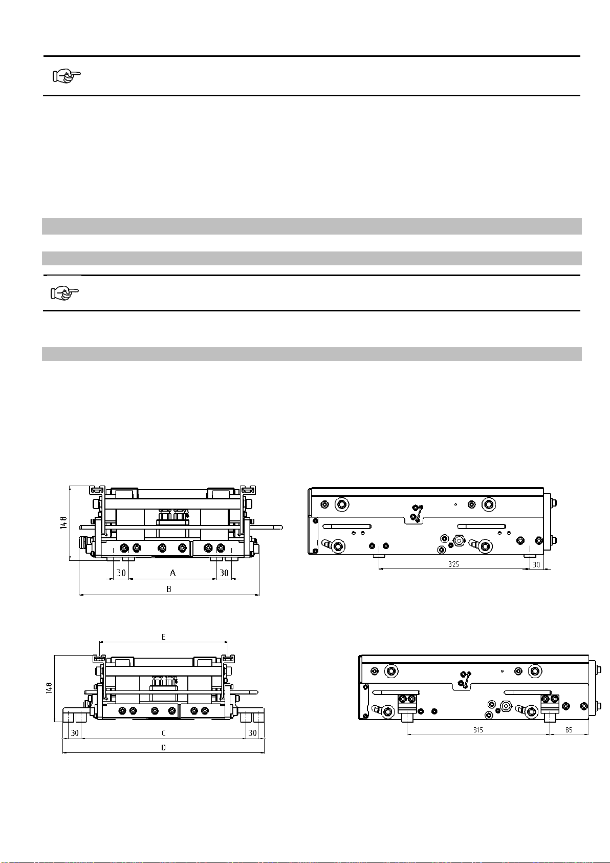
These vibrations propel the parts to be conveyed at the feed rate (A). In the case of a linear feeder, there are four pos-
sibilities to tune the vibration system:
1. Changing the masses of the vibratory unit and the counter mass. This changes the resonance frequency (C)
2. Changing the spring constant by adding or removing springs This changes the resonance frequency (C)
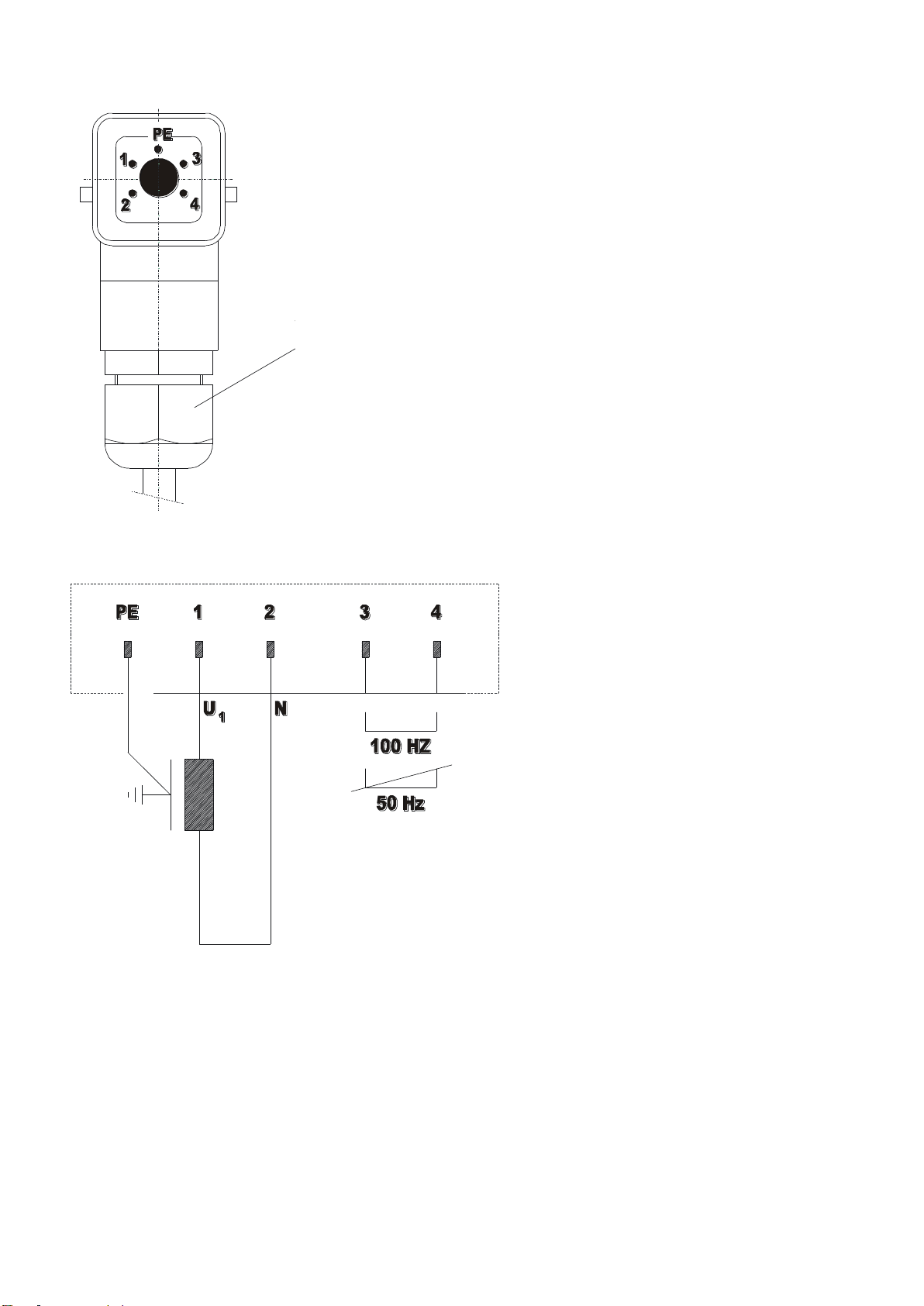
3. The driving frequency can be changed via the frequency controller (point on the curve)
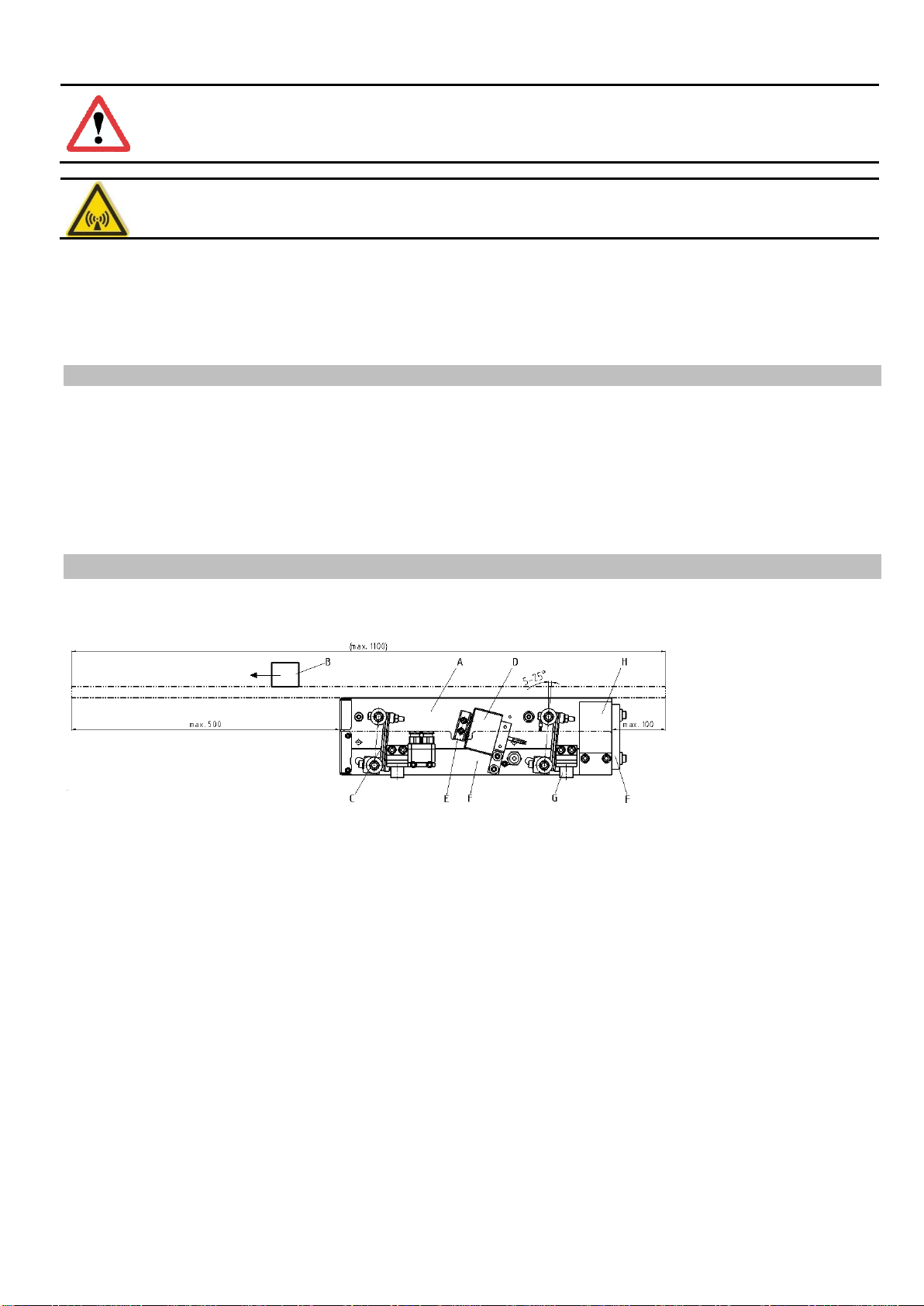
4. Adjustment of spring angle to obtain uniform feeder speed. (see section 5.3)
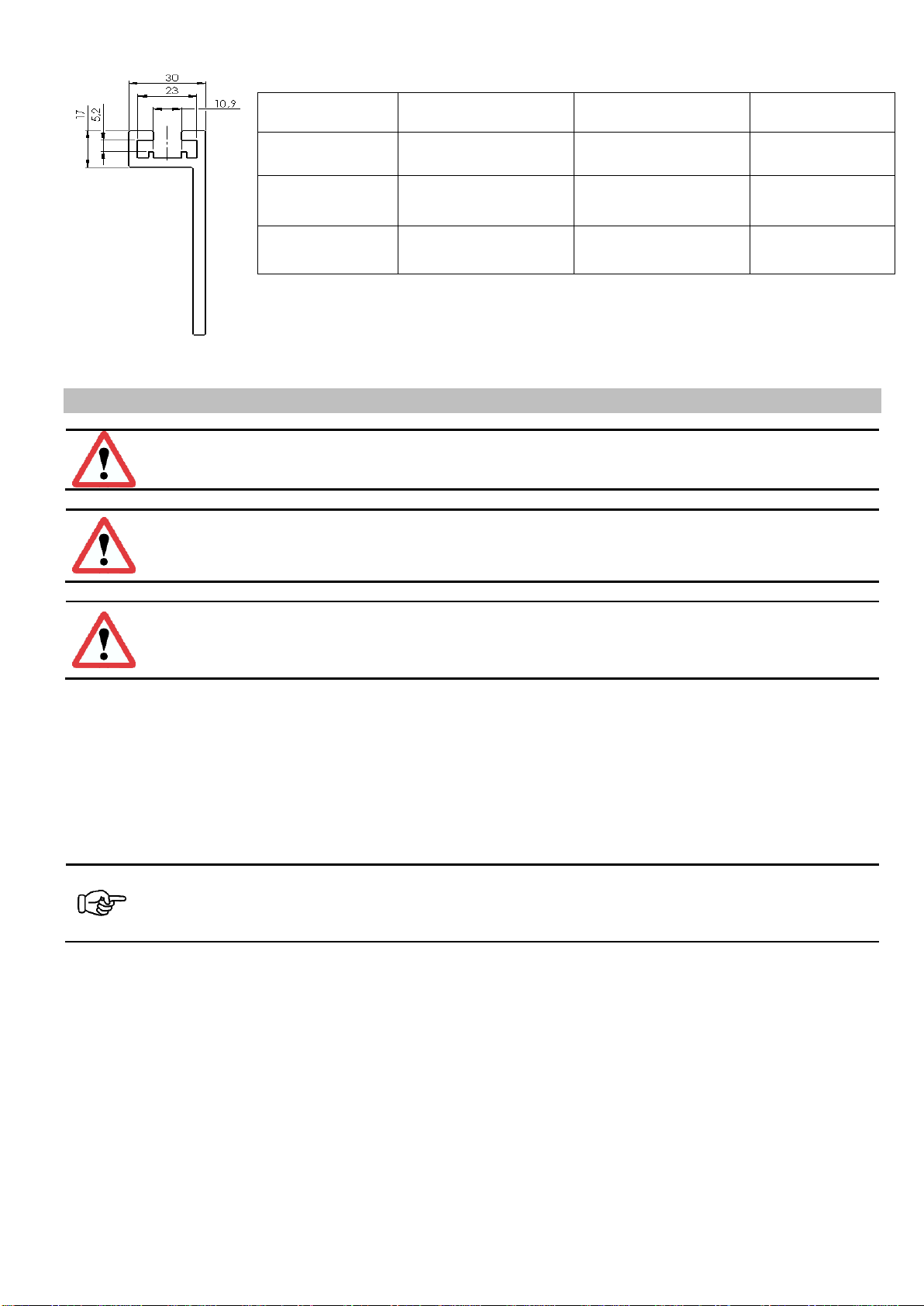
When changing springs, take into account that leaves of different thicknesses have different spring forces. As the
spring force increases to the square of spring thickness, please note the following examples:
•2.5 mm spring thickness = 6.25 spring force
•3.0 mm spring thickness = 9.0 spring force
•3.5 mm spring thickness = 12.25 spring force
One 3.5-mm thick leaf spring produces approximately the same spring force as two 2.5 mm thick leaf springs. It is al-
ways recommended, therefore, to perform the final adjustment / fine-tuning with thin leaf springs.
Notice
Changing the counter mass or the vibrating mass (by adding or removing counterweights or add-on
weights) will change the conveying speed or the natural frequency, respectively, of the linear feeder. If
necessary, leaf springs must be added or removed.
Optimum tuning is achieved when the desired feed rate is obtained with a controller setting of 80 %. In case of larger
deviations (> +/- 15%) you should re-tune the system.
The feeder sizes come factory-equipped with a spring set designed for a feed rail weight that is approx. 25% lower
than the maximum rail weight specified in the Technical Data (Section 1), and for a feeder speed of approx. 2 - 6
m/min.
If heavier or lighter feed rails are installed, or if much faster or slower feeder speeds are required, it will be necessary
to change either the natural frequency of the vibrating system, or the driving frequency. If you are using a compact
controller without frequency control (using 50 Hz mains power) it is mandatory to tune the system mechanically by
adding or removing springs.
In conjunction with frequency controllers (such as ESR 2000) it is usually possible to dispense with mechanical tuning
by adjusting the driving frequency on the controller.
The fundamentals and procedures of mechanical tuning and of frequency-based tuning are described below.
5.1.1. Mechanical tuning procedure for use with compact controller
If the feed rail assembly or the desired feed rate of a linear feeder deviate significantly from the values stated under
Technical Data, or if no frequency control unit is provided, the vibration system is tuned mechanically.
As a first step it is important to determine the current tuning region of the vibration system: either the natural frequen-
cy is less than 50 Hz or the natural frequency is higher than 50 Hz. To do this, you must determine the feeder
speed (using amplitude stickers) and then remove a counterweight while leaving all other settings/parameters un-
changed. Now you must measure the feeder speed again. The result and the procedure to follow are shown in the ta-
ble below:
Notice
The resonance frequency of the linear feeder must not coincide with the mains frequency (driving frequen-
cy). In most cases, it should be lower than this driving frequency.
A Feed rate
B Desired feeder speed
C Resonance frequency of the system
D Resonance curve
E Spring force (number of springs) increasing