RNA SLL 175 User manual

Operating instructions
Linear feeder
SLL 175
SLL 400
SLL 800
SLL 804
SLF 1000
and hopper type BV
BA
Rhein-Nadel Automation GmbH

Rhein - Nadel Automation GmbH Seite 2 Bedienungsanleitung Linearförderer Typ SLL / SLF
Table of content
1 Technical data page 2
2 Safety instructions page 6
3Construction and function of the linear feeder page 7
4 Transport and mounting page 7
5 Starting/ Adjustment page 8
6 Specifications for the design of the track page 11
7 Maintenance page 11
8 Stockkeeping of spare parts and after-sales service page 12
9 What to do, if....? page 12
Instructions for trouble-shooting
1 Technical data
Pin assignment
Notice
All linear feeders listed in the table may only be operated in connection with a RNA control unit at a
mains voltage of 230V/50Hz.. Special voltages and frequencies see separate data sheet.

Rhein - Nadel Automation GmbH Seite 3 Bedienungsanleitung Linearförderer Typ SLL / SLF
Linear feeder type SLL 175
Linear feeder type SLL 175-175 SLL 175-250
Dimensions L x B 2) x H (mm) 200x62x63 275x62x63
Weight 1,2 1,4
Insulation type IP54 IP54
Connecting cable length (m) 1.800 1.800
Power consumption 1) (VA) 16 16
Current consumption 1) (A) 70 mA 70 mA
Magnet nominal voltage 1) / Frequency (V / Hz) 200/50 200/50
Number of magnets 1 1
Magnet type WZAW010
Magnet colour black
Air gap (mm) 1,0 1,0
Vibration frequency Hz/min-1 100 Hz
Number of spring assemblies 2 2
Standard no. of springs
Number per spring assembly 1x1,25 / 1x1,5/
1x1,0 / 1x0,75 2x1,25 / 1x1,5/
1x1,0 / 1x0,75
Spring dimensions (mm)
Length (gauge for boreholes) x width 44,3(35)x26,7(12
) 44,3(35)x26,7(12
Spring size (mm) 0,75 – 1,5 0,75 – 1,5
Quality of the spring fastening screws 8.8 8.8
Tightening moment of the spring fastening screws 300 Ncm 300 Ncm
Max. weight of the oscillating units (linear track)
dependent on the mass moment of inertia and re-
quired running speed
1300 g
1500 g
Max. track length (mm) 325 400
Max. useful weight of the linear feeder dependent on
the mass moment of inertia and required running
speed
400 – 500 g
500 – 600 g
Linear feeder type SLL 400
Linear feeder type SLL 400 - 400 SLL 400 - 600 SLL 400 - 800 SLL 400 - 1000
Dimensions L x B 2) x H (mm) 430 x 84 x 103 630 x 84 x 103 830 x 84 x 103 1030x84x103
Weight 6,5 8 10 12,5
Insulation type IP 54 IP 54 IP 54 IP 54
Connecting cable length (m) 1,5 1,5 1,5 1,5
Power consumption 1) (VA) 120 120 120 120
Current consumption 1) (A) 0,6 0,6 0,6 0,6
Magnet nominal voltage 1) / Frequency (V / Hz) 200 / 50 200 / 50 200 / 50 200 / 50
Number of magnets 1 1 1 1
Magnet type WZAW 040
Magnet colour black
Air gap (mm) 1,0 1,0 1,0 1,0
Vibration frequency Hz/min-1 100 / 6.000
Number of spring assemblies 2 2 3 4
Standard no. of springs
Number per spring assembly 2 x 2,0
3 x 3,0 2 x 2,0
4 x 3,0 2 x 2,0
4 x 3,0 3 x 2,0
5 x 3,0
Spring dimensions (mm)
Length (gauge for boreholes) x width 70(56) x 40(18) 70(56) x 40(18) 70(56) x 40(18)
70(56) x 40(18)
Spring size (mm) 2,0 und 3,0 2,0 und 3,0 2,0 und 3,0 2,0 und 3,0
Quality of the spring fastening screws 8.8 8.8 8.8 8,8
Tightening moment of the spring fastening screws 15 Nm 15 Nm 15 Nm 15 Nm
Max. weight of the oscillating units (linear track)
dependent on the mass moment of inertia and required
running speed
ca. 5 kg
ca. 6 kg
ca. 7 kg
ca. 8 kg
Max. track length (mm) 700 900 1.100
1.300

Rhein - Nadel Automation GmbH Seite 4 Bedienungsanleitung Linearförderer Typ SLL / SLF
Max. useful weight of the linear feeder dependent on
the mass moment of inertia and required running
speed
1,5 – 2 kg
1,5 – 2 kg
1 - 1,5 kg
1 – 1,5 kg
Linear feeder type SLF 1000
Linear feeder type SLF 1000-1000 SLF 1000-1500
Dimensions L x B 2) x H (mm) 1.100 x 244 x 178 1.600 x 244 x 178
Weight 62 80
Insulation type IP 54 IP 54
Connecting cable length (m) 2 2
Power consumption 1) (VA) 504 1.004
Current consumption 1) (A) 2.51 5,0
Magnet nominal voltage 1) / Frequency (V / Hz) 200 / 50 200 / 50
Number of magnets 2 4
Magnet type YZAW 080
Magnet colour red
Air gap (mm) 2,5 2,5
Vibration frequency Hz/min-1 50 / 3.000
Number of spring assemblies 2 3 (4)³
Standard no. of springs
Number per spring assembly 8 x 3,5
12 x 3,5
Spring dimensions (mm)
Length (gauge for boreholes) x width 128(108) x 160(2x60) 128(108) x 160(2x60)
Spring size (mm) 3,5 3,5
Quality of the spring fastening screws 8.8 8.8
Tightening moment of the spring fastening screws 60 Nm 60 Nm
Max. weight of the oscillating units (linear track)
dependent on the mass moment of inertia and required
running speed
ca. 40 kg
ca. 70 kg
Max. track length (mm) 2.000 2.500
Max. useful weight of the linear feeder dependent on
the mass moment of inertia and required running
speed
20 – 30 kg
40 – 50 kg
1) At special connecting values (voltage/frequency see type plate at the magnet or vibrator
2) Width dimension for design b (= wide) 3) Spring assembly can be refit.
Linear feeder type SLL 800
Linear feeder type SLL 800 - 800 SLL 800 - 1000 SLL 800 - 1200 SLL 800 - 1400
Dimensions L x B 2) x H (mm) 850 x 120 x 162 1.050 x 120 x 162 1.250 x 120 x 162 1.450 x 120 x 162
Weight 18,5 kg 20,5 kg 23,5 kg 24,0 kg
Insulation type IP 54 IP 54 IP 54 IP 54
Connecting cable length (m) 2 2 2 2
Power consumption 1) (VA) 251 251 251 251
Current consumption 1) (A) 1,26 1,26 1,26 1,26
Magnet nominal voltage 1) / Frequency (V / Hz) 200 / 50 200 / 50 200 / 50 200 / 50
Number of magnets 1 1 1 1
Magnet type YZAW 080
Magnet colour red
Air gap (mm) 3,0 3,0 3,0 3,0
Vibration frequency Hz/min-1 50 / 3.000
Number of spring assemblies 2 2 2 2
Standard no. of springs
Number per spring assembly 1 x 2,5
5 x 3,5 1 x 2,5
5 x 3,5 1 x 2,5
6 x 3,5 1 x 2,5
6 x 3,5
Spring dimensions (mm)
Length (gauge for boreholes) x width 108(90) x 55(25) 108(90) x 55(25) 108(90) x 55(25) 108(90) x 55(25)
Spring size (mm) 2,5 ; 3,5 2,5; 3,5 2,5; 3,5 2,5; 3,5
Quality of the spring fastening screws 8.8 8.8 8.8 8.8
Tightening moment of the spring fastening screws 30 Nm 30 Nm 30 Nm 30 Nm
Max. weight of the oscillating units (linear track)
de
p
endent on the mass moment of inertia and
r
e
q
uired
ca. 11 kg
ca. 13 kg
ca. 15 kg
ca. 17 kg

Rhein - Nadel Automation GmbH Seite 5 Bedienungsanleitung Linearförderer Typ SLL / SLF
running speed
Max. track length (mm) 1.100 1.300 1.500 1.700
Max. useful weight of the linear feeder dependent on
the mass moment of inertia and required running
speed
4 - 8 kg
4 – 8
6 - 10
6 - 10
Linear feeder type SLL 800 - 1600 SLL 800 - 1800 SLL 800 - 2000 SLL 804 - 2400
Dimensions L x B 2) x H (mm) 1.650 x 120 x 162 1.850 x 120 x 162 2.050 x 120 x 162 2.450 x 120 x 172
Weight 31,5 34,0 39,5 63
Insulation type IP 54 IP 54 IP 54 IP 54
Connecting cable length (m) 2 2 2 2
Power consumption 1) (VA) 251 251 251 502
Current consumption 1) (A) 1,26 1,26 1,26 2,51
Magnet nominal voltage 1) / Frequency (V / Hz) 200 / 50 200 / 50 200 / 50 200 / 50
Number of magnets 1 1 1 2
Magnet type YZAW 080
Magnet colour red
Air gap (mm) 3,0 3,0 3,0 3,0
Vibration frequency Hz/min-1 50 / 3.000
Number of spring assemblies 3 3 3 4
Standard no. of springs
Number per spring assembly 2 x 2,5
7 x 3,5 2 x 2,5
7 x 3,5 2 x 2,5
9 x 3,5 2 x 2,5
14 x 3,5
Spring dimensions (mm)
Length (gauge for boreholes) x width 108(90) x 55(25) 108(90) x 55(25) 108(90) x 55(25) 108(90) x 55(25)
Spring size (mm) 2,5; 3,5 2,5; 3,5 2,5; 3,5 2,5; 3,5
Quality of the spring fastening screws 8.8 8.8 8.8 8.8
Tightening moment of the spring fastening screws 30 Nm 30 Nm 30 Nm 30 Nm
Max. weight of the oscillating units (linear track)
dependent on the mass moment of inertia and required
running speed
ca. 19 kg
ca. 21 kg
ca. 23 kg
ca. 51 kg
Max. track length (mm) 1.900 2.100 2.300 2.700
Max. useful weight of the linear feeder dependent on
the mass moment of inertia and required running
speed
6 – 10 kg
6 – 10 kg
6 – 10 kg
10 – 12 kg
1) At special connecting values (voltage/frequency see type plate at the magnet
2) Width dimension for design b (= wide)
Linear feeder type SLL 804
Linear feeder type SLL 804 - 800 SLL 804 - 1000 SLL 804 - 1200 SLL 804 - 1400
Dimensions L x B 2) x H (mm) 850 x 120 x 172 1.050 x 120 x 172 1.250 x 120 x 172 1.450 x 120 x 172
Weight 21,5 24,5 27,5 29,5
Insulation type IP 54 IP 54 IP 54 IP 54
Connecting cable length (m) 2 2 2 2
Power consumption 1) (VA) 251 251 251 251
Current consumption 1) (A) 1,26 1,26 1,26 1,26
Magnet nominal voltage 1) / Frequency (V / Hz) 200 / 50 200 / 50 200 / 50 200 / 50
Number of magnets 1 1 1 1
Magnet type YZAW 080
Magnet colour red
Air gap (mm) 3,0 3,0 3,0 3,0
Vibration frequency Hz/min-1 50 / 3.000
Number of spring assemblies 2 2 2 2
Standard no. of springs
Number per spring assembly 1 x 2,5
6 x 3,5 2 x 2,5
5 x 3,5 4 x 2,5
6 x 3,5 2 x 2,5
8 x 3,5
Spring dimensions (mm)
Length (gauge for boreholes) x width 108(90) x 55(25) 108(90) x 55(25) 108(90) x 55(25) 108(90) x 55(25)
Spring size (mm) 2,5 / 3,5 2,5 / 3,5
2,5 / 3,5 2,5 / 3,5
Quality of the spring fastening screws 8.8 8.8 8.8 8.8
Tightening moment of the spring fastening screws 30 Nm 30 Nm 30 Nm 30 Nm
Max. weight of the oscillating units (linear track)
de
p
endent on the mass moment of inertia and
r
e
q
uired
21 kg
25 kg
28 kg
32 kg

Rhein - Nadel Automation GmbH Seite 6 Bedienungsanleitung Linearförderer Typ SLL / SLF
running speed
Max. track length (mm) 1.100 1.300 1.500 1.700
Max. useful weight of the linear feeder dependent on
the mass moment of inertia and required running
speed
12 – 15 kg
12 – 15 kg
12 – 15 kg
12 – 15 kg
Linear feeder type SLL 804 - 1600 SLL 804 - 1800 SLL 804 - 2000 SLL 804 - 2800
Dimensions L x B 2) x H (mm) 1.650 x 120 x 172 1.850 x 120 x 172 2.050 x 120 x 172 2.850 x 120 x 172
Weight 39,5 43,0 49,5 76
Insulation type IP 54 IP 54 IP 54 IP 54
Connecting cable length (m) 2 2 2 2
Power consumption 1) (VA) 502 502 502 502
Current consumption 1) (A) 2,51 2,51 2,51 2,51
Magnet nominal voltage 1) / Frequency (V / Hz) 200 / 50 200 / 50 200 / 50 200 / 50
Number of magnets 2 2 2 2
Magnet type YZAW 080
Magnet colour red
Air gap (mm) 3,0 3,0 3,0 3,0
Vibration frequency Hz/min-1 50 / 3.000
Number of spring assemblies 3 3 3 4
Standard no. of springs
Number per spring assembly 4 x 2,5
9 x 3,5 4 x 2,5
9 x 3,5 4 x 2,5
11 x 3,5 2 x 2,5
14 x 3,5
Spring dimensions (mm)
Length (gauge for boreholes) x width 108(90) x 55(25) 108(90) x 55(25) 108(90) x 55(25) 108(90) x 55(2)
Spring size (mm) 2,5; 3,5 2,5; 3,5 2,5; 3,5 2,5; 3,5
Quality of the spring fastening screws 8.8 8.8 8.8 8.8
Tightening moment of the spring fastening screws 30 Nm 30 Nm 30 Nm 30 Nm
Max. weight of the oscillating units (linear track)
dependent on the mass moment of inertia and required
running speed
36 kg
40 kg
44 kg
ca. 62 kg
Max. track length (mm) 1.900 2.100 2.300 3.100
Max. useful weight of the linear feeder dependent on
the mass moment of inertia and required running
speed
12 – 15 kg
12 – 15 kg
12 – 15 kg
10 – 12 kg
1) At special connecting values (voltage/frequency see type plate at the magnet
2) Width dimension for design b (= wide)
2. Safety instructions
The conception and production of our linear feeders
has been carried out very carefully, in order to guar-
antee trouble-free and save operation. You too can
make an important contribution to job safety. There-
fore, please read this short operating instructions
completely, before starting the machine. Always ob-
serve the safety instructions!
Make sure that all persons working with or at this ma-
chine carefully read and observe the following safety
instructions!
This operating instruction is only valid for the types in-
dicated on the front page.
Notice
This hand points to information that
gives you useful tips for the operation of
the linear feeder.
Attention
This warning triangle marks the safety
instructions. Non-observance of these
warnings can result in serious or fatal in-
juries!
Dangers occuring at the machine
• The most dangerous parts of the machine are the
electrical installations of the linear feeder. In case
the linear feeder gets wet, there is the danger of an
electric shock!
• Make sure that the predector ground of the electric
power supply is in perfect condition!
Intended use
The intended use of the linear feeder is the actuation
of conveying tracks. These are used for linear trans-
port and feeding of correctly positioned mass-
produced parts, as well as for the proportioned feed-
ing of bulk material.
The intended use also includes the observance of the
operating and servicing instructions.
Please take the technical data of your linear feeder
from the table "technical data" (see chapter 1). Make
sure that the connected load of the linear feeder, con-
trol unit and power supply is compatible.
Notice
The linear feeder may only be operated
in perfect condition!
The linear feeder may not be operated in the explo-
sive or wet area.

Rhein - Nadel Automation GmbH Seite 7 Bedienungsanleitung Linearförderer Typ SLL / SLF
The linear feeder may only be operated in the configu-
ration drive unit, control unit and oscillating unit, as
specified by the manufacturer.
No additional loads may act upon the linear feeder,
apart from the material to be transported, for which
the special type is designed.
Attention
It is strictly prohibited to put any safety
devices out of operation!
Demands on the user
• For all activities (operation, maintenance, repair,
etc.) the details of the operating instructions must
be observed.
• The operator must avoid any working method
which would impair the safety of the linear feeder.
• The operator must take care that only authorized
personnel works at the linear feeder.
• The user is obliged to inform the operator immedi-
ately about any changed conditions at the linear
feeder that could endanger safety.
Attention
The linear feeder may only be installed,
put into operation and serviced by ex-
pert personnel. The binding regulation
for the qualification of electricians and
personnel instructed in electrical engi-
neering is valid, as defined in IEC 364
and DIN VDE 0105 part 1.
Attention:
Since the electromaget-field may have an im-
pact on persons arrying pacemakers it is rec-
ommended to keep a minimum distance of 25
cm.
Noise emission
The noise level at the place of operation depends on
the complete equipment and the material to be trans-
ported. The determination of the noise level according
to the EC-Regulations "Machinery" can therefore only
be carried out at the place of operation.
If the noise level at the place of operation exceeds the
limit permitted, noise predection hoods may be used,
which we offer as accessory parts (see catalogue).
Standards and regulations
The device was built according to the following stan-
dards and regulations:
• EC- Directive Machinery 98/37/EC
• EC- Low voltage directive 73/23/EC
• EMC- Directive 89/336/EC
• Applied harmonized Standards
EN 60204, T.1
EN 292, T.1 and T.2
• Applied national technical standards
VGB 4
VGB 10
• Rheinnadel- Conditions for purchasing
• VDE- Standards
• VDMA- Conditions of delivery
3 Construction and function of the
linear feeder
Linear feeders are used for the actuation of conveying
equipments. The actuation takes place by an electro-
magnet. The following schematic diagram shows the
function of a linear feeder:
A Conveying track and oscillating weight
B Material to be conveyed C Spring assembly
D Drive magnet E Armature
F Counterweight G Shock absorber
H Countermass
The linear feeder is a device of the familiy of vibratory
bowl feeders. It is, however, equipped with a linear
conveyor. Electromagnetic vibrations are converted
into mechanical vibrations and are used for conveying
material B. If magnet D, which is securely connected
with the countermass F, is supplied with current, it
generates a power that, dependent on the vibration
frequency of the mains supply, attracts and releases
armature E. Within a period of the 50 Hz of the A.C.
network the magnet achieves its maximum power of
attraction twice, as this is independent of the direction
of the current conduction. The vibration frequency
therefore is 100 Hz. In case a half-wave is locked, it is
50 Hz. Please take the vibration frequency of your lin-
ear feeder of the table "technical data" in chapter 1.

Rhein - Nadel Automation GmbH Seite 8 Bedienungsanleitung Linearförderer Typ SLL / SLF
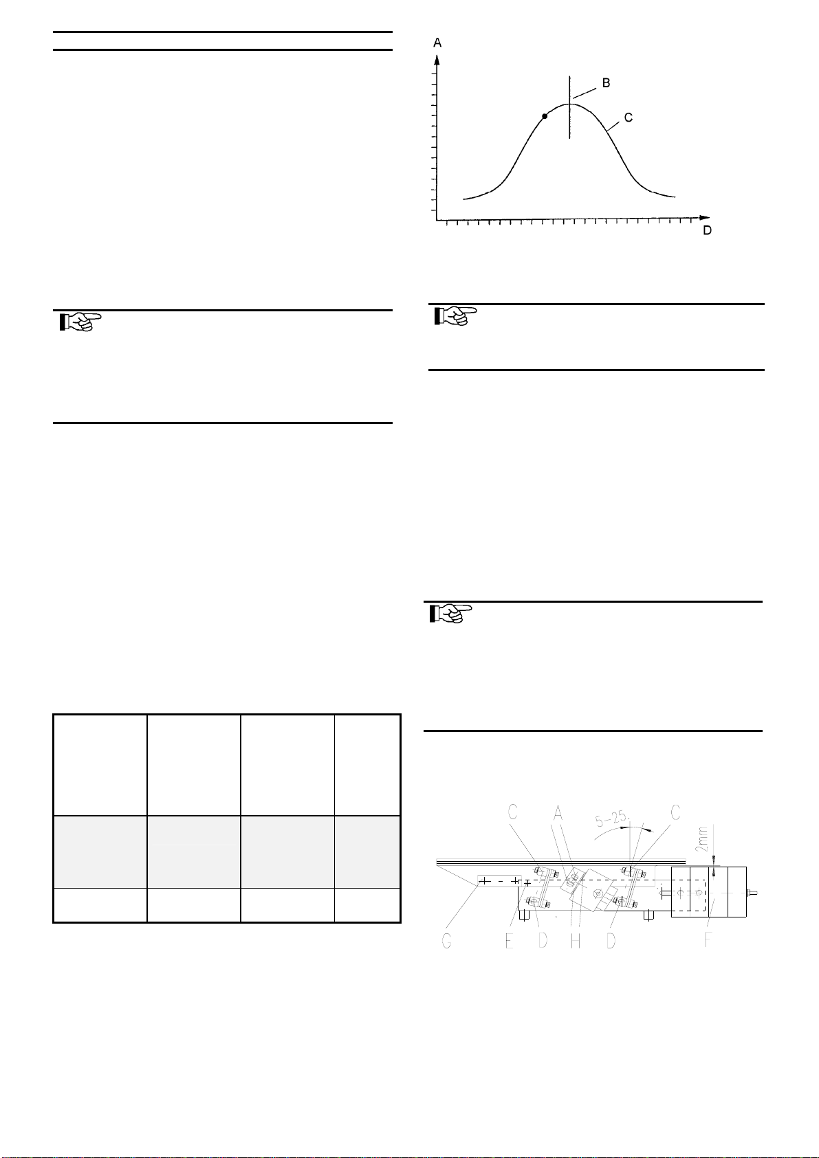
A linear feeder is a resonant system (spring-mass-
system). The result is that the adjustment made at the
factory will rarely meet your requirements. Chapter 5
describes in detail how your linear feeder is adapted
to your requirements.
Controlling of the linear feeder takes place by a low
loss electronic control unit type ESG N 80 or type
ESG 90. The control unit of the linear feeder is sepa-
rately delivered. At its front panel it is provided with a
7-pole plug-in connection, by which it is connected to
the linear feeder.
The pin assignment of the socket is shown in the table
"technical data" (chapter 1).
Notice
Detailed information on the complete
range of control units may please be taken
from the operating instructions for control
units..
All control units have got two main operating ele-
ments:
• By the mains switch the linear feeder is switched
on or off.
• By the turning knob the conveying capacity of the
transport unit is set.
4 Transport and mounting
Transport
Notice
Take care that the linear feeder cannot
dash against other things during transport.
The weight of the linear feeder is please taken from
the table "technical data" (chapter 1).
Mounting
The linear feeder should be mounted on a stable sub-
structure (available as an accessory part) at the place
where it is used. The substructure must be dimen-
sioned in a way that no vibrations of the linear feeder
can be carried away.
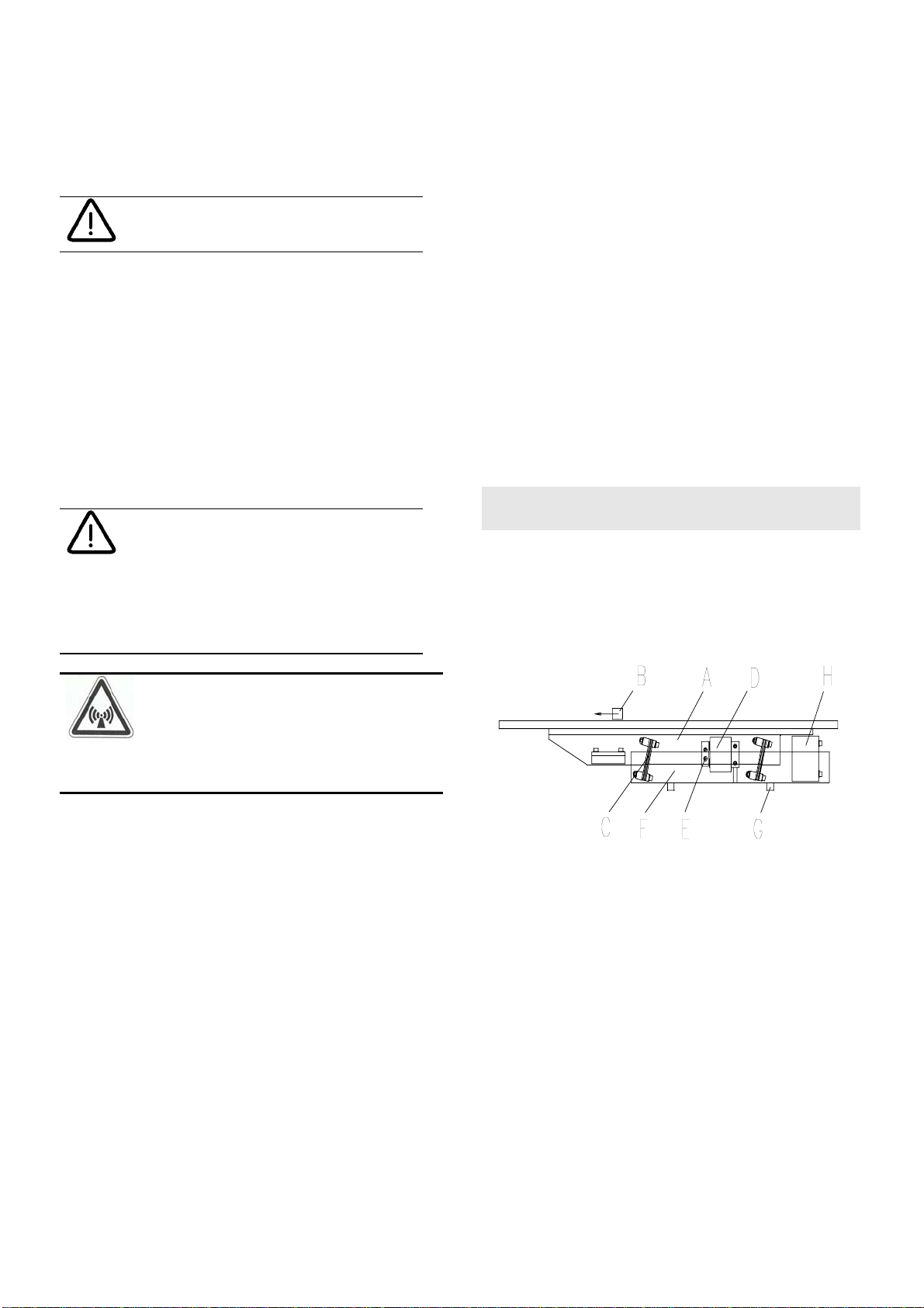
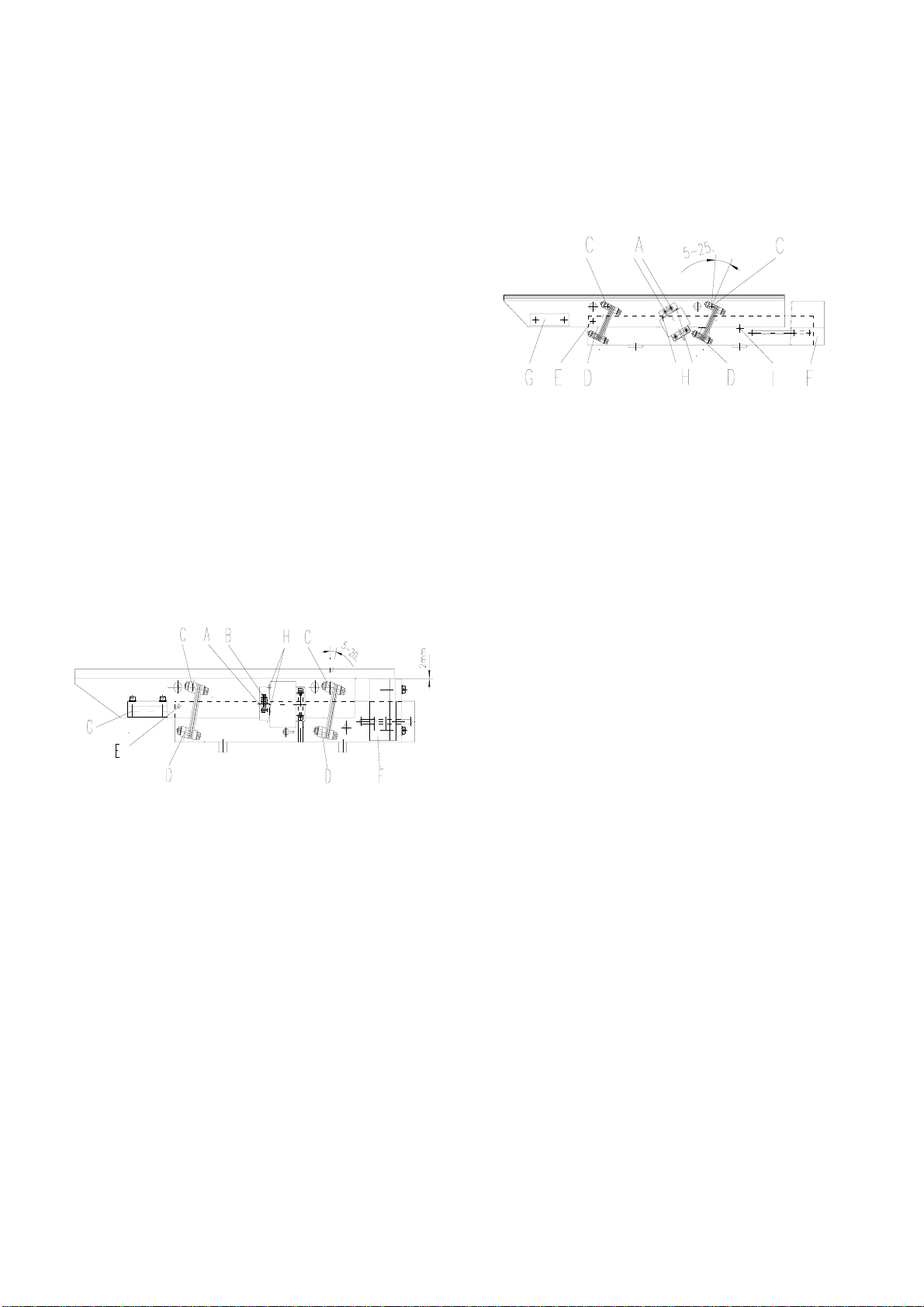
Linear feeders are fastened to the shock absorbers
from below (part G in the general drawing chap. 3).
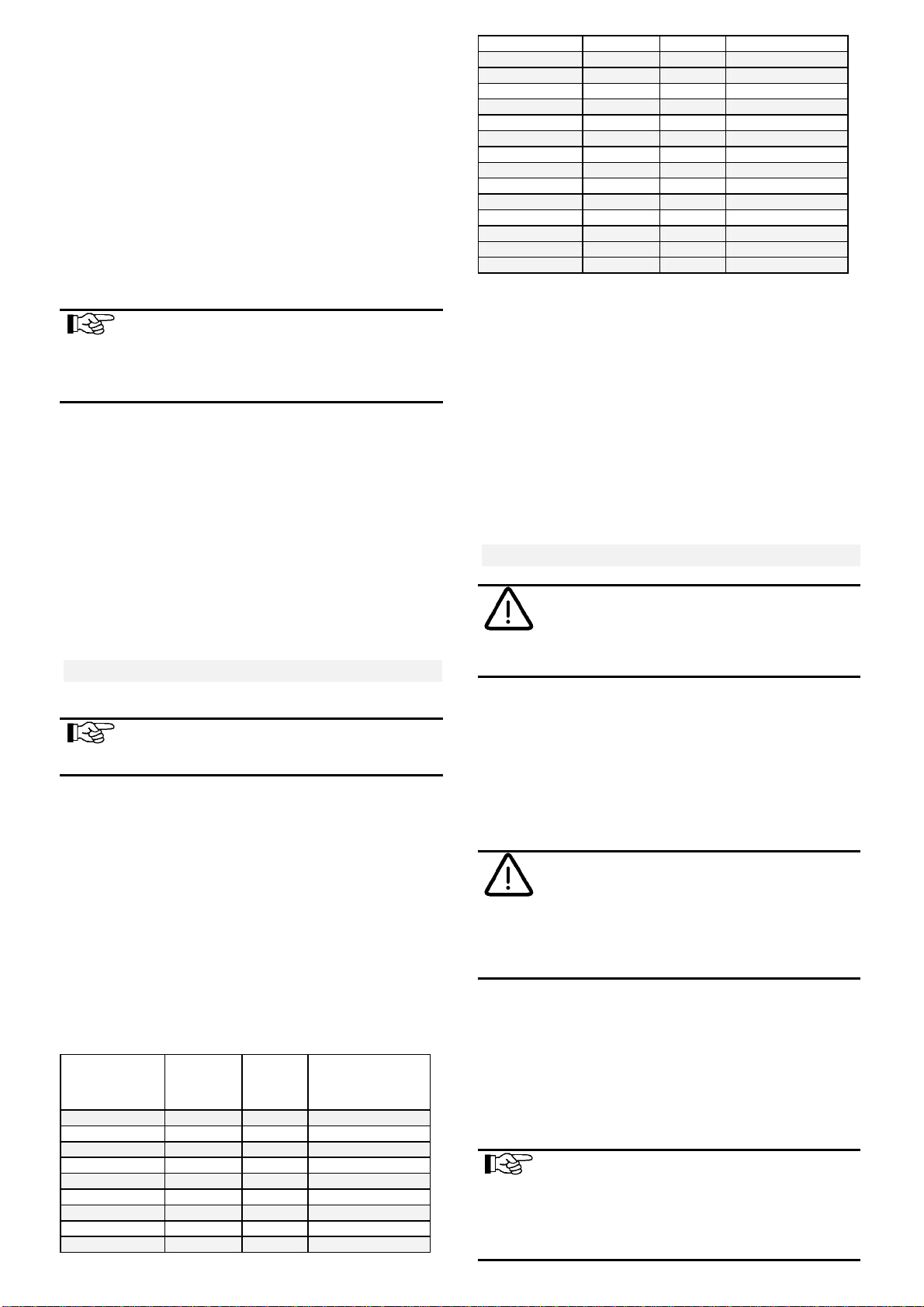
The following table will give you a summary of the
bore data of the various types:
Linear
feeder type Length
in mm Width
in mm Shock ab-
sorber
thread
SLL 175-175 125 37 M3
SLL 175-250 175 37 M3
SLL 400 - 400 200 60 M 4
SLL 400 - 600 300 60 M 4
SLL 400 - 800 450 60 M 4
SLL 400 - 1000 500 60 M 4
SLL 800 - 800 300 83 M 6
SLL 800 - 1000 450 83 M 6
SLL 800 - 1200 600 83 M 6
SLL 800 - 1400 750 83 M 6
SLL 800 - 1600 900 83 M 6
SLL 800 - 1800 1.050 83 M 6
SLL 800 - 2000 1.200 83 M 6
SLL 804 - 800 300 87 M 8
SLL 804 - 1000 450 87 M 8
SLL 804 - 1200 600 87 M 8
SLL 804 - 1400 750 87 M 8
SLL 804 - 1600 900 87 M 8
SLL 804 - 1800 1050 87 M 8
SLL 804 - 2000 1200 87 M 8
SLL 804 - 2400 1500 87 M 8
SLL 804 - 2800 1800 87 M 8
SLF 1000-1000 370 130 M 10
SLF 1000-1500 870 130 M 10
Tabelle: Bohrdaten
Make sure that the linear feeder cannot come into
contact with other devices during operation.
Further details on the control unit (bore plan, etc.) can
be taken from the operating instructions of the control
unit separately delivered.
5 Starting
Notice
Ensure that the frame ( stand, base, frame
etc.) is connected with the ground wire.
(PE) If necessary, predection earthing on
spot should be provided.
Check, whether
• the linear feeder stands in an isolated position and
does not come in securely with a solid body
• the linear track is screwed down and adjusted
• the connecting cable of the linear feeder is plugged
in at the control unit.
Attention
The electric connection of the linear feeder
may only be made by trained personnel
(electricians)! In case modifications are
made at the electric connection, it is abso-
lutely necessary to observe the operating
instructions "control units".
• The available supply voltage (frequency, voltage,
output) is in accordance with the connection data
of the control unit (see type plate at the control
unit).
Plug in the mains cable of the control unit and switch
on the control unit by the mains switch.
Notice
At linear feeders which are delivered as a
completely adjusted system, the optimal
conveying capacity is already set at the
factory. It is marked on the scale of the
turnin
g
knob with a red arrow. In this case

Rhein - Nadel Automation GmbH Seite 9 Bedienungsanleitung Linearförderer Typ SLL / SLF
set the turning knob to the marking..
The optimal operative range of the linear feeder is at a
controller position of 80% at the control unit. In case
of higher deviations (≥±15%) a readjustment should
be carried out.
5.2 Adjustment
with spring assemblies for a conveying track weight,
which is approx. 25 % lower than the maximum track
weight described in the Technical Data (chapt. 1), and
a running speed of 4 - 6 m/min. In case heavier or
lighter conveying tracks are installed or considerably
faster or slower conveying speeds are required, the
spring assemblies must be modified. For that the fol-
lowing basic rules have to be observed:
Notice
At first a rough adjustment of the convey-
ing speed (adjustment of the natural fre-
quency) must be made, which is followed
by the adjustment of the running behav-
iour. Finally you adjust the conveying
speed (natural frequency).
5.2.1 Adjusting the required running speed
In case the required running speed is not achieved
with the standard spring assembly, the current ad-
justment range of the oscillating system must at first
be found out, either natural frequency below 50 or
100 Hz or natural frequency above 50 or 100 Hz.
For that one or two plates are dismounted from the
movable counterweight for a trial. If a change in the
running speed on the conveying track is recognized, it
can be taken from the table below, whether springs
must be installed or removed. The controller position
at the control unit may not be changed during this
trial. In the factory the different sizes are equipped.
Change of the
running speed
on the convey-
ing track after
dismounting
the counter-
weight
Required run-
ning speed is
to be in-
creased
Required run-
ning speed is
to be reduced
Position
of the
natural
frequency
Slower Dismount
springs Install as many
springs as
needed to re-
duce the run-
ning speed
> 50 or
100 Hz
Faster Install springs Dismount
springs < 50 or
100 Hz
The following graphic chart shows the resonance
curve of a linear feeder:
A Conveying speed
B Natural frequency
C Resonance curve (not true to scale)
D Spring power (number of springs)
When exchanging the springs the valency of the vari-
ous leaf spring sizes must be considered. As the
spring size enters into the spring power in square, the
following examples must be ovserved:
• 2.5 mm spring size = 6.25 spring power
• 3.0 mm spring size = 9.0 spring power
• 3.5 mm spring size = 12.25 spring power
A 3.5 mm leaf spring has about the same valency as
two 2.5 mm leaf springs. For that reason it is recom-
mendable to carry out the final or fine adjustment al-
ways with thin leaf springs.
Notice
When changing the masses of counter and
oscillating weights (installation or dis-
mounting of counter or additional weights)
the running speed or the natural frequency
of the linear feeder is changed. If neces-
sary leaf springs must be added or re-
moved.
Changing the spring assembly for linear feeders
type SLL 400
Unscrew the 4 or 6 upper, lateral spring fastening
screws ("C)(M6 DIN 912). After that the complete vi-
brator with mounted track can be removed by lifting it
off. Dismount the required spring assembly by loosen-
ing the lower, lateral spring fastening screws
("D")(M6DIN912).
At the rear spring assembly the earthed conductor at
the upper spring seat must be unscrewed before the
Notice
The resonance curve of the linear feeder
may not correspond to the mains fre-
quency.

Rhein - Nadel Automation GmbH Seite 10 Bedienungsanleitung Linearförderer Typ SLL / SLF
spring assembly is dismounted. The dismounted
spring assembly must be horizontally clamped into a
parallel jaw vice with smooth clamping jaws, in order
to dismount or install the leaf springs. Between the
leaf springs washers must be mounted. Before tight-
ening the spring fastening screws both spring seats
must be aligned towards each other centrically and in
parallel. After that the spring fastening screws must
be tightened with a tightening torque of 15 Nm. Rein-
stall the complete spring assembly. In order to
achieve the previous position, two M6 screws, at
minimum 15 mm long, must be inserted into the ad-
justing bores at the upper countermass end ("E")
through countermass and oscillating profile and a 2
mm distance plate must be placed underneath in the
area of the counterweight and the vibrator at the linear
feeder's feeding side. After that the individual spring
assemblies can be screwed down in the required
spring angle with a tightening torque of 15 Nm. After-
wards the inserted screws and the distance plates
must be removed.
Changing the spring assembly for linear feeders
type SLL 800 und SLL 804
Unscrew the lower armature fastening screw ("A")(M6
DIN 912). Unscrew the 4 or 6 upper spring fastening
screws ("C")(M8DIN912). After that the complete vi-
brator with mounted track can be removed by lifting it
off. Dismount the required spring assembly by loosen-
ing the lower, lateral spring fastening screws
("D")(M8DIN 912).
At the rear spring assembly the earthed conductor at
the upper spring seat must be unscrewed before the
spring assembly is dismounted. The dismounted
spring assembly must be horizontally clamped into a
parallel jaw vice with smooth clamping jaws, in order
to remove or add the leaf springs. Between the leaf
springs washers must be mounted. Before tightening
the spring fastening screws the front locating edges of
the spring seats must closely fit to the leaf spring. The
short spring seat must be centrically adjusted be-
tween the vice jaws. After that the spring fastening
screws must be tightened with a tightening torque of
30 Nm. Reinstall the complete spring assembly. In or-
der to achieve the previous position, two M8 screws,
at minimum 20 mm long, must be inserted into the ad-
justing bores at the upper countermass end ("E")
through countermass and oscillating profile and a 2
mm distance plate must be placed underneath in the
area of the counterweight and the vibrator at the linear
feeder's feeding side. After that the individual spring
assemblies can be screwed down in the required
spring angle with a tightening torque of 30 Nm. After-
wards the inserted screws and the distance plates
must be removed.
Changing the spring assembly for linear feeders
type SLF 1000
Unscrew the 4 upper, lateral spring fastening screws
("C") (M12 DIN 912). After that the complete vibrator
with mounted track can be removed by lifting it off.
Dismount the required spring assembly by loosening
the lower, lateral spring fastening screws
("D")(M6DIN912).

Rhein - Nadel Automation GmbH Seite 11 Bedienungsanleitung Linearförderer Typ SLL / SLF
At the rear spring assembly the earthed conductor at
the upper spring seat must be unscrewed before the
spring assembly is dismounted. The dismounted
spring assembly must be horizontally clamped into a
parallel jaw vice with smooth clamping jaws, in order
to dismount or install the leaf springs. Between the
leaf springs washers must be mounted. Before tight-
ening the spring fastening screws both spring seat
rails must be aligned towards each other centrically
and in parallel. After that the spring fastening screws
must be tightened with a tightening torque of 60 Nm.
Reinstall the complete spring assembly. In order to
achieve the previous position, two M12 screws, at
minimum 30 mm long, must be inserted into the ad-
justing bores at the upper countermass end ("E")
through countermass and oscillating profile. In the
bore hole ("I) of the countermass screws M8 or bolts φ
8 mm must be inserted. After that the individual spring
assemblies can be tightened in the required spring
angle with a tightening torque of 100 Nm. The in-
serted screws or bolts must be removed afterwards.
Notice
If the base plate of the linear feeder is de-
signed in a way that cross fastenings are
only installed in the area of the rubber-
metal feet, the spring assemblies can be
dismounted individually from below without
dismounting the vibrator.
5.2.2 Adjusting the required running behaviour
or the sychronism of the linear feeder track
In order to achieve synchronism of the linear feeder
track, the spring angle must be adjusted the same as
the gravity center angle. The gravity center angle is
determined by the position of the two gravity centers
of oscillating and counterweight.
Example with a gravity center angle of 12.5 °
Spring angle equals gravity center angle
The force direction of the springs is initiated exactly
on the gravity center of the vibrator. Consequence:
The height amplitude is the same at the feeding and
at the discharge side..
Spring angle larger than the gravity center angle
The force direction of the springs is initiated before
the gravity center of the vibrator. Consequence: The
height amplitude is higher in the feeding area than in
the discharge area.
Spring angle is smaller than the gravity center angle
The force direction of the springs is initiated behind
the gravity center of the vibrator. Consequence: The
height amplitude is smaller in the feeding area than in
the discharge area.
In case the angles are not the same, the conveying
tracks are running unsteadily. In case of very high de-
viations of this angle the conveying track can even
show lateral deflections (oscillations).
The gravity centers or angles can be influenced by the
following measures:
• Add or displace counterweight ("F")
• Choose the track position and height in a way that
a favourable gravity center is achieved
• Keep the track weight as low as possible, in order
to keep the vibrator gravity center as low as possi-
ble.
• Install an additional counterweight in the vibrator
discharge area ("G").
• Adjust the spring angle to the gravity center angle
The spring angle of the linear feeders type SLL 400
and SLF 1000 can be adjusted between 5° and 25° or
at the linear feeders type SLL 800 and SLL 804 be-
tween 5° and 20°. If the gravity center angle is outside
this area, synchronism of this track is impossible. In
this case modifications must be made at the counter
and oscillating weight gravity centers according to the
points listed above.
Spring angle adjustment
Fix the vibrator towards the counter mass (see chapt.
5.2 "Changing the spring assemblies at the individual
linear feeders"). After that the four lateral spring fas-
tenings ("C" + "D") can be loosened, in order to swing
the spring assembly into the desired spring angle. Af-
ter that fasten the spring fastening screws with the
permissible tightening torque (see "Technical Data",
chapt. 1) and remove the adjusting screws, distance
plates or bolts.
Adjustment of the magnet air gap
The air gap between armature and magnet adjusted
in the factory can be taken from the "Technical Data"
(chapt. 1)

Rhein - Nadel Automation GmbH Seite 12 Bedienungsanleitung Linearförderer Typ SLL / SLF
The adjustment of the air gap can be made from the
outside without dismounting any component parts.
Slightly loosen both armature fastening screws ("A" or
"A" + "B") (M5 DIN 912 at linear feeder type SLL 400:
M6 DIN 912 at linear feeder type SLL 800 and SLL
804; M6 DIN 912 at linear feeder type SLF 1000 at the
right and left side). In both bore holes in the oscillating
profile ("H") a round pin (φ1mm, 80 mm long at SLL
400; φ3 mm; 80 mm long at SLL 800 and SLL 804; φ
2.5 mm, 250 mm long at SLF 1000) must be sticked
through. By pressing both armature fastening screws
against running direction and subsequent tightening
the specified magnetic gap is adjusted (see "Techni-
cal Data" chapt. 1) (at the linear feeder type SLF 1000
at both magnets). After that pull out the round pins. In
case there are no round pins, the magnetic gap can
be adjusted from below (perhaps after dismounting
the complete linear feeder from the supporting struc-
ture or from the supporting table) by means of a feeler
gauge or distance pieces according to the prescribed
magnetic gap.
Notice
At a turning knob position of 100% at the
control unit and a correctly adjusted mag-
netic gap the magnet may not dash
against the armature. In case this hap-
pens, proceed according to point 5.2 (re-
move springs).
The aim of the adjustment is:
If the required conveying speed is achieved at a con-
troller position of 80 %, the conveying speed must al-
ways increase when a weight plate is removed.
Notice
Take care that the number of springs per
spring assembly does not differ by more
than 2-3 springs
6 Specifications for the design of the
track
As the vibrator is sufficiently flexible owing to the use
of aluminim profile, the conveying tracks should be of
a very light design. Only in case of conveying tracks
projecting over the vibrator (in the feeding area max.
100 mm, in the discharge area max. 200 mm) the de-
sign of the conveying track must be correspondingly
inflexible to distortion. In order to achieve an addi-
tional, lateral distortion-inflexibility, a one-piece sup-
porting plate of 4 - 6 mm thick aluminium should be
screwed on the linear feeder profiles. By replacing
the linear feeder profiles you get the small "S" or
broad "B" construction type.
The higher the feeding speed is, the larger must the
clearance between upper edge of the part to be con-
veyed and the lower edge of the cover of the convey-
ing track be chosen. If possible the clearance must be
brought to the largest permissible measure. When in-
stalling and fastening the conveying tracks the follow-
ing points must be observed:
• Install closely to the upper edge of the vibrator
• If possible put it on the center of the aluminium
profile
• Choose solid, rigid screwings (minimum M5)
• In order to achieve a higher conveying speed the
linear feeder can be installed with a slight inclina-
tion of approx. 3-5°.
• Under no circumstances use loose or hinged, un-
screwed covers.
The conveying track may also consist of several short
sections, which are assembled and scrwed down on
the vibrator. At the feeding side flat chamfers facilitate
passing of the workpiece from one to the other con-
veying track section.
The construction consisting of several sections is es-
pecially recommended for the use of hardened or sur-
face-hardened conveying tracks (low distortion manu-
facture)
Very light conveying tracks can be realized by using
aluminium-rails or aluminium profiles. The necessary
abrasion resistance can be achieved by segments
made of hardened spring band steel, which are
screwed in or on. This segments are available on re-
quest at the manufacturer.
7 Maintenance
The linear feeders are generally maintenance-free.
They should, however, be thoroughly cleaned in case
they are considerably dirty or after fluids have been
spilled over them.
• For that first unplug the mains plug.
• Clean the inside of the linear feeder, especially the
magnetic gap.
• After the mains plug has been plugged in, the lin-
ear feeder is ready for operation again.
8 Stockkeeping of spare parts and
after-sales service
The range of the spare parts available may be taken
from the separate spare parts list.
In order to guarantee quick and faultless handling of
the order, please always state the type of equipment
(see type plate), number of pieces needed, spare
part name and spare part number.
You will find a list of our service addresses on the
back page of the cover.

Rhein - Nadel Automation GmbH Seite 13 Bedienungsanleitung Linearförderer Typ SLL / SLF
9 What to do, if... (Instructions for
trouble-shooting)
Attention
The control unit or the connecting terminal
box may only be opened by an electrician.
Before opening the a.m. devices, the
mains plug must be unplugged!
In case the conveying track has no steady running
speed or height amplitude, but at the discharge side a
higher running speed or height amplitude than on the
feeding side, the spring angle has been wrongly
adusted to the gravity center angle (see chapt. 5.2.2.)
In this case proceed as follows:
• Adjust the spring angle larger at all spring assem-
blies
• Displace the counterweight "F" against running di-
rection
• Install additional weight plates at the counterweight
• Install additional weight "G" into the oscillating pro-
file
In case the conveying track has no steady running
speed or height amplitude, but at the feeding side a
higher running speed or height amplitude than at the
discharge side, the spring angle is wrongly adjusted to
the gravity center angle (see chapt. 5.2.2) In this case
proceed as follows:
• Adjust the spring angle smaller at all spring as-
semblies
• Displace the counterweight "F" in running direction
• Dismount additional weight plates at the counter-
weight
• Dismount additional weight "G" from the oscillating
profile
If the running behaviour is unsteady at a steady con-
veying track speed and if the material to be trans-
ported jumps too much between bearing surface and
cover, the gravity center angle and the adjusted
spring angle of the total system is too large and con-
sequently the height amplitude too high. In this case
proceed as follows:
• Change the gravity center angle (make it more
"flat"), by displacing the counterweight "F" against
the running direction, installing additional weight
plates at the counter weight, installing an additional
weight in the oscillating profile and choosing a
lighter design for the conveying track if necessary.
• Adjust the spring angle according to the gravity
center angle.
If the running behaviour is unsteady especially at ma-
terial to be conveyed with large surface or which is
fouled by oil, the gravity center angle and the adjusted
spring angle of the total system is too small. The
height amplitude is too low. Owing to that the motion
of projection cannot take place and in case of oily
workpieces the adhesive power is higher than the pro-
jectile power, i. e. the workpiece cannot be lifted.
In this case proceed as follows:
• Change the center of gravity angle (make it
"steeper"), by displacing the counterweight "F" in
running direction, dismounting additional weight
plates at the counter weight, dismounting the addi-
tional weight from the oscillating profile.
• Adjust the spring angle according to the new grav-
ity center angle
In case the conveying track cannot be adjusted ac-
cording to the above mentioned criteria, and, if eg. lat-
eral vibrations or in certain areas "dead points" occur,
the track stiffness is insufficient. The points of impact
or separation work towards each other or asymmetri-
cal structural parts of the track lead to unsteady
running behaviour. In this case proceed as follows:
• Mount additional stiffening ribs
• Connect impact or separation points by screwings
• Provide asymmetrical structural parts with coun-
terweights or replace them by lighter materials.

Rhein - Nadel Automation GmbH Seite 14 Bedienungsanleitung Linearförderer Typ SLL / SLF
Trouble Possible cause Remedy
Linear feeder does not
start when being
switched on
Mains switch off
Mains plug of the control unit is not
plugged in
Connecting cable between linear feeder
and control unit is not plugged in
Fuse in the control unit defective
Switch on the mains switch
Plug in the mains plug.
Plug in the 7-pole plug at the control unit
Replace the fuse
Linear feeder vibrates
slightly
Turning knob at the control unit is set to
0%
Transport securing device has not been
removed
Wrong vibration frequency
Attention:
in case a linear feeder SLL 400 is operated
without a bridge in a 7-pole plug, the con-
trol unit and the magnet is in danger!
Set the controller to 80%.
Remove the transport securing device.
Check, whether the code in the plug of the
linear feeder is correct (see type plate and
"technical data" (chap. 1)
After a longer operating
time the linear feeder
does no longer come
up to the conveying ca-
pacity required
Fastening screws of the linear track have
worked loose
Screws at one or two spring assemblies
have worked loose
Magnetic gap misadjusted
Vibrator displaced towards the counter-
mass
Retighten the screws.
Tighten the screws (tightening torques see
"technical data" (chapt. 1)
Readjust the magnetic gap (gap width see
"Technical Data" (chapt. 1)
Readjust the vibrator (see chapt. 5.2.1)
Linear feeder produces
loud noise Foreign bodies in the magnetic gap Switch off the linear feeder and remove the
foreign bodies, after that check the mag-
netic gap adjustment
Linear feeder cannot be
adjusted to a constant
conveying speed
The spring constant of the oscillating sys-
tem has changed. The linear feeder works
close to the resonance point
Readjust the linear feeder. Springs must
be removed. See chapt. 5, adjustments

Rhein - Nadel Automation GmbH Seite 15 Bedienungsanleitung Linearförderer Typ SLL / SLF
Rhein-Nadel Automation GmbH
Reichsweg 19/42 yD - 52068 Aachen
Tel (+49) 0241/5109-159 yFax +(49) 0241/5109-219
Rhein-Nadel Automation GmbH
Zweigbetrieb Lüdenscheid
Nottebohmstraße 57 yD - 58511 Lüdenscheid
Tel (+49) 02351/41744 yFax (+49) 02351/45582
Rhein-Nadel Automation GmbH
Zweigbetrieb Ergolding
Ahornstraße 122 yD - 84030 Ergolding
Tel (+49) 0871/72812 yFax (+49) 0871/77131
HSH Handling Systems AG
Wangenstr. 96 yCH - 3360 Herzogenbuchsee
Tel +(41) 062/95610-00 yFax (+41) 062/95610-10
RNA AUTOMATION LTD
Hayward Industrial Park
Tameside Drive, Castle Bromwich
GB - Birmingham, B 35 7 AG
Tel (+44) 0121/749-2566 yFax (+44) 0121/749-6217
Vibrant S.A.
Pol. Ind. Famades C/Energia Parc 27
E - 08940 Cornella Llobregat (Barcelona)
Tel (+34) 093/377-7300 yFax (+34) 093/377-6752
PricipalAgents.
Palace Packaging Machines
4102 Edges Mill Rd.
Downingtown
PA19335-1954, United States
Tel (+1) 610/8737252
Email palace@unscramblers.com
www.unscramblers.com
VT-BA-SLL_SLF-GB Stand: 09.05. 06
This manual suits for next models
4
Table of contents
Other RNA Wire Feeder manuals