Road Widener FH User manual
OPERATOR, MAINTENANCE
AND PARTS MANUAL
Models FH and FH-R
• Single Discharge
• Dual Discharge www.roadwidenerllc.com


CONTENTS
GENERAL
INFORMATION..................................3
Introduction...................................3
ReadThisManualPriortoOperation .........3
ContactInformation..........................4
LimitedWarranty.............................4
Warranty .....................................4
Limitations ....................................4
Items Not Covered..............................5
Other Limitations ...............................5
Model and Serial Tag .........................5
6RGEKŞECVKQPU .................................6
Crating and Uncrating Instructions . . . . . . . . . . . 8
Assembly .....................................8
OptionalEquipment...........................8
RollerExtension...............................8
CurbAttachment .............................9
Installation ....................................9
PushPlate....................................13
Pairing the Remote Control...................13
HardwareTorqueChart......................14
ECDeclarationofConformity................15
SAFETY........................................16
SafetyDecals................................19
ControlAreaSafety..........................23

TRANSPORTING THE ROAD
WIDENER.......................................24
LiftTest......................................24
Loading......................................25
JOBSITE
PREPARATION..................................27
OPERATION....................................36
CurbAttachmentOperation..................40
Disconnecting Hydraulic and Electrical
Lines.........................................42
Hydraulic Solenoid Manual Override .........42
CurbAttachmentOperation..................49
DisconnectingHydraulicLines...............50
MAINTENANCE................................51
PeriodicMaintenanceChart..................51
GreasingtheMachine........................52
BeltStart-UpandMaintenance..............53
Checking Hydraulic Oil Level ................54
AdjustingConveyorBeltTension.............54
Hopper Rubber Flashing to Conveyor Belt
Clearance....................................55
Adjusting Conveyor Belt Drive Chain ........55
CheckingHydraulicHoses...................56
CleaningAfterOperation....................56
Remote Battery Replacement.................56
TROUBLESHOOTING...........................58
ILLUSTRATEDPARTSLIST....................62

3
GENERAL
INFORMATION 1
Introduction
Congratulations on your purchase of the Road Widener
material distribution machine. We would like to thank you
for purchasing the Road Widener. The Road Widener was
engineered and constructed to provide years of productive
results on the jobsite.
Manufacturer’s Limited Warranty terms are available if the
machine is registeredwithin 60 daysof delivery. Registration
can be completed online atwww.roadwidenerllc.com.
Please watch our operational and instructional video for
important instructions and tips on how to operate your
attachment.The video can be found on our website under
the RESOURCES page.
Password: widenroad
Read This Manual Prior
to Operation
This manual contains safety information, operating
instructions, lubrication and maintenance procedures, and
a spare parts list. Read this manual carefully to learn how
to operate and perform service on the machine correctly.
Failure to do so could result in personal injury or equipment
damage. In addition to the manual, a service and operation
video is available at www.roadwidenerllc.com and must be
viewed before operating the machine.
The Road Widener is available in either a left-hand, right-
hand or dual discharge model. All safety, operation and
maintenance procedures are the same whether you have
a left-hand, right-hand or dual discharge Road Widener
machine.
This manual should be kept nearby and be readily
accessible to the operator at all times. If this manual is lost
or damaged, contact your authorized Road Widener dealer
or the Road Widener LLC corporation immediately to order
a replacement.
Some photographs or illustrations in this manual may show
details or attachments that may be different from your
machine. Guards and covers may have been removed
for illustrative purpose. Guards should never be removed
during operation.
Operating procedures in this manual are basic. They
help with developing the skills and techniques required to
operate the machine efciently and economically. Skill level
and techniques will develop as the operator gains more
knowledge of the machine and its capabilities.

OPERATOR, MAINTENANCE AND PARTS
4
1
GENERAL INFORMATION
Contact Information
For additional information on Road Widener, go to
www.roadwidenerllc.com. To ask a service or sales question,
or to order spare parts, contact Road Widener at:
Road Widener LLC
514 Wells Street, Suite 1W
Delaeld, WI 53018
www.roadwidnenerllc.com
Phone: 844-494-3363
Limited Warranty
OTE:NTo be eligible for coverage under this Limited
Warranty (including with respect to any products,
parts or labor), you must complete and return to
Road Widener the Warranty Registration for this
product. The Warranty Registration can be found
on Road Widener’s website (www.roadwidenerllc.
com). Any questions or requests for assistance
in completing the Warranty Registration must be
directed to Road Widener’s Parts Department.
WAR R AN T Y
Subject to the limitations, exclusions, and claims procedures
set forth herein, ROAD WIDENER LLC warrants to the rst
original purchaser from ROAD WIDENER LLC or its authorized
distributor that this product will be free from material defects in
material and workmanship under normal use and service during
the warranty period.
If a material defect in material or workmanship is found, you must
notify your authorized ROAD WIDENER distributor or ROAD
WIDENER LLC in writing during the warranty period. ROAD
WIDENER LLC or an authorized distributor will, at ROAD
WIDENER LLC’s option, repair or replace the product or any
part of the product that ROAD WIDENER LLC determines has
failed to conform to the warranty during the warranty period, or
refund to the purchaser the purchase price received by ROAD
WIDENER LLC for the product or part in question.
The warranty period will begin upon initial delivery of the product
by ROAD WIDENER LLC or its authorized distributor to the
rst original purchaser, as such delivery date is identied in the
invoice to the purchaser, and will expire (12) months following
such delivery date.
Replacement parts manufactured by ROAD WIDENER
LLC are covered for the remainder of the warranty period
applicable to the product in which such parts are installed.
ROAD WIDENER LLC reserves the right for it or its authorized
distributor to utilize reconditioned, refurbished, repaired, or
remanufactured products or parts in the warranty replacement
process. Such products and parts will be reasonably
comparable in function and performance to an original product
or part.
ROAD WIDENER LLC reserves the right to repair any part
in lieu of replacing it. The purchaser shall, at its expense and
risk, return defective products or parts, after pre-authorization
by ROAD WIDENER LLC, to the distributor or manufacturing
facility specied in such pre-authorization. This Limited Warranty
covers only repair or replacement at such facility and does not
include eld service, travel, or other expenses, and does not
include normal maintenance of products. Parts not manufactured
by ROAD WIDENER LLC and purchased by ROAD
WIDENER LLC or an authorized distributor are not warranted
by ROAD WIDENER LLC but may carry a warranty from the
manufacturer. ROAD WIDENER LLC will pass the warranty on
to the purchaser if permitted by the manufacturer and reasonably
practicable.
The purchaser is responsible for the costs and risks of
transporting the product or part from such facility following review
of the warranty claim or warranty service.
LIMITATIONS
1 ] ROAD WIDENER LLC has no obligation for any defects
caused in whole or in part by misuse, abuse, abnormal
use, neglect, tampering, misapplication, negligence,
damage in transit, damage due to environmental or natural
elements or accidents. ROAD WIDENER LLC has
no obligation for failure to maintain, store, install, or use
products or parts in accordance with ROAD WIDENER
LLC’s most current operating instructions.
2 ] ROAD WIDENER LLC has no obligation under this
Limited Warranty if there has been unauthorized service or
alteration of the product or parts.
3 ] ROAD WIDENER LLC has no obligation under this Limited
Warranty for defects caused in whole or in part by any
replacement parts or attachments not manufactured by or
approved by ROAD WIDENER LLC.
4 ] ROAD WIDENER LLC has no obligation under this
Limited Warranty if there has been a failure to conduct
normal maintenance and operating service including,
without limitation, providing lubricants, uids, inspections,
or adjustments.
5 ] ROAD WIDENER LLC has no obligation under this
Limited Warranty if there has been unreasonable delay,
as determined by ROAD WIDENER LLC, in making the
applicable products or parts available upon notication of
a service notice ordered by same.
6 ] This Limited Warranty sets forth the original purchaser’s
sole remedy, and ROAD WIDENER LLC’s sole
obligation, in connection with the ROAD WIDENER
LLC product covered by the Limited Warranty. ROAD
WIDENER LLC will not reimburse the purchaser for
any expenses incurred by the purchaser in repairing
OPERATOR, MAINTENANCE AND PARTS
5
GENERAL INFORMATION
or replacing products or parts unless an authorized
representative of ROAD WIDENER LLC approves
such costs in advance in writing. Any oral or written
description of a product or part is for the sole purpose
of identifying it and shall not be construed as an express
warranty. Any assistance ROAD WIDENER LLC or
its authorized distributor provides outside the terms or
limitations of this Limited Warranty does not constitute a
waiver of such terms or limitations, or extend or revive the
warranty. The limitations in this Limited Warranty apply
notwithstanding any failure of the essential purpose of the
limited remedies.
7 ] This Limited Warranty extends only to the rst original
purchaser, and is not transferable.
8 ] If any provision of this Limited Warranty shall be
determined to be invalid or unenforceable under any
applicable law, such provision shall be deemed null and
void to the extent of such invalidity or unenforceability and
the remainder of the Limited Warranty shall continue in full
force and effect.
9 ] Used products or used parts of any kind including, without
limitation, products that have been used personally or in
demonstration by an authorized distributor, are not covered
by this Limited Warranty, and there is NO WARRANTY on
such products or parts.
10 ] This Limited Warranty does not apply if defects are caused
in whole or in part by paint nish, corrosion, controller
keyboards, or consumables including, without limitation,
uids, lters, belts, hoses, and replaceable teeth.
11 ] This Limited Warranty does not apply if the claim is due
in whole or in part to normal wear and tear or operation
of the product outside ROAD WIDENER LLC’s
recommended operating parameters.
OTHER LIMITATIONS
The purchaser must satisfy the following obligations in order
to be eligible for coverage by this Limited Warranty. Prior to
using or permitting use of the products, the purchaser shall
determine the suitability of the products for the intended use
and the purchaser assumes all risk and liability whatsoever in
connection therewith. The purchaser shall familiarize itself with
and comply with all laws and regulations now or hereafter in
effect and applicable to the purchase, transport, use, supply,
storage, sale, offer for sale, lease, offer for lease, and/or
disposal of the products. The purchaser shall maintain and
provide to ROAD WIDENER LLC on request complete and
accurate service records for products with respect to which the
purchaser makes a warranty claim. The purchaser shall cause
any installation to be performed by an authorized distributor
of ROAD WIDENER LLC in accordance with product
specications, including torque.
THE EXPRESS WARRANTY DESCRIBED HEREIN IS
EXCLUSIVE AND IN LIEU OF ALL OTHER WARRANTIES
INCLUDING, WITHOUT LIMITATION, ANY IMPLIED
WARRANTIES OF MERCHANTABILITY, NON-
INFRINGEMENT OR FITNESS FOR A PARTICULAR
PURPOSE. ROAD WIDENER LLC DISCLAIMS AND
EXCLUDES ALL OTHER EXPRESS AND IMPLIED
WARRANTIES.
ROAD WIDENER LLC SHALL NOT BE LIABLE TO THE
PURCHASER, OR TO ANYONE CLAIMING UNDER
THE PURCHASER, FOR ANY OTHER REMEDIES,
OBLIGATIONS OR LIABILITIES IN CONNECTION
WITH PRODUCTS, THEIR USE OR PERFORMANCE
INCLUDING, WITHOUT LIMITATION, REMEDIES,
OBLIGATIONS, OR LIABILITIES ARISING OUT
OF BREACH OF CONTRACT OR WARRANTY,
NEGLIGENCE, OR OTHER TORT OR ANY THEORY OF
STRICT LIABILITY, WITH RESPECT TO THE PRODUCTS
OR ROAD WIDENER LLC’S ACTS OR OMISSIONS OR
OTHERWISE. No sales representative, distributor or other
party is authorized to modify or add to this Limited Warranty
in any manner without ROAD WIDENER LLC’s prior written
permission. No sales representative, distributor or other party is
authorized to bind ROAD WIDENER LLC to any representation
or warranty concerning the products except as specically set
forth in this Limited Warranty.
IN NO EVENT, WHETHER AS A RESULT OF BREACH OF
CONTRACT OR WARRANTY OR ALLEGED NEGLIGENCE
OR LIABILITY WITHOUT FAULT, SHALL ROAD WIDENER
LLC BE LIABLE FOR SPECIAL, INDIRECT, INCIDENTAL,
OR CONSEQUENTIAL DAMAGES INCLUDING, WITHOUT
LIMITATION, LOSS OF PROFIT OR REVENUE, COST OF
CAPITAL, COST OF SUBSTITUTED OR REPLACEMENT
EQUIPMENT, FACILITIES OR SERVICES, DOWNTIME
COSTS, LABOR COSTS OR CLAIMS OF CUSTOMERS,
PURCHASERS OR LESSEES FOR SUCH DAMAGES,
EVEN IF ROAD WIDENER LLC WAS ADVISED OF THE
POSSIBILITY OF SUCH DAMAGES. IN NO EVENT WILL
ROAD WIDENER, LLC BE LIABLE FOR AMOUNTS IN
EXCESS OF THE PURCHASE PRICE OF THE PRODUCT
RECEIVED BY ROAD WIDENER LLC.
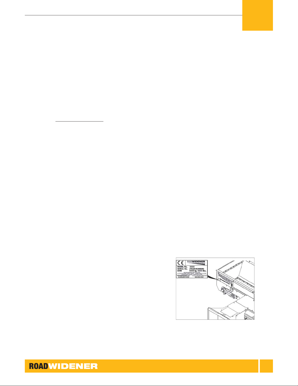
Model and Serial Tag
The model and serial number tag is located on the left side
of the hopper. Refer to this tag when needing any warranty
or service assistance. Also refer to this tag when ordering
any spare parts. This will help ensure that the correct part
is ordered.
1

OPERATOR, MAINTENANCE AND PARTS
6
6RGEKŞECVKQPU
Single Discharge Unit
Width of FH and FH-R Single Discharge Road Wideners 125 in. (3,175 mm)
Height of FH and FH-R Single Discharge Road Wideners 51 in. (1,300 mm)
Length of FH and FH-R Single Discharge Road Wideners 98 in. (2,489 mm)
Widths of Shoulders of Road Widening Material That Can Be Laid Down 12 in. (305 mm) to 48 in. (1,219 mm)
Number of Side Exit Chutes 1
Gross Weight of FH Single Discharge Road Wideners 2,900 lb (1,315 kg)
Height of Push Rollers 21 in. (530 mm)
Extra Amount Push Rollers Can Extend 12 in. (305 mm)
Conveyor Belt Type Rubber
Conveyor Belt Length and Width 8 ft (2.4 m) x 20 in. (508 mm)
Conveyor Speed Range 0-350 ft/min (1.8 m/sec)
Head and Tail Drum Diameter 10 in. (254 mm)
Typical Working Pressure 3,000 psi (207 bar)
Flow Rate 17.5 - 24.2 gal/min (79.6 - 111 l/min)
Hydraulic Fittings JIC and SAE
Maximum and Minimum Feed Rates 2.0 tons/hr (1.8 tonnes/hr)
Maximum Lump Size of Road Widening Material 10 in. (254 mm)
Optimum Traveling Speed Range While Laying Down Road Widening Material 0.5 to 1.5 mph (8.0 to 2.4 km/hr)
1
GENERAL INFORMATION

OPERATOR, MAINTENANCE AND PARTS
7
Dual Discharge Unit
Width of FH and FH-R Dual Discharge Road Wideners 138 in. (3,505 mm)
Height of FH and FH-R Dual Discharge Road Wideners 51 in. (1,300 mm)
Length of FH and FH-R Dual Discharge Road Wideners 98 in. (2,489 mm)
Widths of Shoulders of Road Widening Material That Can Be Laid Down 12 in. (305 mm) to 48 in. (1,219 mm)
Number of Side Exit Chutes 2
Gross Weight of FH Dual Discharge Road Wideners 3,400 lb (1,542 kg)
Height of Push Rollers 21 in. (530 mm)
Extra Amount Push Rollers Can Extend 12 in. (305 mm)
Conveyor Belt Type Rubber
Conveyor Belt Length and Width 9.5 ft (2.9 m) x 21 in. (533 mm)
Conveyor Speed Range 0-350 ft/min (1.8 m/sec)
Head and Tail Drum Diameter 10 in. (254 mm)
Typical Working Pressure 3,000 psi (207 bar)
Minimum Flow Rate 17.5 - 24.2 gal/min (79.6 - 111 l/min)
Hydraulic Fittings JIC and SAE
Maximum and Minimum Feed Rates 2.0 tons/hr (1.8 tonnes/hr)
Maximum Lump Size of Road Widening Material 10 in. (254 mm)
Optimum Traveling Speed Range While Laying Down Road Widening Material 0.5 to 1.5 mph (8.0 to 2.4 km/hr)
1
GENERAL INFORMATION

OPERATOR, MAINTENANCE AND PARTS
8
Crating and Uncrating
Instructions
Type FH Single Discharge & Dual Discharge and FH-R
Single Discharge & Dual Discharge Road Widener
machines are generally shipped on an open, atbed truck.
For exports, the machines are packaged in shipping crates
that are designed to ensure that the components will not
be damaged during transport. Use caution when unpacking
the shipping crates as the contents may have shifted during
transit.
Assembly
The Road Widener machines come fully assembled from
the factory; however, some accessories weigh more than
30 lb (15 kg). When lifting accessories or components
more than 30 lb (15 kg), Road Widener recommends that
a minimum of 2 people and appropriate lifting devices be
used to assemble accessories or components.
Optional accessories weighing more than 30 lb (15 kg) are:
• Shoe Extension Kit
• Pintle Push Plate
• Push Roller Extensions (the push roller extensions are
not more than 30 lb (15 kg), but to install the push roller
extensions, lifting more than 30 lb (15 kg) is required)
Optional Equipment
Some optional equipment can be ordered from Road
Widener for your specic job if needed.
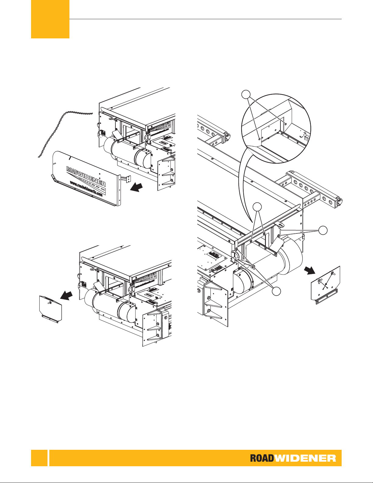
Roller Extension
If the rollers need to be extended closer to the dump
vehicle, roller extensions are available. The roller extensions
will extend the rollers an additional 12 in. (30 cm).
Figure 1: Roller Extension with Pins and Tubes Removed
1 ] Remove the pins holding the roller brackets to the
frame and remove the roller assembly.
2 ] Insert the roller extension tubes into the frame and pin
them in place.
3 ] Install the roller assembly into the extension tubes and
pin the roller assemblies in place.
1
GENERAL INFORMATION

OPERATOR, MAINTENANCE AND PARTS
9
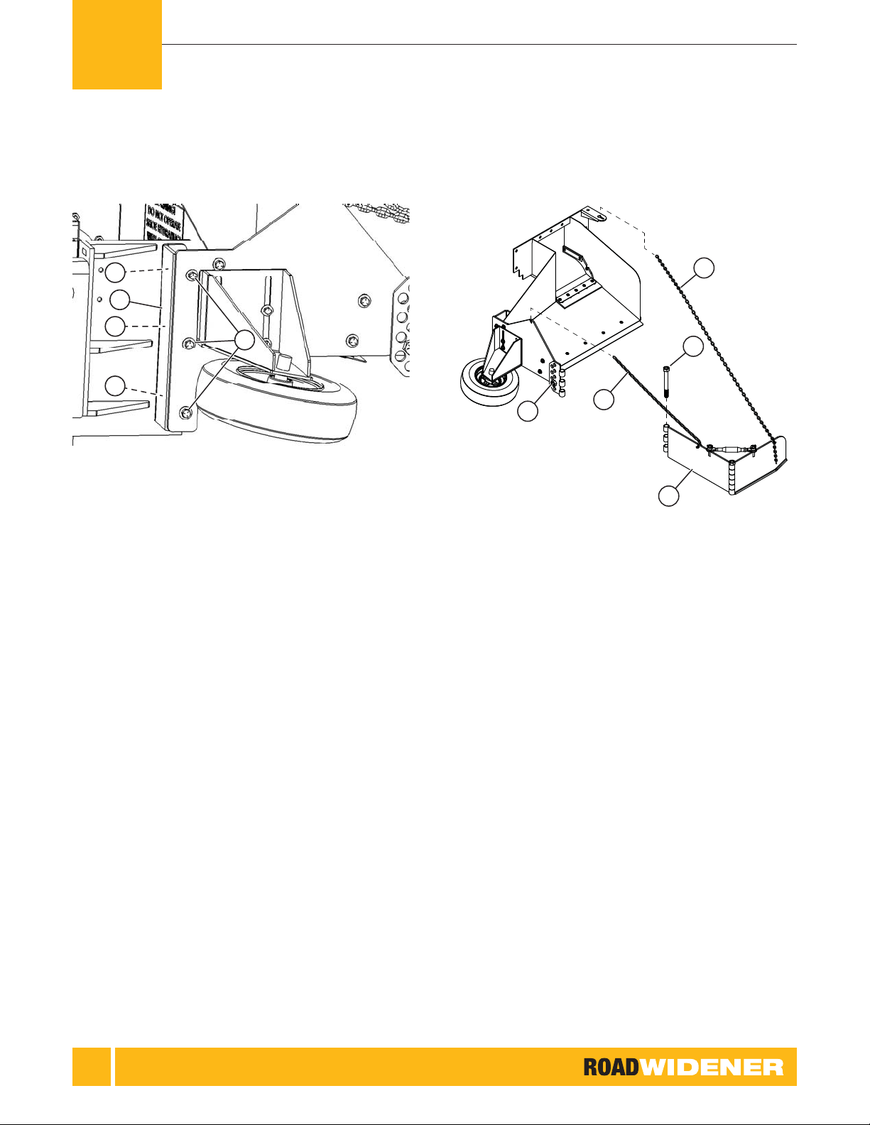
Curb Attachment
The curb attachment extends the hopper and allows the
shoe to be extended up over a curb to spread material
outside the curb. The roller wheel acts as a guide and
rides on the inside of the curb. It can be installed on a right
discharge, a left discharge or either side of a dual discharge
machine.
Figure 2: Curb Attachment Installed on Single Discharge Unit
INSTALLATION
OTE:NFor easier installation have the machine
mounted on a skid steer. An assistant may be
required for the removal and the installation
of some of the parts. This procedure shows
mounting the curb attachment onto a right
side single discharge machine. Mounting on
a left side discharge or a dual discharge is
similar.
1 ] Park the machine on a at, level surface.
3
4
2
1
Figure 3: Shoe Hardware Removal
1. Support Bracket Socket Head Screws
2. Shoe Mounting Bolts and Locknuts
3. Chain
4. Shoe
2 ] Remove the 2 bolts for the support bracket.
3 ] Remove the shoe mounting bolts and locknuts.
4 ] Unhook the chain and remove the shoe.
1
GENERAL INFORMATION
OPERATOR, MAINTENANCE AND PARTS
10
Figure 4: Shoe Removal
Figure 5: Discharge Plate Removal
5 ] On dual discharge units remove the closure plate if
required.
1
1
3
2
Figure 6: Chute Guide Plate
1. Socket Head Cap Screws
2. Outer Mounting Bolts
3. Inner Mounting Bolts
1
GENERAL INFORMATION

OPERATOR, MAINTENANCE AND PARTS
11
6 ] Remove the 4 socket head cap screws.
7 ] Remove the 2 outer mounting bolts.
8 ] Remove the 2 inner mounting bolts.
Figure 7: Chute Guide Plate Removal
9 ] Remove the chute guide plate.
Figure 8: Install Curb Attachment
10 ] Mount the curb attachment frame using the socket
head cap screws and the outer and inner mounting
bolts removed earlier.
1
GENERAL INFORMATION
OPERATOR, MAINTENANCE AND PARTS
12
3
2
2
2
1
Figure 9: Spacer Plate
1. Spacer Plate
2. Spacer Plate Inner Mounting Bolts
3. Spacer Plate Outer Mounting Bolts
11 ] Mount the spacer plate between the Road Widener
frame and the curb attachment using 6 bolts.
2
4
3
1
5
Figure 10: Installing Shoe and Chains
1. Shoe
2. Bolt
3. Rear Chain
4. Front Chain
5. Hinge
12 ] Install the shoe to the frame using the bolt. The shoe
hinge must pivot up and down.
13 ] Install the front and rear chains.
1
GENERAL INFORMATION
OPERATOR, MAINTENANCE AND PARTS
13
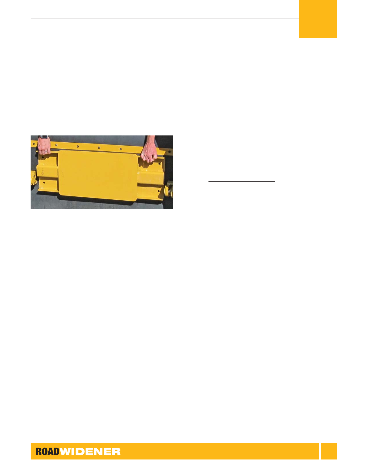
Push Plate
The push plate is used to push the dump vehicle when
not using the rollers. It usually pushes on the trailer hitch
receiver or the pintle hitch.
Figure 11: Push Plate with Four Pre-threaded Holes
1 ] Hold the push plate in place on the front of the
machine.
2 ] Attach the push plate to the frame at the four
pre-threaded holes using the approved hardware.
Pairing the Remote
Control
Your remote control comes factory paired. Almost never
will you need to pair your remote and receiver. The system
will behave like it is not paired if less than 12 volts DC and
10 amps are not present. If for some reason your remote
does not work, double-check the power supply(s). In the
unlikely event that pairing is required, see the separate
paring instructions that were supplied with the machine or
go to www.roadwidenerllc.com for the pairing procedure.
Remote systems require a 12-volt DC accessory socket
to be a 10-amp continuous solid-state connection. Using
lower than a 10-amp DC accessory socket will cause the
machine to not function. The handheld remote requires (2)
AAA batteries and the host machine must deliver 12 volts
DC and 10 amps. Connect your machine to a known
power source to verify! A direct circuit to the host machine’s
battery with a solid-state 10-amp fused circuit is advisable if
your remote does not function at initial start-up. USB ports
and some machine circuits provide less than 10 amps; if
your host machine falls into this category, adding a circuit
will be required.
1
GENERAL INFORMATION

OPERATOR, MAINTENANCE AND PARTS
14
Hardware Torque Chart
Use this chart when tightening hardware to the proper torque value.
U.S. Standard Cap Screw Torque Values
SAE
GRADE
NUMBER
GRADE 1 OR 2 GRADE 5 GRADE 8
SIZE/
THREADS
PER INCH
TORQUE in.-lb (N·m) TORQUE in.-lb (N·m) TORQUE in.-lb (N·m)
THREADS DRY OILED PLATED DRY OILED PLATED DRY OILED PLATED
1/4 – 20 62 (7) 53 (6) 44 (5) 97 (11) 80 (9) 73 (8) 142 (16) 133 (15) 124 (14)
1/4 – 28 71 (8) 62 (7) 53 (6) 124 (14) 106 (12) 97 (11) 168 (19) 159 (18) 133 (15)
5/16 – 18 133 (15) 124 (14) 106 (12) 203 (23) 177 (20) 168 (19) 292 (33) 265 (30) 230 (26)
5/16 – 24 159 (18) 142 (16) 124 (14) 230 (26) 203 (23) 177 (20) 327 (37) 292 (33) 265 (30)
3/8 – 16 212 (24) 195 (22) 168 (19) 372 (42) 336 (38) 301 (34) 531 (60) 478 (54) 416 (47)
ft-lb (N·m) ft-lb (N·m) ft-lb (N·m)
3/8 – 24 20 (27) 18 (24) 16 (22) 35 (47) 32 (43) 28 (38) 49 (66) 44 (60) 39 (53)
7/16 – 14 28 (38) 25 (34) 22 (30) 49 (56) 44 (60) 39 (53) 70 (95) 63 (85) 56 (76)
7/16 – 20 30 (41) 27 (37) 24 (33) 55 (75) 50 (68) 44 (60) 78 (106) 70 (95) 62 (84)
1/2 – 13 39 (53) 35 (47) 31 (42) 75 (102) 68 (92) 60 (81) 105 (142) 95 (129) 84 (114)
1/2 – 20 41 (56) 37 (50) 33 (45) 85 (115) 77 (104) 68 (92) 120 (163) 108 (146) 96 (130)
9/16 – 12 51 (69) 46 (62) 41 (56) 110 (149) 99 (134) 88 (119) 155 (210) 140 (190) 124 (168)
9/16 – 18 55 (75) 50 (68) 44 (60) 120 (163) 108 (146) 96 (130) 170 (230) 153 (207) 136 (184)
5/8 – 11 83 (113) 75 (102) 66 (89) 150 (203) 135 (183) 120 (163) 210 (285) 189 (256) 168 (228)
5/8 – 18 95 (129) 86 (117) 76 (103) 170 (230) 153 (207) 136 (184) 240 (325) 216 (293) 192 (260)
3/4 – 10 105 (142) 95 (130) 84 (114) 270 (366) 243 (329) 216 (293) 375 (508) 338 (458) 300 (407)
3/4 – 16 115 (156) 104 (141) 92 (125) 295 (400) 266 (361) 236 (320) 420 (569) 378 (513) 336 (456)
7/8 – 9 160 (217) 144 (195) 128 (174) 429 (582) 386 (523) 343 (465) 605 (820) 545 (739) 484 (656)
7/8 – 14 175 (237) 158 (214) 140 (190) 473 (461) 426 (578) 379 (514) 675 (915) 608 (824) 540 (732)
1.0 – 8 235 (319) 212 (287) 188 (255) 644 (873) 580 (786) 516 (700) 910
(1,234)
819
(1,110) 728 (987)
1.0 – 14 250 (339) 225 (305) 200 (271) 721 (978) 649 (880) 577 (782) 990
(1,342)
891
(1,208)
792
(1,074)
NOTE:
• Dry torque values are based on the use of clean, dry threads.
• Oiled torque values have been reduced by 10% when engine oil is used as a lubricant.
• Plated torque values have been reduced by 20% for new plated cap screws.
• Oiled torque values should be reduced by 10% from dry when nickel-based antiseize compound is used as a lubricant.
• Cap screws which are threaded into aluminum may require a torque reduction of 30% or more.
• The conversion factor from ft-lb to in.-lb is ft-lb x 12 equals in.-lb.
1
GENERAL INFORMATION

OPERATOR, MAINTENANCE AND PARTS
15
EC Declaration of
Conformity
Single and Dual Discharge Road Wideners
Models FH & FHR (Full Hydraulic & Full Hydraulic Remote)
1
GENERAL INFORMATION

16
!This safety alert symbol appears with most
safety statements. It means attention, become
alert, your safety is involved! Please read and
abide by the message that follows the safety alert symbol.
The words DANGER, WARNING, CAUTION and NOTICE
are used throughout this manual to highlight important
information.
Indicates a hazardous situation which, if not
avoided, will result in death or serious injury.
DANGER
!
Indicates a hazardous situation which, if not
avoided, could result in death or serious injury.
WARNING
!
Indicates a hazardous situation which, if not
avoided, could result in minor or moderate injury.
CAUTION
!
Indicates a situation which can cause damage to the Road
Widener, personal property, and/or the environment, or cause
the equipment to operate improperly.
NOTICE
OTE:NIndicates a procedure, practice or condition
that should be followed in order for the Road
Widener to function in the manner intended.
!WARNING
Before starting and operating the
Road Widener, be sure to read and
understand the content and safety
messages within this manual as well as
the safety labels on the Road Widener.
The operator is responsible for safe
operation of the Road Widener. Be sure
all potential users of the Road Widener
also understand these instructions.
Always keep your Road Widener in
proper working condition.
SAFETY2

OPERATOR, MAINTENANCE AND PARTS
17
It is the operator’s responsibility to read and
understand the skid steer or wheel loader safety
messages and proper operation and capabilities.
Only qualied and responsible operators should
be permitted to operate the machinery.
WARNING
!
Know the total rated operating capacity of
the skid steer or wheel loader which you will
be attaching to the Road Widener. The total
operating capacity should exceed the weight of
the Road Widener.
WARNING
!
!WARNING
Never operate the machine while under
the inuence of alcohol or drugs. Their
effect on vision and judgment make
operating the machine dangerous.
Road Widener machines should never be
operated with the casters off the ground.
Forward tipping may result. Road Widener
machines should be lifted off the casters while
loading and unloading only.
WARNING
!
Never operate the machine with the guards
missing or damaged. Tampering with or
modifying the guards may result in injury or
premature wear on the machine.
WARNING
!
!WARNING
Before operating the machine, read the
skid steer or wheel loader operation
manual and know what the acceptable
grade requirements are. The Road
Widener attachment will usually add
to the drive machine’s stability. Road
Widener assumes no responsibility of
tipping due to the angle of use.
Never allow an operator to sit or stand on Road
Widener attachment while in operation. A non-
slip surface is provided near the attachment plate
for entering and exiting skid steer only. Horizontal
surfaces may support maintenance personnel.
This should only occur with machinery stopped
and fully disconnected from power source.
WARNING
!
2
SAFETY

OPERATOR, MAINTENANCE AND PARTS
18
!WARNING
ALWAYS wear the appropriate personal
protective equipment as required by the
task at hand, including but not limited
to:
• Relatively tight and belted clothing
• Safety gloves
• Safety shoes/boots
• Safety eye glasses/goggles/shields
• Hearing protection, ear plugs
• Head protection, hard hats
Operating the machine requires the full
attention of the operator. Do not wear
radio or music headphones that may
interfere with jobsite communications
or monitoring the machine in operation.
!WARNING
Use extreme caution when near rotating
parts. Rotating parts can entangle
hands, feet, hair, clothing and/or
accessories. Traumatic amputation or
severe laceration can result.
• Keep hands and feet away from
rotating parts.
• Tie up long hair and remove jewelry.
• Operate equipment with all guards in
place.
• DO NOT wear loose-tting clothing,
dangling drawstrings or items that
could become caught.
Stay clear of all moving parts, rollers,
conveyor belt and skid steer when the
Road Widener is in operation.
Do not drive the Road Widener through gravel piles or asphalt
spills. Material can accumulate inside the belt and the belt
rollers causing premature belt wear or belt failure.
NOTICE
Always be environmentally responsible.
• Follow the guidelines of the EPA or other governmental
agencies for the proper disposal of hazardous materials.
Consult the local authorities or reclamation facility.
• NEVER dispose of hazardous materials irresponsibly
by dumping them into a sewer, on the ground, or into
groundwater or waterways.
• Failure to follow these procedures may seriously harm the
environment.
NOTICE
Inspect all hoses, ttings and hydraulic components on both
the Road Widener attachment and the drive machine before
operation of the hydraulic system. Repair any problems that
are discovered.
NOTICE
Do not lift with material in the hopper.
NOTICE
2
SAFETY
This manual suits for next models
1
Table of contents


